







7th August 2026
How to Control Runout in Long Shaft Machining: Setup, Grinding, and Inspection for Parts Up to 4 Meters
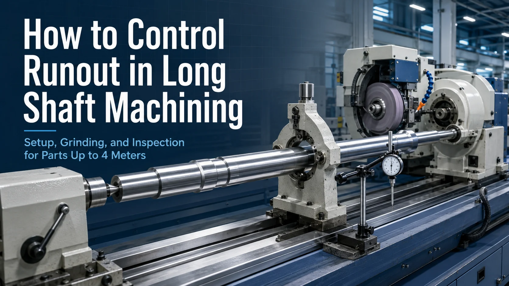
Long shaft machining becomes difficult when a part passes diameter inspection but still shows excessive runout, bow, taper, vibration, or assembly misalignment. The cause may begin in the raw material, appear during stock removal, develop after heat treatment, or result from an inspection setup that does not reproduce the drawing datum. For shafts approaching four meters, material condition, workholding, machining sequence, grinding, inspection, and packaging must form one controlled process.
Long Shaft Machining Runout: Diagnose the Pattern First
Runout is commonly checked by rotating the shaft through 360 degrees and comparing the indicator’s maximum and minimum readings at a specified position. The result is meaningful only when the datum, support method, gauge position, and permitted value are defined.
| Observed condition | Check first | Next action |
|---|---|---|
| Runout is concentrated near one end | Center holes, chucking, tailstock, datum transfer | Verify the setup axis |
| Maximum bow appears near the middle | Support spacing, stock straightness, cutting force | Review support and roughing |
| Diameter changes along the shaft | Tailstock alignment, tool wear, thermal drift | Separate geometric and thermal error |
| Runout increases after heat treatment | Residual stress, support, remaining allowance | Recheck straightness before finishing |
| Inspection reports disagree | Datum, support points, orientation, gauge position | Agree on one method |
This identifies whether the next review should focus on material, setup, grinding, or measurement.
Why Long Shafts Develop Runout, Taper, and Straightness Errors
Material Straightness, Residual Stress, and Heat-Treatment Distortion
A long bar may contain initial bow or uneven residual stress. Heavy material removal can release that stress and move a shaft that appeared straight during roughing. Thin sections, keyways, and large diameter changes increase the risk.
For parts requiring substantial stock removal or heat treatment, a staged route may be safer than machining directly to final size. Rough turning establishes the geometry, followed by a stability or heat-treatment step when specified, another straightness check, and finish machining. Remaining allowance should be distributed so final turning or grinding does not need to correct most of the error from one side.
The RFQ should identify material grade, supply condition, heat treatment, hardness, and incoming straightness requirements.
Cutting Force, Unsupported Length, Clamping, and Heat
A slender shaft deflects under radial cutting force. As unsupported length increases, the tool may push the workpiece away, causing taper, barrel shape, chatter, or inconsistent diameter. Excessive chuck, tailstock, or steady-rest pressure can also bend the shaft before cutting.
Lower cutting force, short tool overhang, staged passes, controlled support, and temperature management reduce risk. A strategy that works on a rigid section may fail at the smallest diameter. Buyers should ask how the supplier will support that section, manage tool wear and thermal growth, and perform in-process checks.
Choosing the Right Setup for Long Shaft Turning
The setup should reflect shaft length, diameter, weight, material, critical datums, and permitted runout. Buyers can review CK Metal Tech’s long shaft CNC machining and grinding capabilities before submitting a drawing.
Between-Centers Turning and Tailstock Alignment
Turning between centers can preserve one rotational axis through several operations when center holes remain available as process datums. It is useful when multiple journals must relate to the same axis, although end geometry, weight, or feature access may require another setup.
Center holes must be prepared and protected because inconsistent seating transfers into runout. Tailstock alignment and thrust also matter: insufficient support permits movement, while excessive force may bow a slender shaft. The supplier should check initial indicator readings, explain how the part will be reloaded, and confirm whether center holes are temporary process features or drawing-controlled features.
Steady Rest vs. Follow Rest
A steady rest supports the shaft at a fixed position; a follow rest moves with the cutting tool. The correct choice depends on where the unsupported span develops.
Official machine guidance describes steady rests as support for long or narrow shafts and instructs operators to adjust rollers without causing workpiece deflection. It also recommends rotating the part and checking it with an indicator after adjustment.
Rollers that are too loose provide little control; rollers that are too tight can create friction, marks, heat, or artificial bending. The supplier should identify support locations and explain how alignment will be rechecked after repositioning.
Machining Sequence for Controlling Long-Shaft Runout
Rough Turning, Stability Review, and Finish Turning
A sound process separates heavy stock removal from final geometry control. Rough turning establishes the shape and reveals how the blank responds as material is removed. The shaft can then be checked for bow and datum movement before heat treatment, semi-finishing, or grinding.
A typical route is:
Material review → datum preparation → rough turning → stability or heat-treatment step → straightness review → semi-finishing → finish turning or grinding → final inspection.
The exact route depends on material, geometry, hardness, and drawing requirements. Repeated chucking should be minimized or controlled through consistent center holes, journals, or other process datums.
When Grinding Is Required—and When Turning Is Enough
Grinding may suit hardened journals, bearing fits, wear surfaces, or requirements involving surface condition, roundness, cylindricity, and relationships between diameters. It should not be added automatically. If finish turning meets the drawing, another setup may add cost and datum-transfer risk.
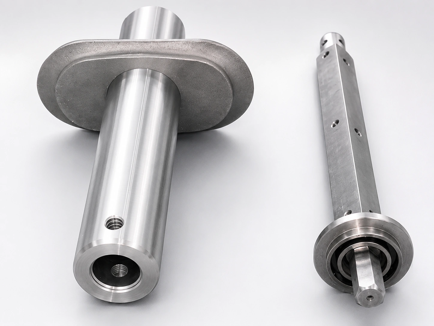
For ground shafts, confirm the grinding datum, support method, allowance, heat-treatment sequence, and equipment range. CK Metal Tech’s precision-turned shaft components with grinding use a published route combining precision turning, grinding, and quenching for custom alloy-steel or stainless-steel designs.
This product does not establish a four-meter grinding range. Maximum length, diameter, weight, and geometry must be verified for each drawing.
How to Inspect Runout and Straightness on a Long Shaft
Define the Datum Axis Before Selecting the Gauge
Circular runout, total runout, straightness, roundness, and coaxial relationships describe different conditions. A shaft may meet diameter tolerance while failing rotational function. The drawing should identify the functional datum axis and the characteristic that affects assembly.
The datum may come from center holes, two bearing journals, or another functional feature. Measuring one section does not prove the complete shaft meets total runout or straightness requirements. Reports should state the datum, support method, gauge positions, orientation, rotation method, and result.
Control Gravity Sag and Measurement Support
A long slender shaft can sag under its own weight during horizontal inspection. Between-centers measurement, rollers, V-blocks, and coordinate measurement systems may produce different readings if support positions and datums are not correlated.
Inspection equipment must match the workpiece envelope, weight, access, and required uncertainty. A CMM may suit some features, but it should not be assumed that every machine can accommodate a complete four-meter shaft. Supplier and buyer should agree on support spacing, orientation, rotation method, and measurement correlation.
CK Metal Tech has CMM, 2.5D measurement, metallographic, and hardness-testing resources, but the method for a full-length four-meter shaft must be confirmed against the equipment range.
Troubleshooting Long-Shaft Machining Defects
Runout near one end points first to the chuck, center hole, tailstock, or datum transfer. Maximum bow near the middle suggests stock straightness, support spacing, cutting force, or stress release. Gradual taper calls for checks of alignment, tool wear, machine geometry, and temperature. Periodic chatter may indicate poor rigidity, unsuitable speed, excessive tool overhang, or unstable rest contact.
If runout increases after heat treatment, verify straightness before removing final allowance. If grinding introduces new error, review grinding heat, support pressure, wheel condition, and datum correlation. Rework should not begin until the cause and remaining allowance are understood.
RFQ Checklist for Long Shafts Up to 4 Meters
Drawing, Material, and Application Data
Provide the current 2D drawing and 3D model, total and effective machining lengths, maximum and minimum diameters, estimated weight, material grade and condition, center holes, functional datums, and all stepped, threaded, tapered, keyed, or drilled features.
State circular runout, total runout, straightness, surface requirements, heat treatment, hardness, grinding scope, and inspection records. Application details such as speed, load, mating components, and environment help identify critical features. Include quantities and any photographs or reports from an existing defect.
Capacity, Inspection, and Packaging Questions
Ask the supplier to confirm usable between-centers length, maximum diameter and weight, lifting method, tailstock and rest configuration, and which turning, heat treatment, grinding, and inspection stages are internal or outsourced. Confirm grinding range rather than assuming it matches turning capacity.
The quotation should identify datum simulation, inspection supports, sample and production setups, and packaging. A shaft that passes inspection can still bend if supported incorrectly during storage or transport.
How to Choose a Long Shaft Machining Supplier
Evaluate the Complete Manufacturing Route
A suitable supplier should explain how material review, datum preparation, roughing, support, heat treatment, finishing, grinding, inspection, and packaging connect. The review should identify where straightness is checked, how setups are repeated, which features establish the final axis, and what happens if the shaft moves after heat treatment.
Buyers should confirm whether first articles and production parts use the same route, which records are available, and how abnormal results are handled. Confirming machine length without discussing weight, support, grinding, and inspection is not a complete feasibility review.
Relevant CK Metal Tech Capabilities
Zhejiang Chuangkai Mechanical and Electrical Technology Co., Ltd. connects machining with related processes through its integrated precision metal manufacturing capabilities. Buyers can also review about Zhejiang Chuangkai Mechanical and Electrical Technology Co., Ltd. when evaluating the supplier.
Confirmed resources include 18 precision CNC lathes, turning capacity for workpieces up to approximately four meters, internal and external cylindrical grinding, centerless grinding, thread rolling, tapping, and drilling. CK Metal Tech also holds IATF 16949 certification, while its website presents machining, stamping, sheet-metal fabrication, surface treatment, and assembly as connected services.
Maximum diameter, weight, grinding length, support arrangement, and achievable runout or straightness must still be verified for each project.
Conclusion
Controlling runout in long shaft machining requires more than a long-bed lathe. Material condition, datums, support pressure, cutting force, heat treatment, grinding, inspection, and transport must form one traceable route. The objective is to meet the drawing under an agreed measurement method, not to promise “zero runout.”
For a process review, submit the drawing, material, length, diameters, estimated weight, runout and straightness requirements, heat treatment, grinding scope, quantity, application, and any defect photographs or reports. Buyers can request a long shaft machining review from CK Metal Tech.
Frequently Asked Questions
How can runout be reduced when machining a long shaft?
Check raw-material straightness, datums, chuck and tailstock alignment, support location, cutting force, tool condition, and temperature. Separate roughing from finishing when stress release is likely, then inspect with the agreed datum and support method.
When is a steady rest required for long shaft turning?
A steady rest may be needed when the unsupported span permits deflection, vibration, or unstable size. The decision depends on diameter, length, weight, material, cutting force, geometry, and tolerance.
Should a long shaft be ground after CNC turning?
Grinding is appropriate when hardness, bearing fits, wear surfaces, roundness, cylindricity, or surface requirements cannot be met reliably by turning. It may be unnecessary when finish turning satisfies the drawing.
How is total runout measured on a four-meter shaft?
Define the datum axis, support arrangement, rotation method, and measurement locations. The method must consider gravity sag, equipment range, and correlation between supplier and customer inspection.
What information is needed for a long shaft machining quote?
Provide drawings, material condition, length, diameters, weight, datums, runout and straightness tolerances, surface requirements, heat treatment, grinding, features, quantities, application, inspection records, and packaging expectations.

Leave a reply