CHUANGKAI

A ich l A N D

Laden


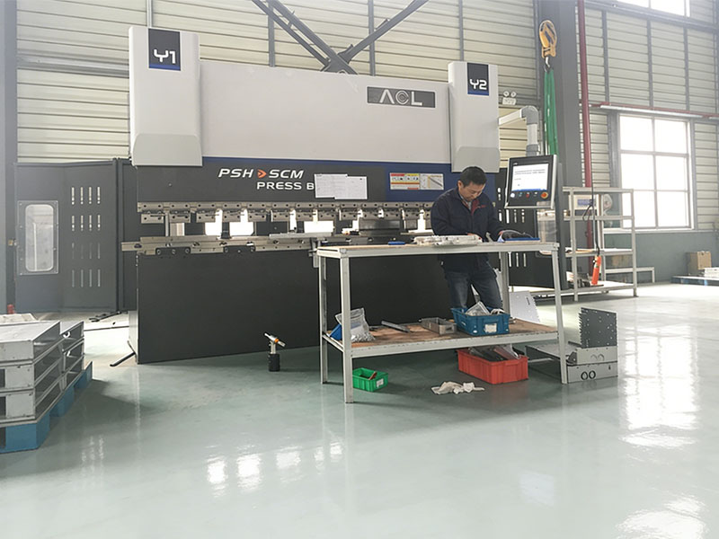
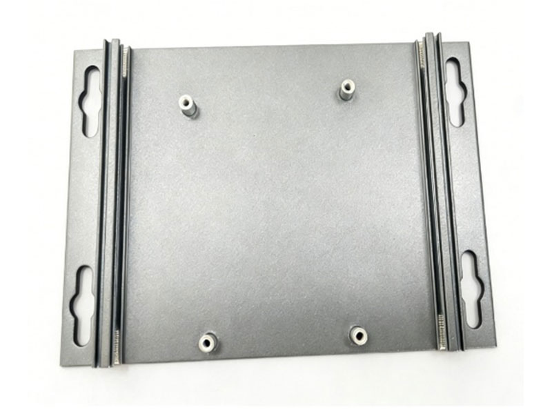
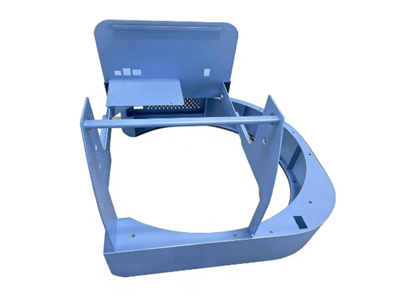
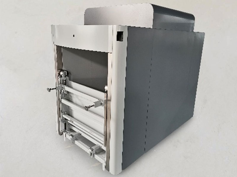
CNC-Biegen

Menge: 5

Genauigkeit: ±0,1 mm

Maximale Tragfähigkeit: 150 Tonnen

Wiederholgenauigkeit der Positioniergenauigkeit: ±0,02 mm

Vorteile: Komplexe Mehrfachbiegevorgänge, hohe Konsistenz

- unser Service

OEM/ODM

78C15086-3AEC-4764-B985-CBB656BC0C94
                                   

Konstruktion und Fertigung von Präzisionsstanzwerkzeugen

Die wichtigsten Stanzmaschinen der Stanzwerkstatt sind: 13 Hochgeschwindigkeits-Präzisionsstanzpressen mit Schließkräften von 16, 25, 40, 60, 80, 110 und 200 Tonnen. Die Stanzgeschwindigkeit der Präzisions-Hochgeschwindigkeitsstanzpressen beträgt bis zu 500 Hübe pro Minute.
Werkstoffe für die Stanzverarbeitung: Messing, Phosphorbronze, Berylliumbronze, Nickel-Weißkupfer sowie verschiedene Stahlsorten und Edelstahlmaterialien, Ni-Bänder, kaltgewalzter Stahl, Bandstahl (einschließlich vorplattierter), verzinkte Bleche, kohlenstoffarmer Stahl, Federstahl und andere Verbundwerkstoffe.

78C15086-3AEC-4764-B985-CBB656BC0C94
                                   

Präzisionsblechfertigung

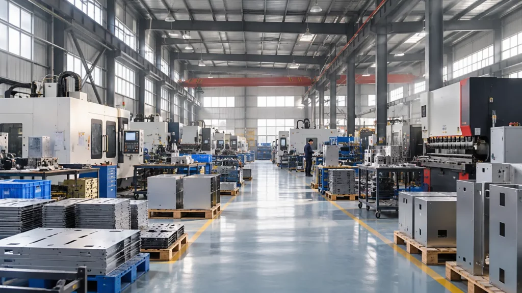
Die Blechwerkstatt ist mit Präzisions-Blechbearbeitungsmaschinen ausgestattet, darunter 2 große, hochmoderne CNC-Laserschneidmaschinen, 1 CNC-Stanzpresse, 5 CNC-Biegemaschinen sowie Nietmaschinen, Schweißmaschinen, Schleifmaschinen, Drahtziehmaschinen und andere Geräte.
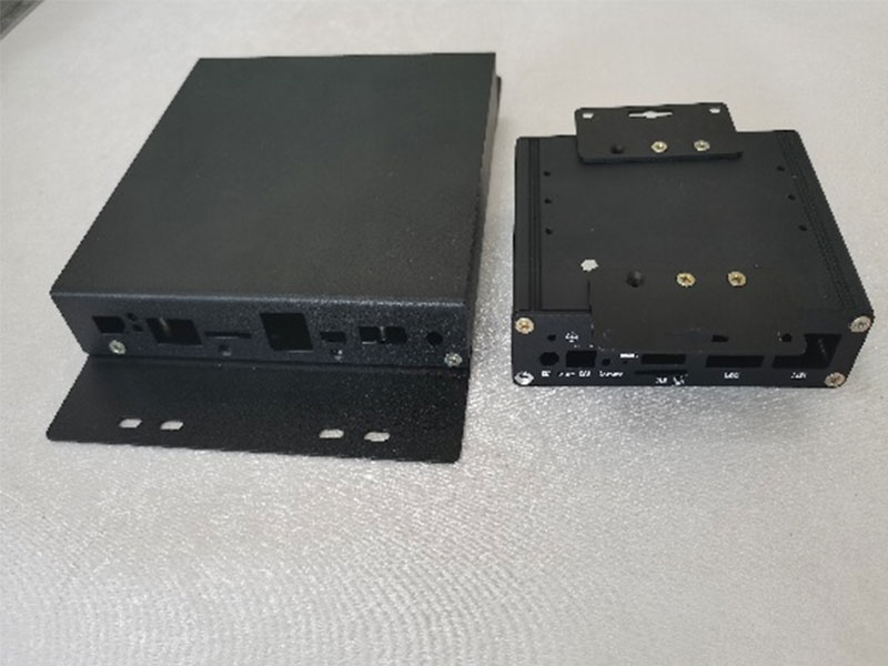
Die verarbeiteten Produkte decken Bereiche wie Industrieautomation, Medizintechnik, Elektrotechnik, Verteilerkästen und weitere Anwendungsgebiete ab. Die Anlage ermöglicht Präzisionsbearbeitungen wie Schnellschneiden und Blechbearbeitung an folgenden Metallwerkstoffen: Edelstahl, Kohlenstoffstahl, Siliziumstahl, Aluminiumlegierungen, verzinktes Blech, aluminiumverzinktes Blech usw.

78C15086-3AEC-4764-B985-CBB656BC0C94
                                   

Pulverbeschichtung & Lackierung

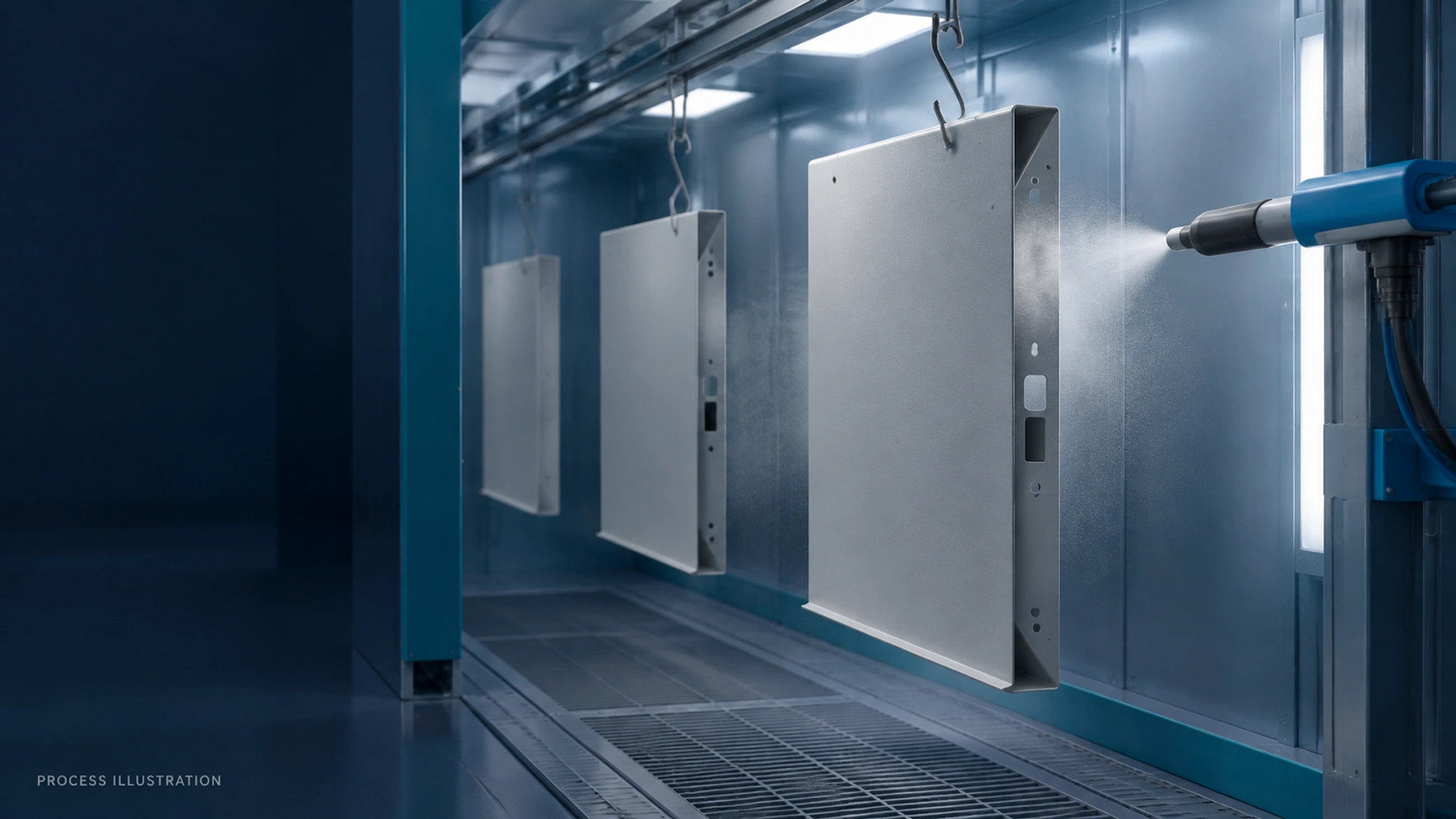
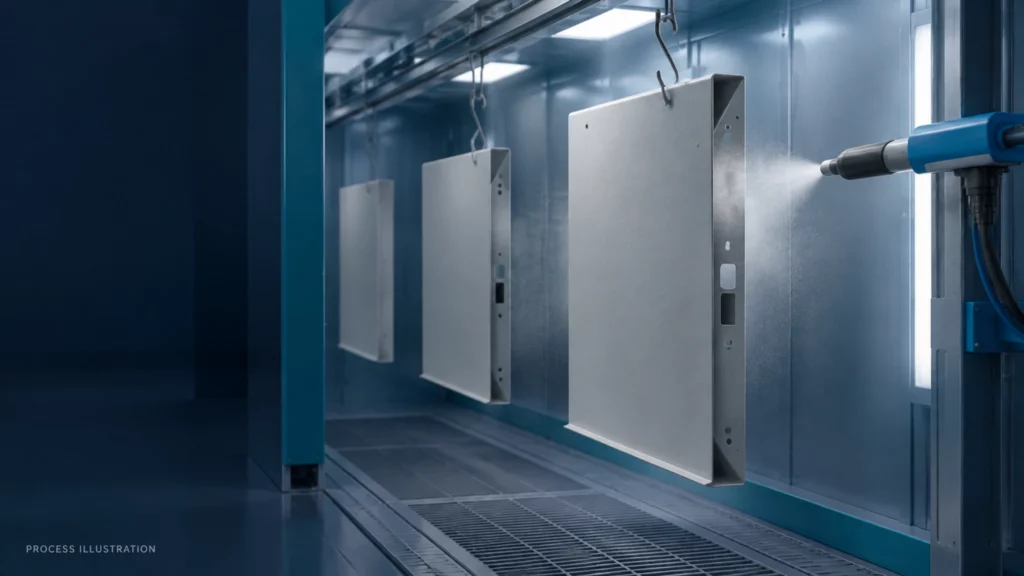
Eine automatische Pulverbeschichtungsanlage;
Eine manuelle Pulverbeschichtungsanlage (für große Teile und große Kartons);
Eine manuelle Lackierlinie (für große Teile und große Kartons);
Eine automatische Hybrid-Anlage zum Pulverbeschichten und Lackieren befindet sich im Bau.

78C15086-3AEC-4764-B985-CBB656BC0C94
                                   

Präzisionsbearbeitung

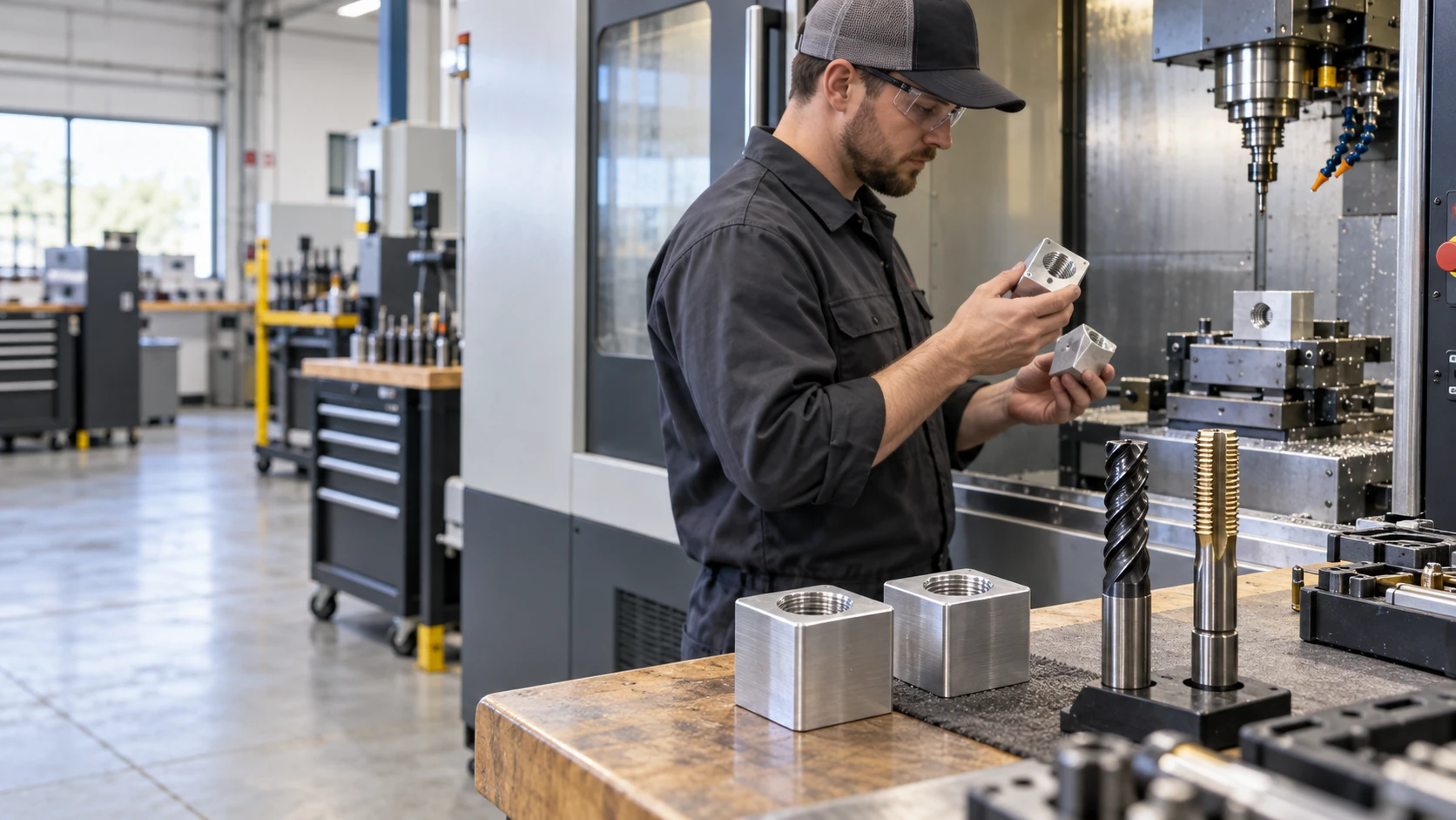
Die Bearbeitungswerkstatt ist mit Präzisionsmaschinen ausgestattet, darunter 6 Sätze 4-Achs-CNC-Maschinen, 1 Satz 5-Achs-Langdrehmaschine, 13 Sätze Präzisions-CNC-Drehmaschinen, 4 Sätze CNC-Fräsmaschinen, 16 Sätze Taiwan Mingyang Präzisions-Automatendrehmaschinen sowie Präzisions-Standarddrehmaschinen, Präzisions-3-Achs-Digital-Display-Fräsmaschinen, Präzisions-Tischdrehmaschinen, Taiwan Jizuan automatische Kantenfräsmaschinen, Präzisions-Gewinderollmaschinen, Gewinderollwerkzeuge, Präzisions-Gewindeschneidmaschinen, Präzisions-Digital-Display-Fräsmaschinen aus Taiwan, Präzisions-Messerschleifmaschinen, Innen- und Außenrundschleifmaschinen, spitzenlose Schleifmaschinen, Sägemaschinen, Ultraschallreinigungs- und Trocknungsanlagen, Poliermaschinen, Elektroschweißgeräte, Lichtbogenschweißgeräte und andere Ausrüstung.

jüngste
Blogartikel

Powder Coating Defects on Sheet Metal How to Prevent Edge Rust and Thread Build-Up

04
September


Powder Coating Defects on Sheet Metal How to Prevent Edge Rust and Thread Build-Up

Powder coating defects on sheet metal are often most costly when they affect function rather than appearance. A panel may look acceptable across its flat surfaces while rust begins at exposed edges, or a threaded hole that passed inspection before finishing may no longer accept its fastener after coating. These failures have different immediate causes, but both point to the same purchasing lesson: edge condition, surface preparation, masking, coating requirements, assembly interfaces, and inspection should be defined before the parts enter production.

Why Do Powder-Coated Sheet Metal Edges Rust First?

Sharp Edges Can Receive Less Effective Coating Coverage

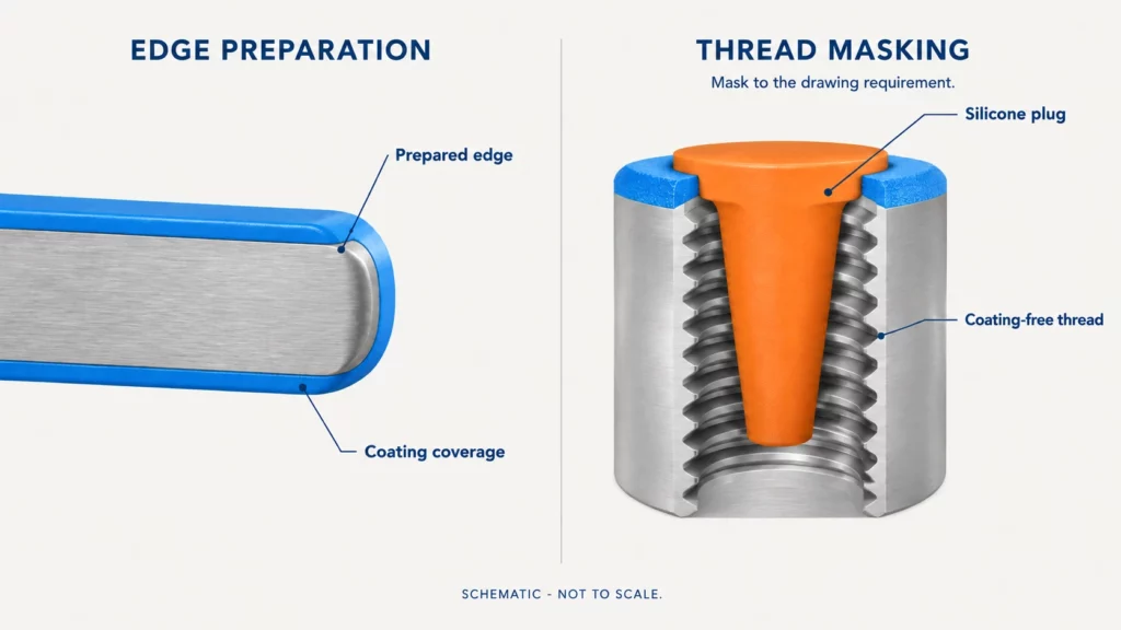
A sharp edge is not the same coating surface as a broad flat panel. The Powder Coating Institute defines edge coverage as a powder coating’s ability to flow over, build on, and adhere to sharp corners, angles, and edges. Coating behavior at those locations therefore deserves separate attention during design and inspection.

This helps explain a common failure pattern: the main panel remains coated while rust appears first along a cut or sharply formed edge. Technical guidance from a major powder-coating manufacturer also notes that sharp edges can retain less coating than the surrounding surface, reducing corrosion protection at those locations.

When only the edges are failing, engineers should inspect the edge geometry, burr condition, surface preparation, local film condition, and any damage after coating. Laser-cut, punched, sheared, or ground edges should not automatically receive identical preparation because their actual condition may vary.

The next action is not simply to specify “more powder.” Determine whether the weak point is created by fabrication, preparation, the coating system, or post-coating damage.

Rule Out Pretreatment, Contamination, and Handling Damage

Edge rust should not automatically be blamed on edge coverage. If corrosion also appears on broad surfaces, around welds, or beneath apparently intact coating, the investigation should widen.

Oil, oxidation, welding residue, burrs, and uneven surface conditions can affect the final finish. CK Metal Tech’s existing powder coating for sheet metal parts guide places cleaning and surface conditioning before coating and specifically identifies contamination, rust, weld residue, and sharp burrs as issues that should be reviewed.

Timing also matters. If parts leave production in acceptable condition but develop damage after packing, transport, installation, or assembly, examine impact and abrasion at edges and corners. Coating that has been mechanically damaged exposes a different root cause from an edge that never received sufficient protection. For larger housings and frames, powder coating handling and batch production should therefore be considered as part of the defect investigation rather than treating the coating booth as the only possible source.

How to Prevent Edge Rust Before Powder Coating

Treat Edge Condition as a Sheet Metal DFM Requirement

Edge-rust prevention starts during sheet metal fabrication. A drawing may carefully specify hole position, bend angle, and overall dimensions while saying nothing about an environmentally exposed cut edge.

For exposed covers, cabinets, frames, or brackets, determine which edges are functionally or environmentally critical. These may justify specific deburring, edge finishing, or other preparation requirements before coating. Internal edges that are inaccessible and noncritical should not automatically receive the same processing; unnecessary finishing adds manufacturing cost without necessarily improving function.

A practical DFM review should ask:

  • Will this edge be exposed to moisture, handling, or frequent contact?
  • Does the fabrication method leave a burr or unusually sharp transition?
  • Is the edge visible after assembly?
  • Does the corrosion requirement apply equally to edges and large surfaces?
  • Is the requirement clearly shown on the latest drawing?

The objective is not to apply one universal edge radius. The appropriate edge condition depends on material, geometry, fabrication process, coating system, operating environment, and customer specification.

Match Corrosion Protection to the Operating Environment

A powder-coated indoor cabinet and an outdoor equipment housing should not be specified from the same assumptions. Humidity, chemicals, cleaning, condensation, physical handling, substrate material, and expected service environment all influence the corrosion strategy.

Where corrosion exposure is more demanding, the coating supplier may need to evaluate pretreatment, primer, coating chemistry, or a system designed for stronger edge performance. Some commercial corrosion-protection powder systems are specifically designed around improved edge coverage, illustrating why the coating system has to be selected against the application rather than only by color and texture.

If a project requires a corrosion test, define the applicable method and acceptance requirement in the specification or RFQ. Do not assume that one salt-spray duration, primer system, or coating thickness applies to every powder-coated sheet metal part.

Why Does Powder Coating Build Up in Threaded Holes?

Coating Build-Up Can Turn a Good Thread Into an Assembly Failure

Powder coating on threads creates a different problem from edge rust. A coating layer that is harmless on a large panel can interfere with thread engagement, a precision hole, an electrical contact surface, or another fit-sensitive feature.

This is why a tapped hole can meet its machining requirement before coating but cause difficulty when a screw is installed afterward. CK Metal Tech’s published coating guidance specifically identifies threaded holes, grounding points, bearing surfaces, PEM fasteners, assembly contact surfaces, and tolerance-sensitive slots as areas requiring review before coating.

When a bolt does not start after powder coating, first establish whether the thread was acceptable before finishing. Then inspect where coating accumulated and whether the drawing identified the thread as a no-coat feature.

Repeatedly scraping or chasing threads after coating may correct individual parts, but it also creates rework and can damage the coating boundary. In repeat production, prevention is generally easier to control than relying on manual cleanup after curing.

Decide Which Threads and Functional Surfaces Must Remain Coating-Free

Not every hole or threaded feature has the same function. An internal tapped hole, external threaded stud, grounding connection, bearing surface, mating flange, and ordinary clearance hole should be reviewed separately.

Industrial masking guidance identifies threads, studs, ports, sealing surfaces, grounding points, and other fit-critical areas as typical locations that may need protection from coating.

Before releasing the drawing, ask:

  • Does coating interfere with fastener engagement?
  • Must the surface provide electrical continuity?
  • Is the area part of a precision fit or mating interface?
  • Does the coating boundary affect sealing or assembly?
  • Does the supplier know exactly how much of the feature must remain bare?

A vague instruction such as “mask threads” may still create disagreement if the required masking depth, surrounding bare area, or boundary is unclear.

How to Mask Threads and Functional Surfaces Before Powder Coating

Match Plugs, Caps, and Tape to the Feature Geometry

The masking method should follow the geometry and function of the no-coat area rather than using one method for every feature.

Feature Main risk Masking approach to evaluate Buyer should confirm
Internal tapped hole Coating inside thread Plug Diameter, depth, lead-in
External threaded stud Coated external thread Cap Required mask length
Grounding hole Loss of conductive contact Plug/cap with surrounding mask Required bare contact area
Flat mating surface Assembly interference Tape or disc Boundary and functional tolerance

Industrial masking suppliers commonly separate plugs for holes, ports, bores, and internal threads from caps used on studs and external projections, while tapes and discs are used to define flat no-coat areas.

Blind holes, through holes, countersunk features, irregular contours, and high-volume recurring parts may require different solutions. Buyers should therefore specify the functional no-coat requirement and let the masking method be reviewed against the actual geometry and production process.

Plan PEM Hardware and Secondary Thread Work Before Coating

PEM hardware, threaded inserts, studs, and secondary tapping should be considered as part of the manufacturing sequence rather than added as an afterthought.

Installing hardware before coating may create masking requirements around the fastener and adjacent contact area. Installing it afterward may change handling or assembly requirements. Post-coat thread chasing may remove unwanted coating but can also add labor and disturb the finished boundary.

The appropriate sequence depends on part design, hardware type, coating specification, assembly method, and production quantity. Before sampling, fabrication, finishing, and assembly requirements should be reviewed together so the RFQ clearly identifies which features are installed, machined, masked, or inspected at each stage.

How to Inspect Powder-Coated Parts Before Batch Production

Inspect Edge Condition, Thread Function, and Assembly Fit Together

Visual appearance alone does not prove that a coated part is ready for production. Inspection should follow the reasons the coating is specified.

Check exposed edges for coating continuity and damage. Verify critical threaded features using the inspection method defined for the project. Confirm masked areas and coating boundaries. Where fit matters, assemble the actual mating fastener or component rather than relying only on the uncoated dimensional report.

First-article review is particularly useful when a new drawing combines tight interfaces, masked features, cosmetic requirements, and corrosion exposure. Batch inspection should then retain the checks that protect those critical functions.

Handling remains part of this review. A finished enclosure can pass dimensional and cosmetic inspection and still be damaged during packing or transfer. CK’s published finishing guidance treats packaging and edge protection as part of the overall coating workflow rather than a separate purchasing issue.

Define Corrosion Validation From the Project Requirement

Corrosion validation should follow the intended application and customer specification. A project exposed to outdoor moisture may require a different validation plan from an indoor machine cover.

Specify the test method, specimen condition, coating system, acceptance criteria, and relevant surfaces when formal corrosion verification is required. The Powder Coating Institute distinguishes corrosion, edge coverage, pretreatment, and creepage as separate technical concepts, reinforcing the need to define what the project is actually evaluating.

Avoid copying a test duration or acceptance limit from an unrelated product. The correct requirement may vary with substrate, pretreatment, coating system, environment, geometry, and customer standard.


Powder coating defect prevention matrix for sheet metal showing edge rust, thread build-up, masking, inspection, and RFQ requirements

What Should OEM Buyers Put in a Powder Coating RFQ?

A useful RFQ should make functional coating requirements visible before the supplier prices the work. Include the base material, drawing revision, application environment, exposed critical edges, threaded holes and studs, PEM hardware, grounding points, mating surfaces, no-coat zones, cosmetic surfaces, corrosion expectations, coating specification if defined, inspection requirements, quantity, and packaging needs.

CK’s existing guidance similarly recommends defining material, masked areas, corrosion expectations, cosmetic surfaces, coating requirements, and packaging before production.

When problems have already occurred, send defect photographs, the affected drawing revision, mating hardware if relevant, and information on when the rust or assembly problem appeared. That gives the supplier a better basis for root-cause review than a request to “improve coating quality.”

Wie man einen Lieferanten für Blechbearbeitung und Pulverbeschichtung auswählt

Look Beyond the Powder Coating Booth

Edge rust and thread build-up illustrate why finishing quality cannot be separated completely from fabrication quality. The edge may originate in laser cutting, punching, bending, grinding, or welding; the blocked thread may originate in an incomplete drawing or masking plan.

A supplier should therefore be able to review the connected route from fabrication through finishing, inspection, assembly fit, and packaging. CK Metal Tech publicly lists sheet metal cutting, punching, bending, riveting and welding alongside powder coating and painting capabilities. Buyers considering sheet metal fabrication and powder coating should ask how critical edges, threads, no-coat areas, and finished assemblies will be controlled—not simply whether a powder coating line is available.

CK Metal Tech also describes powder coating as part of its broader integrierte Präzisionsmetallfertigungskapazitäten, allowing fabrication and surface-finish requirements to be reviewed within the same manufacturing scope. The project drawing and acceptance criteria should still determine whether that capability matches the application.

Abschluss

Edge rust and thread build-up require different immediate corrections, but both are easier to prevent when fabrication, preparation, masking, coating, inspection, and assembly are treated as one manufacturing plan. Define critical edges and no-coat features on the drawing, match corrosion requirements to the operating environment, and validate coated parts in their final functional condition.

For a defect or new-project review, prepare the drawing, material, application environment, affected dimensions or threads, coating requirement, target quantity, mating hardware, and any defect photographs or samples. Buyers can Kontaktieren Sie CK Metal Tech with these details for a manufacturability and finishing review.

FAQs About Powder Coating Edge Rust and Thread Build-Up

Why does powder coating rust first on sharp edges?

Sharp edges can receive different coating buildup from broad flat surfaces, making edge coverage an important corrosion consideration. Inspect the edge condition, preparation, local coating, environment, and possible handling damage before assigning the root cause.

Should threaded holes be masked before powder coating?

Fit-critical threaded holes should be reviewed as potential no-coat areas. Plugs are commonly used to protect holes and internal threads, but the correct masking requirement depends on thread function, geometry, coating specification, and assembly needs.

Can threads be tapped again after powder coating?

Threads can be reworked in some manufacturing routes, but post-coat tapping or thread chasing adds another operation and can disturb coating at the boundary. For repeat production, determine whether masking or a planned secondary operation provides the more controlled process.

How do I keep powder coating off grounding and mating surfaces?

Identify the required bare area on the drawing and choose masking according to geometry. Plugs or caps can protect holes and studs, while tapes or discs can define flat no-coat zones; specialized masking can also create an uncoated area around grounding features.

CNC Machining RFQ Checklist What to Send for an Accurate Production Quote

03
September


CNC Machining RFQ Checklist What to Send for an Accurate Production Quote

A CNC machining RFQ can produce very different prices when suppliers are working from different drawing revisions, material assumptions, tolerances, quantities, finishes, or inspection scopes. For a production quote, the goal is not simply to receive a price. It is to give each supplier enough controlled information to quote the same finished part under the same assumptions. A complete CNC machining RFQ checklist therefore needs to cover files, technical requirements, production demand, secondary operations, quality requirements, and quotation exclusions.

What Does a CNC Machining Supplier Need for an Accurate Quote?

Separate the Minimum RFQ Package From Project-Specific Requirements

A useful CNC machining quote package should first identify the part, current revision, geometry, material, quantity, critical tolerances, and required finished condition. If any of these are unknown, state that clearly instead of allowing each supplier to make a different assumption.

A practical minimum package usually includes:

  • Current part number and revision
  • 3D CAD model
  • Controlled 2D drawing when required
  • Material specification
  • Quote quantity
  • Critical dimensions and tolerances
  • Threads and functional features
  • Heat treatment or surface finish, if applicable

Production projects may also require annual demand, inspection documentation, packaging, mating-component information, marking, or special handling. The requirement depends on the application rather than a universal checklist.

What CAD Files and Drawings Should You Send for a CNC Machining Quote?

When Is a STEP File Enough—and When Do You Need a 2D Drawing?

A STEP model is useful for communicating part geometry. STEP is part of the ISO 10303 family for exchanging product data between computer systems. However, geometry alone may not communicate all manufacturing requirements.

A simple prototype with noncritical dimensions may sometimes be evaluated mainly from the 3D model. A production component with GD&T, special threads, surface roughness requirements, controlled datums, heat treatment, or inspection notes generally needs additional product-definition information.

ASME Y14.5 describes GD&T as a standardized language for communicating design requirements on engineering drawings, digital models, and related documents. The purchasing question is therefore not “Is STEP enough?” in isolation, but “Does the RFQ clearly communicate everything that controls form, fit, function, and inspection?”

Keep Part Numbers, File Names, and Revisions Consistent

Revision mismatch is one of the easiest ways to make CNC quotations incomparable. If one supplier quotes Rev B while another receives Rev C, differences in geometry, tolerance, or finishing can appear as price differences.

Use the same part number, model revision, drawing revision, quantity, and specification package for every bidder. When engineering changes occur, identify which files have been superseded and request confirmation that the revised quotation is based on the latest package.

For repeat production, this discipline becomes even more important because the quoted process, inspection plan, fixture assumptions, and secondary operations may all depend on the released revision.

How Should You Specify Material and Production Quantity?

Specify the Exact Material Requirement—and Whether Alternatives Are Allowed

“Aluminum” or “stainless steel” may be insufficient for an accurate production quote. When the application requires a particular grade, condition, temper, hardness, or material specification, put it on the drawing or RFQ.

If alternatives are acceptable, state that explicitly. A supplier should not have to decide independently whether a different alloy or stock condition is functionally equivalent.

Also identify any material-related secondary requirements, such as heat treatment or hardness, when they form part of the finished-part specification. These requirements can affect process planning and should not be added only after the machining price has been approved.

Separate Prototype Quantity From Repeat Production Demand

A prototype quote and a production CNC machining quote answer different purchasing questions.

For a prototype, the supplier may focus on rapid programming, readily available stock, flexible workholding, and a small quantity. Repeat production may justify different fixtures, tooling, batch planning, inspection methods, or machining routes.

Instead of sending only “Qty: 20,” consider providing:

  • Current RFQ quantity
  • Prototype or pilot quantity, if relevant
  • Typical production release quantity
  • Estimated annual demand, when reasonably known

These figures do not guarantee a particular price. They give the supplier enough context to propose a production route that fits expected demand rather than treating every order as a one-off job.

Which Tolerances and Functional Features Should Be Highlighted?

Highlight CTQ Features Instead of Tightening Every Dimension

Not every dimension controls part function. Bearing locations, alignment datums, sealing surfaces, mating interfaces, runout requirements, and precision bores may require closer control than clearance holes or nonfunctional external surfaces.

Blanket tight tolerances can add machining and inspection burden without improving the assembly. Instead, identify critical-to-quality or critical-to-function features and communicate the design intent clearly.

ASME notes that GD&T provides a common language for specifying and interpreting functional geometric requirements. Before the RFQ is issued, engineering and purchasing should agree on which characteristics genuinely require special control.

Specify Threads, Fits, Surface Finish, and Assembly-Critical Details

Thread size, pitch, depth, class or fit requirements, critical bore relationships, surface roughness, chamfers, burr-sensitive edges, and assembly interfaces can change the manufacturing route.

If a machined surface mates with a bearing, seal, another precision component, or a finished assembly, state that function when it helps the supplier understand the requirement. Do not rely on a CAD model to communicate a characteristic that exists only as manufacturing intent.

CK Metal Tech’s machining content similarly identifies material, key dimensions, tolerances, surface finish, heat treatment, threads, chamfers, inspection methods, and packaging as items to review before repeat CNC production.

What Secondary Operations Must Be Included Before Quotation?

Define the Complete Finished-Part Scope, Not Just the Machining Scope

A machining-only price is not an accurate finished-part quote if the component later requires grinding, heat treatment, anodizing, plating, coating, marking, cleaning, or assembly.

State required secondary processes before comparing bids. Also identify masked areas, surfaces affected by post-treatment buildup, or dimensions that must be controlled after heat treatment or finishing.

This is where OEM precision metal manufacturing becomes relevant: buyers should understand whether a quote covers only CNC cutting or the complete process route through finishing and other required operations. CK Metal Tech publicly lists CNC milling and turning alongside Swiss machining, surface treatment, sheet-metal fabrication, stamping, and assembly within its OEM/ODM manufacturing scope.

What Inspection and Documentation Requirements Should Be Defined?

Ask for the Quality Evidence the Project Actually Requires

Inspection requirements should be known before pricing, particularly when the buyer requires records beyond normal production inspection.

A project may call for measurements of selected CTQ features, dimensional reports, CMM-based inspection, material documentation, or other customer-defined evidence. The appropriate scope depends on the drawing, industry, risk, and purchasing specification.

Do not assume every document is automatically included. Requiring additional reporting after quotation can change inspection time and administrative scope. CK Metal Tech publicly lists machining and inspection-related resources as part of its broader integrierte Präzisionsmetallfertigungskapazitäten, but the exact documentation for a specific RFQ should still be defined by the project.

What Makes a Production CNC RFQ Different From a Prototype RFQ?

Add Repeat-Production Controls, Release Pattern, and Packaging Requirements

A successful prototype proves that a part can be made; it does not automatically define how it should be purchased repeatedly.

For production, confirm the released revision, normal batch quantity, anticipated demand, critical inspection characteristics, secondary operations, and packaging requirements. Precision shafts, finished surfaces, threads, or cosmetic components may require packaging that protects the characteristics already paid for during manufacturing.

Production RFQs should also distinguish one-time costs from recurring part costs where applicable. This makes later purchase orders easier to evaluate and reduces the risk that a low prototype price is mistaken for a stable production price.


CNC machining production RFQ checklist showing CAD files, drawings, material, tolerances, quantity, inspection, finishing, and quote risks

How to Compare CNC Machining Quotes From Multiple Suppliers

Compare Scope and Assumptions Before Unit Price

The lowest unit price is meaningful only when suppliers have quoted the same scope.

Quote Check Supplier A Supplier B Supplier C
Same drawing revision
Same material specification
Same production quantity
Critical tolerances included
Secondary processes included
Inspection/documentation included
Packaging included
Setup/NRE clearly identified
Delivery assumptions defined
Exclusions documented

If one quotation includes grinding, finishing, inspection, and packaging while another covers machining only, the two unit prices are not equivalent.

This is also where Präzisionsmetallfertigung aus einer Hand can affect sourcing decisions. When machining, finishing, fabrication, or assembly are split among suppliers, purchasing teams should compare the completed manufacturing route and supplier handoffs rather than one operation in isolation. CK Metal Tech’s existing sourcing guidance discusses the additional coordination, inspection, and responsibility created when processes are fragmented across suppliers.

How to Choose a CNC Machining Supplier for Repeat Production

Evaluate DFM, Process Planning, Inspection, and Secondary Capability

A production supplier should be able to explain how the drawing will be manufactured, not simply confirm that it can be made.

Ask which features drive the process, how the workpiece will be held, which dimensions require special inspection, what secondary operations are included, and whether prototype and production use the same route. The answers matter when comparing Präzisions-CNC-Bearbeitungsdienste for repeat orders.

CK Metal Tech lists CNC lathes, vertical machining centers, Swiss machining, cylindrical and centerless grinding, thread-processing equipment, and related machining resources. The company also connects machining with other manufacturing and finishing processes where a finished component requires more than one operation.

The RFQ should still determine suitability. Machine availability alone does not prove that a supplier is the correct choice for a particular geometry, tolerance, material, quantity, or quality requirement.

Final CNC Machining Production RFQ Checklist

Before sending a request for quotation, confirm:

  • Part number and current revision
  • STEP or other agreed 3D model
  • Controlled 2D drawing where required
  • Material grade and condition
  • Current RFQ quantity
  • Prototype, pilot, or production status
  • Expected repeat quantity or annual demand if relevant
  • Critical dimensional tolerances
  • GD&T where required
  • Threads and fits
  • Surface roughness and functional surfaces
  • Heat treatment
  • Plating, anodizing, coating, or other finish
  • Masking or no-finish zones
  • Inspection scope
  • Required quality documentation
  • Packaging requirements
  • Target delivery requirement
  • Approved alternatives or unresolved engineering questions

Abschluss

An accurate CNC machining production quote starts with controlled files, an exact material requirement, realistic quantities, clearly identified CTQ features, complete secondary operations, and a defined quality scope. Give every supplier the same information before comparing prices.

For a production review, prepare the drawing, 3D model, revision, material, quantities, tolerances, finish, inspection requirements, and any mating or application details that affect the part. Buyers can Kontaktieren Sie CK Metal Tech with that package for manufacturability review and quotation.

FAQs About CNC Machining RFQs

Is a STEP file enough for a CNC machining quote?

It may be sufficient for evaluating simple geometry or an early estimate, but a production part may also require a controlled drawing to communicate tolerances, GD&T, threads, finishes, notes, and inspection requirements. STEP is an established ISO 10303 product-data exchange format, but the RFQ must still communicate the complete manufacturing intent.

What files should I send for a CNC machining production quote?

Send the current 3D model and controlled drawing when applicable, with matching part numbers and revisions. Include material, quantity, critical tolerances, threads, finishing, secondary operations, inspection requirements, and other project-specific information.

Should I include annual volume in a CNC machining RFQ?

For repeat production, yes when a realistic estimate is available. State the immediate quote quantity separately from expected release quantities or annual demand so the supplier can evaluate both the current order and recurring production requirements.

Why are quotes for the same CNC part so different?

Different material assumptions, drawing revisions, tolerances, quantities, secondary processes, inspection scopes, packaging, or exclusions can produce different prices. Compare scope first, then compare unit cost.

Robot Components Manufacturing Guide: CNC Machining vs Sheet Metal Fabrication vs Metal Stamping

28
August


Robot Components Manufacturing Guide CNC Machining vs Sheet Metal Fabrication vs Metal Stamping

Choosing the right process for robot components manufacturing starts with the part, not the machine. A compact joint housing, a thin-wall chassis, and a repeat-production clip may belong to the same robot but require different manufacturing routes. Engineers and sourcing teams should compare geometry, stock form, critical interfaces, design maturity, production demand, secondary operations, and inspection needs before choosing CNC machining, sheet metal fabrication, metal stamping, or a hybrid process.

CNC Machining vs Sheet Metal vs Stamping for Robot Components: How to Choose

Start by asking whether the part is fundamentally a solid three-dimensional component, a fabricated sheet structure, or a thin repeatable formed part. Then review precision, design stability, and expected demand. CK Metal Tech’s existing process guidance similarly treats geometry, stock form, design maturity, critical features, and expected production demand as key process-selection inputs.

Projektzustand CNC-Bearbeitung Sheet metal fabrication Metallprägen
Solid, complex 3D geometry Passt perfekt Beschränkt In der Regel ungeeignet
Large thin-wall chassis or enclosure Often inefficient Passt perfekt Depends on geometry/tooling
Precision bores, datum faces, threads Passt perfekt May need secondary CNC May need secondary CNC
Frequent design changes Flexible Flexible Tooling risk
Stabile Wiederholungsproduktion Review total cost Strong for fabricated structures Strong candidate if tooling is justified

Start With Part Geometry and Material Form

Bar, plate, or block stock points toward machining when the component needs deep features, bearing seats, threads, several working planes, or closely related datums. A chassis, cover, enclosure, or frame made from consistent sheet thickness is usually a better sheet metal candidate. Stamping becomes relevant when geometry can be blanked, pierced, bent, formed, or drawn from sheet or coil and repeated with stable tooling. CK Metal Tech’s existing CNC-to-stamping guidance also starts by separating solid stock geometry from parts that can be produced from sheet or coil.

Then Check Precision, Design Maturity, and Production Demand

Not every dimension on a robot drawing deserves the same process capability. Bearing locations, motor interfaces, alignment datums, shafts, and sensor mounting features may control function, while covers and noncritical edges can often use more flexible tolerances.

Design maturity is equally important. CNC machining and laser cutting with bending are easier to revise while a robot design is changing. Dedicated stamping dies carry more revision risk. There is no universal production quantity at which stamping automatically becomes economical; tooling, geometry, secondary work, material behavior, and lifetime demand all affect the decision.

When Is CNC Machining the Right Choice for Robot Components?

Use CNC for Precision Interfaces and Complex 3D Components

CNC machining fits robot components that depend on controlled three-dimensional geometry, such as joint housings, shaft-related parts, motor mounting interfaces, bearing seats, machined datums, or multi-plane threaded features. It is also useful during prototype and pilot stages because design changes do not require a dedicated forming die. CK’s published process comparison identifies prototypes, changing designs, solid geometry, precision bores, threads, and datum faces as conditions that can favor machining.

When requesting CNC machining for robot components, identify functional datums and critical interfaces instead of tightening every dimension. Confirm how the workpiece will be located, which features can remain in one setup, whether grinding or finishing follows machining, and how assembly-critical geometry will be inspected.

Know When CNC Machining Becomes an Expensive Route

Machining can be inefficient when large amounts of stock must be removed to create a simple thin-wall structure. A robot enclosure, cover, or broad mounting structure may be better suited to cutting and bending if only a few areas require high precision.

In that situation, separate the base structure from the precision interfaces. A fabricated or stamped body can create most of the geometry while CNC is reserved for bearing bores, datum faces, threads, or other critical features. CK’s current process guidance also recognizes stamped-base-plus-machined-critical-feature routes where forming can create the main geometry but precision interfaces still require secondary work.

When Is Sheet Metal Fabrication Better for Robotics?

Use Sheet Metal for Chassis, Covers, Enclosures, Frames, and Brackets

Sheet metal fabrication is a strong candidate for structures made from relatively consistent wall thickness: robot chassis, equipment covers, control enclosures, mounting frames, panels, and structural brackets. Cutting, punching, bending, riveting, and welding can build these forms without machining them from solid stock.


sheet metal bracket for industrial automation manufactured by CNC punching and bending

For sheet metal fabrication for robotics, define material, thickness, bend geometry, joining method, finish, critical interfaces, and assembly requirements. CK Metal Tech publicly lists laser cutting, CNC punching, bending, riveting, and welding within its sheet metal capability, and industrial automation is among the applications stated on the site.

Control Bend Accuracy, Welding Distortion, and Datum Stack-Up

A fabricated assembly can create fit problems even when its individual pieces are acceptable. Bend variation, welding distortion, tolerance accumulation, or finishing on mating areas may shift motor, sensor, or mounting interfaces.

Mark important datums before production and decide which dimensions need post-weld inspection. Fixture design, welding sequence, heat input, and early design review can affect dimensional stability in welded sheet structures. Where a bearing or motor interface must remain tightly controlled, post-fabrication machining may reduce assembly risk.

When Does Metal Stamping Make Sense for Robot Components?

Use Stamping for Thin, Repeatable, Feature-Dense Components

Metal stamping becomes attractive when a robot component uses sheet or coil, has stable geometry, and will repeat enough to justify tooling. Possible candidates include retainers, clips, shields, thin brackets, spring features, shims, sensor flags, and parts combining holes, tabs, bends, or formed details.

Stamping does not mean every feature must come directly from the die. Tapping, drilling, machining, coating, or assembly may remain necessary; CK’s published process guidance specifically notes that precision bores, threads, bearing locations, datum faces, and similar features can remain secondary operations. When evaluating metal stamping and tooling for robot components, confirm material and thickness, forming feasibility, burr-sensitive surfaces, critical dimensions, secondary operations, revision status, and expected program demand.

Do Not Commit to Stamping Tooling Before the Design Is Stable

Production tooling becomes risky when joint geometry, mounting interfaces, material thickness, or customer requirements are still changing. Late revisions can require die modification and another round of trials and sample approval.

Prototype validation and DFM should therefore happen before hard-tool release. Before tooling approval, CK’s existing guidance recommends confirming material, thickness, interfaces, critical dimensions, finish, drawing revision, and expected demand rather than relying on a fixed volume rule. Purchasing teams should also account for tooling maintenance, secondary operations, inspection, finishing, and possible modification costs.

When Is Hybrid Manufacturing Better Than a Single Process?

Combine Fabrication or Stamping With CNC for Critical Features

Robot components do not have to fit one process exclusively. A welded structure can be machined afterward to establish a motor datum or bearing interface. A stamped base can receive drilling, tapping, reaming, milling, or grinding where the functional requirement exceeds what forming should control.

A hybrid route makes sense when fabrication or stamping creates most of the geometry and a short secondary operation controls only critical features. It becomes less attractive when nearly every surface still needs machining or forming variation prevents repeatable fixturing. The same principle appears in CK’s existing CNC-to-stamping guidance, where a stamped base can be combined with secondary machining for precision features.

Common Robot Component Manufacturing Mistakes and How to Prevent Them

Avoid Over-Machining, Over-Tolerancing, and Premature Tooling

Three errors create avoidable cost: machining a thin structure from solid stock when fabrication could perform the function, applying tight machining-style tolerances to every fabricated or stamped feature, and approving production dies before the design is stable.

A useful DFM review classifies features as function-critical, assembly-critical, or noncritical. It then matches each feature to the stock form and manufacturing process that creates it most naturally. Precision machining or special inspection should be reserved for requirements that affect performance or assembly.

What Should Be Included in a Robot Components Manufacturing RFQ?

Give the Supplier Enough Information to Recommend the Manufacturing Route

Send the current 2D drawing and STEP model, material and stock form, part function, critical datums and tolerances, prototype quantity, expected repeat demand, finish, inspection requirements, mating components, assembly conditions, and revision status. For tooling projects, state expected program demand and whether the design is frozen. CK’s published sourcing guidance similarly calls for current drawings, STEP files, material, quantities, critical tolerances, secondary operations, finishing, and inspection requirements when comparing routes.

Also identify where process changes are acceptable. This gives the supplier room to propose a fabricated body with machined datums or move a stable thin component toward stamping without changing the functional requirements.

How to Choose a Robot Components Manufacturing Supplier

Compare Process Selection, DFM, Inspection, and Multi-Process Capability

A supplier should explain why the proposed process fits the component and what would justify a different route. Compare DFM feedback, material capability, tooling responsibility, machining and forming resources, secondary finishing, inspection planning, revision control, and assembly coordination—not only unit price.

CK Metal Tech lists machining, sheet metal processing, metal stamping, tooling design and manufacturing, surface finishing, and component assembly within its integrierte Präzisionsmetallfertigungskapazitäten. That combination is relevant when one robot assembly contains machined interfaces, fabricated structures, stamped parts, and secondary operations that must work together.

The actual drawing still controls the decision. CK Metal Tech should be evaluated against the component’s geometry, tolerances, volume, finish, inspection, and assembly requirements rather than a capability list alone.

Abschluss

Robot components manufacturing works best when process selection follows geometry first, then critical precision, design maturity, production demand, and secondary operations. CNC suits many solid and precision-interface components; sheet metal fits many chassis, covers, frames, and brackets; stamping suits stable repeat formed parts; and hybrid routes can combine them.

For a process review, prepare the drawing, 3D model, material, critical dimensions, application, finish, prototype and production quantities, and inspection needs. Buyers can Kontaktieren Sie CK Metal Tech to discuss manufacturability without assuming that one process is automatically the right choice.

FAQs About Robot Components Manufacturing

Which robot components are usually CNC machined?

Parts with complex 3D geometry, precision bores, threads, bearing locations, motor interfaces, or important datum relationships are common CNC candidates. Material, tolerances, quantity, and secondary requirements still need review.

Is sheet metal fabrication suitable for robot chassis and enclosures?

Yes, when the structure uses relatively consistent sheet thickness and can be cut, bent, riveted, or welded. Precision motor or bearing interfaces may still require secondary machining.

When should a robot component move from CNC or laser cutting to stamping?

Consider stamping when the geometry suits sheet or coil forming, the design is stable, and repeat demand can justify tooling and validation. There is no universal quantity threshold.

Can one robot component use both stamping and CNC machining?

Yes. Stamping can create the base geometry while machining, drilling, tapping, reaming, or grinding completes critical interfaces. The hybrid route should be evaluated as a complete manufacturing process rather than by press cost alone.

Battery Management System (BMS) Enclosure Design Guide: Materials, IP Sealing, EMI Shielding & Thermal Management

27
August


Battery Management System (BMS) Enclosure Design Guide Materials, IP Sealing, EMI Shielding & Thermal Management

A good BMS enclosure design must protect electronics without creating problems in sealing, EMI, heat dissipation, assembly, or repeat production. For EV and energy storage projects, define the operating environment first, then select the material, sealing concept, grounding strategy, thermal path, and manufacturing route.

What Should You Define Before Designing a BMS Enclosure?

Define the Application, Environment, and Mechanical Requirements First

Start with installation conditions. Confirm whether the battery management system is used in a vehicle, stationary energy storage equipment, or another industrial application, then define water and dust exposure, vibration, temperature, service access, PCB envelope, mounting points, connectors, and cable routing. IEC 60529 classifies enclosure protection under the IP Code, so an IP target is a project requirement to verify, not a generic feature of every metal housing.

Before CAD release, review likely failure modes: water ingress, EMI leakage, trapped heat, connector misalignment, weld distortion, and coating on functional contact surfaces. Convert each risk into a drawing note, inspection point, or validation requirement.

How to Choose the Right BMS Enclosure Material

The confirmed BMS enclosure offering includes AL5052, AL6061, and SECC. Selection depends on geometry, forming, weight, corrosion exposure, grounding, thermal behavior, finish, and cost.

Decision factor AL5052 AL6061 SECC
Typical fit Formed sheet-metal housing Machined or more rigid features Steel sheet-metal housing
Weight priority High High Lower
Forming focus Often favorable Check temper and geometry Often favorable
Key RFQ check Temper, thickness, finish Temper, machining/forming route Coating and corrosion requirement

AL5052 vs AL6061 vs SECC: Which Fits the Project?

AL5052 is commonly selected where formability and corrosion resistance matter. AL6061 is widely used in engineering applications where strength, machining, and structural features are important. Electrogalvanized steel provides another route where steel stiffness, forming, conductivity, and corrosion protection are useful. Primary producers describe these material families in similar terms.

For procurement, specify grade, temper where relevant, thickness, finish, and whether alternatives may be proposed. Check substitutions against bending, joining, grounding, thermal, and finishing requirements.

If coating or anodizing is planned, mark sealing faces, grounding zones, threads, and mating surfaces on the drawing. The related powder coating for sheet metal enclosures guidance is useful because coating buildup on functional interfaces can create assembly problems rather than cosmetic defects.

How to Design BMS Enclosure Sealing and IP Protection

Why BMS Enclosures Leak

Leakage may start with flange distortion, uneven closure force, poor surface condition, connector penetrations, or incorrect gasket compression. Welding matters because a housing can look acceptable while the sealing face has moved out of flatness.

Before prototype release, review flange geometry, lid stiffness, fastener spacing, gasket retention, connector openings, cable entries, and changes caused by welding or coating. Parker enclosure examples show that mating geometry, surface condition, seal installation, and compression can affect leak performance.

How to Specify Gaskets, Flanges, Fasteners, and Cable Entries

Gasket selection depends on environment, mating materials, flange geometry, closure force, chemical exposure, service cycle, and whether EMI shielding is also required. An environmental seal and a conductive EMI gasket are not automatically interchangeable. Parker Chomerics distinguishes EMI/grounding gaskets that do not provide a weather seal from conductive elastomers that can combine shielding and environmental sealing.

For the RFQ, define the target ingress requirement, seal location, gasket space, fastener layout, connectors, cable entries, and validation method. A gasket alone does not make a BMS enclosure “IP67”; the completed assembly must meet the specified requirement.

How to Control EMI Shielding and Grounding in a BMS Enclosure

Where EMI Shielding Fails: Seams, Openings, and Coated Contact Surfaces

A metal enclosure is not automatically an effective EMI shield. Seams, slots, connectors, and poorly bonded joints can interrupt current continuity. Parker Chomerics notes that gaps or slots can allow electromagnetic fields through a shield unless current continuity is maintained across them.

Surface treatment is therefore part of the EMC discussion. If a lid, panel, or grounding point requires electrical contact, coating or anodizing may need masking or another engineered contact method. Mark those areas on the drawing and validate the finished enclosure, not only the bare-metal prototype.

When to Use Grounding, Bonding, or Conductive EMI Gaskets

Grounding and bonding create intentional electrical paths; EMI gaskets can maintain conductive continuity across joints. Selection should consider shielding targets, compression, flange design, environmental sealing, and corrosion compatibility. Parker describes grounded metallic shields and conductive interfaces as methods for controlling electrical noise and EMI.

Before requesting a quote, obtain EMC requirements from the electrical team. Identify grounding points, contact surfaces, connector interfaces, and whether the same joint must also provide a weather seal. This reduces unnecessary gasket cost and redesign after EMC testing.

How to Manage Heat in a Sealed BMS Enclosure

Why Sealed BMS Enclosures Overheat and How to Build the Heat Path

Increasing environmental sealing can reduce natural airflow, so the first thermal question is whether heat-producing components have a controlled path to a surface that can reject heat. Map the route from the component through the PCB or interface material to the enclosure wall, then evaluate it under the expected mounting and ambient conditions.

Thermal pads or gap fillers may help where components cannot make direct contact with the housing. Henkel describes thermal gap fillers as materials used to couple heat-producing devices to an adjacent metal case or heat sink, especially across irregular gaps. Selection still depends on gap size, assembly stress, dielectric needs, serviceability, heat load, and allowable temperature. Those inputs should come from the electrical or thermal design.


BMS enclosure design trade-off matrix showing IP sealing, EMI shielding, thermal management, DFM risks, and key RFQ inputs

How to Prevent BMS Enclosure Problems With DFM

Control Flatness, Tolerances, Welding Distortion, and Surface Masking

A housing may fit in CAD and fail after bending, welding, riveting, or coating. Prioritize sealing-face flatness, connector position, PCB mounting, grounding surfaces, and assembly stack-up; tight nonfunctional tolerances can add cost without reducing risk.

CK Metal Tech’s sheet-metal capability includes laser cutting, CNC punching, bending, riveting, welding, grinding, and related processes, with aluminum alloy and galvanized sheet among the listed materials. Early sheet metal enclosure fabrication review is therefore useful when a BMS housing combines sealing faces, welded joints, masked electrical contacts, and finished assembly interfaces. The supplier should identify distortion, bend-access, joining, coating, and inspection risks before production tooling or fixtures are committed.

What to Validate Before Moving From Prototype to Production

Prototype approval should cover more than appearance. Check PCB and connector fit, lid closure, gasket contact, critical dimensions, grounding interfaces, thermal behavior, finish condition, and any project-specific ingress or EMC tests. If a revision changes a flange, connector, fastener, coating, or thermal contact, repeat the validation affected by that change.

For projects moving into sourcing, CK Metal Tech’s custom BMS enclosure route is confirmed for EV and energy-storage applications and uses CNC punching, bending, riveting or welding, and anodizing or spray coating. Production release should follow an agreed DFM and inspection plan rather than visual sample approval alone.

What Should You Include in a Custom BMS Enclosure RFQ?

Send enough information for suppliers to quote the same scope: 2D drawings and 3D models, revision level, application, material and thickness, finish, critical dimensions, prototype quantity, target production quantity, and assembly requirements. Add the sealing/IP target and test method, EMI or grounding contact zones, thermal interfaces, connector details, and masked surfaces.

If a requirement is still open, identify it instead of letting the supplier assume. Buyers can review Lösungen für die Präzisionsmetallfertigung und -montage when a project combines cutting, forming, welding, finishing, machining, or assembly. CK Metal Tech publicly lists these integrated capabilities.

How to Choose a BMS Enclosure Manufacturer

Compare DFM, Fabrication, Finishing, and Validation Capability—not Price Alone

A low unit price has little value if the enclosure later needs rework. Compare suppliers on drawing review, material capability, forming and joining, finishing, inspection, revision control, and communication.

CK Metal Tech positions its manufacturing scope around precision sheet metal, stamping, machining, surface painting or powder coating, and assembly. For a BMS enclosure, the practical question is whether the supplier understands how these processes interact with sealing, EMI, thermal, and assembly requirements.

Abschluss

A robust BMS enclosure design balances material, IP sealing, EMI continuity, thermal paths, and manufacturability. Before requesting pricing, prepare drawings, material and finish requirements, operating conditions, sealing and EMC needs, thermal inputs, target quantities, and critical inspection points. Buyers can Kontaktieren Sie CK Metal Tech with these details for a manufacturability review.

Häufig gestellte Fragen

What material is best for a BMS enclosure?

There is no universal choice. AL5052 may suit formed sheet-metal designs, AL6061 projects with machined or more rigid features, and SECC steel enclosure designs. Confirm geometry, weight, corrosion, grounding, thermal, forming, and finishing needs first.

How do I design a BMS enclosure for IP67?

First confirm that IP67 is required. Then review flange flatness, gasket design, closure force, fasteners, connectors, cable entries, weld distortion, and finished surfaces. The completed enclosure must be validated against the specified ingress-protection requirement.

Does a BMS enclosure need EMI shielding?

It depends on system EMC requirements. A metal housing can support shielding, but seams, openings, connectors, coatings, and weak bonding may reduce effectiveness. Define interfaces with the electrical team and verify the finished configuration.

How do I cool a sealed BMS enclosure?

Identify the heat-producing components and create a controlled path toward the enclosure or another heat-rejection surface. Interface materials may help across gaps, but confirm heat load, allowable temperatures, geometry, and operating environment first.

Heim
WhatsApp
E-Mail
Kontakte