







-
1–3 Tage beschleunigte Prototypenfertigung & flexible, reaktionsschnelle Lieferkettenabwicklung
-
Festes Bekenntnis zu pünktlicher Lieferung und gleichbleibend hoher Produktqualität
-
Umfassende Materialauswahl + komplettes Angebot an industrietauglichen Oberflächenbehandlungen
-
Direktangebot vom Hersteller & vollständig transparente Kostenaufstellung
-
Qualitätsmanagementsystem zertifiziert nach ISO 9001:2015 / IATF 16949:2016
-
Schlüsselfertige, integrierte Montageleistung: Wir liefern komplette, fertige Produkte und einzelne Ersatzteile.
Komplettservice für kundenspezifische Metallbearbeitung – von der Prototypenentwicklung bis zur Serienfertigung
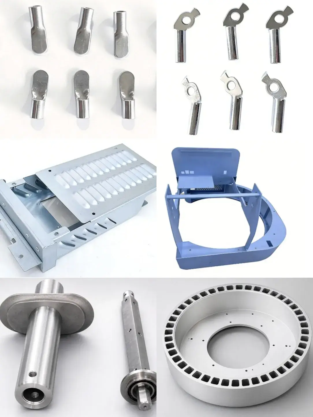
Unterstützung vielfältiger Engineering- und Fertigungsanwendungen.
-
Wettbewerbsfähige Preise & DFM
-
Technischer Support rund um die Uhr
-
Schnelle Bearbeitung, kurze Lieferzeiten, keine Mindestbestellmenge
Zertifizierungen auf Anfrage prüfen: ISO 9001:2015 | IATF 16949:2016

über Chuangkai
Zhejiang Chuangkai Mechanical and Electrical Technology Co., Ltd. wurde im März 2003 mit einem Stammkapital von 15 Millionen RMB gegründet. Das Unternehmen ist ein Hightech-Unternehmen, das die Konstruktion und Fertigung von Präzisionswerkzeugen, Präzisionsstanzteilen, Präzisionsblechbearbeitung, Präzisionsbearbeitung, Oberflächenlackierung, Pulverbeschichtung und die Montage von Präzisionskomponenten integriert. Derzeit beschäftigt das Unternehmen 95 Mitarbeiter und verfügt über moderne Präzisionsbearbeitungsanlagen und standardisierte Werkstätten mit einer Gesamtfläche von ca. 13.500 Quadratmetern. Wir sind nach ISO 9001, IATF 16949, ISO 45001 und ISO 14001 zertifiziert.

Konstruktion und Fertigung von Präzisionsstanzwerkzeugen

Die wichtigsten Stanzmaschinen der Stanzwerkstatt sind: 18 Hochgeschwindigkeits-Präzisionsstanzpressen mit Schließkräften von 16, 25, 40, 60, 80, 110, 200 und 250 Tonnen. Die Stanzgeschwindigkeit der Präzisions-Hochgeschwindigkeitsstanzpressen beträgt bis zu 500 Hübe pro Minute.
Werkstoffe für die Stanzverarbeitung: Messing, Phosphorbronze, Berylliumbronze, Nickel-Weißkupfer sowie verschiedene Stahlsorten und Edelstahlmaterialien, Ni-Bänder, kaltgewalzter Stahl, Bandstahl (einschließlich vorplattierter), verzinkte Bleche, kohlenstoffarmer Stahl, Federstahl und andere Verbundwerkstoffe.
Präzisionsblechfertigung
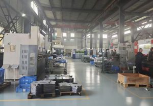
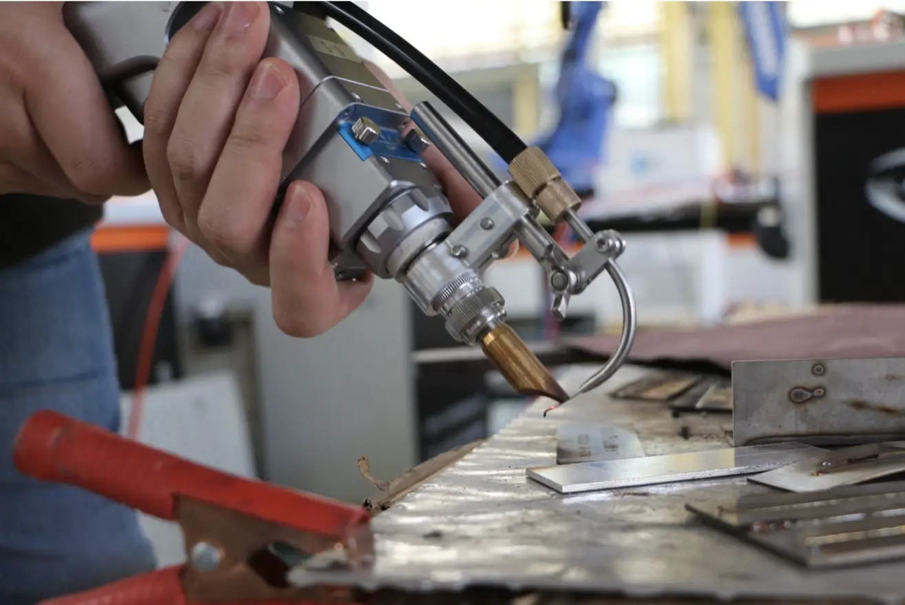
Die Blechwerkstatt ist mit Präzisions-Blechbearbeitungsmaschinen ausgestattet, darunter 2 große, hochmoderne CNC-Laserschneidmaschinen, 1 CNC-Stanzpresse, 5 CNC-Biegemaschinen sowie Nietmaschinen, Schweißmaschinen, Schleifmaschinen, Drahtziehmaschinen und andere Geräte.
Die verarbeiteten Produkte decken Bereiche wie Industrieautomation, Medizintechnik, Elektrotechnik, Verteilerkästen und weitere Anwendungsgebiete ab. Die Anlage ermöglicht Präzisionsbearbeitungen wie Schnellschneiden und Blechbearbeitung an folgenden Metallwerkstoffen: Edelstahl, Kohlenstoffstahl, Siliziumstahl, Aluminiumlegierungen, verzinktes Blech, aluminiumverzinktes Blech usw.
Pulverbeschichtung & Lackierung
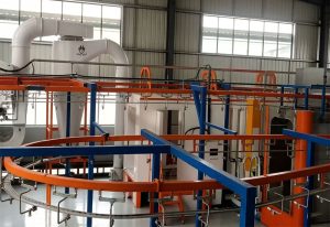
Eine automatische Pulverbeschichtungsanlage;
Eine manuelle Pulverbeschichtungsanlage (für große Teile und große Kartons);
Eine manuelle Lackierlinie (für große Teile und große Kartons);
Eine automatische Hybrid-Anlage zum Pulverbeschichten und Lackieren befindet sich im Bau.
Präzisionsbearbeitung

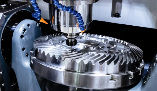
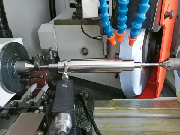
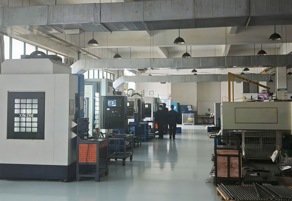
Die Bearbeitungswerkstatt ist mit Präzisionsmaschinen ausgestattet, darunter 6 Sätze 4-Achs-CNC-Maschinen, 1 Satz 5-Achs-Langdrehmaschine, 13 Sätze Präzisions-CNC-Drehmaschinen, 4 Sätze CNC-Fräsmaschinen, 16 Sätze Taiwan Mingyang Präzisions-Automatendrehmaschinen sowie Präzisions-Standarddrehmaschinen, Präzisions-3-Achs-Digital-Display-Fräsmaschinen, Präzisions-Tischdrehmaschinen, Taiwan Jizuan automatische Kantenfräsmaschinen, Präzisions-Gewinderollmaschinen, Gewinderollwerkzeuge, Präzisions-Gewindeschneidmaschinen, Präzisions-Digital-Display-Fräsmaschinen aus Taiwan, Präzisions-Messerschleifmaschinen, Innen- und Außenrundschleifmaschinen, spitzenlose Schleifmaschinen, Sägemaschinen, Ultraschallreinigungs- und Trocknungsanlagen, Poliermaschinen, Elektroschweißgeräte, Lichtbogenschweißgeräte und andere Ausrüstung.
unser
Intro-Video
unsere lustigen Fakten
Keine Koordination von mehr als 5 Lieferanten mehr. Kosteneffiziente Produktion: Vertikale Integration + Prozessoptimierung = 15–30 % Kostenreduzierung im Vergleich zu fragmentierten Lieferketten.
Schnellere Markteinführung: Simultane Produktentwicklung verkürzt die Durchlaufzeiten um 40 %. Termine werden eingehalten, ohne Kompromisse bei der Qualität einzugehen.
Fordern Sie eine kostenlose DFM-Analyse an: Laden Sie Ihre Zeichnungen/Muster hoch. Unsere Ingenieure ermitteln innerhalb von 48 Stunden Kosten- und Effizienzoptimierungspotenziale.

Das Unternehmen ist aufgebaut
0
Grundkapital
0M
Personal
0+
Fabrikgelände
0+
unser Fall
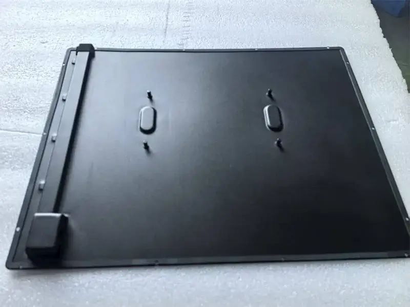
Streckverfahren als Ersatz für Schweißen + Polieren + Spachtelmasse-Abschaben
Streckverfahren als Alternative zu Schweißen und Polieren verwenden +Spachtelmasse abkratzen Technologie
Überwinden Sie den technischen Engpass und entwickeln Sie hochwertige und preisgünstige Metallstrukturbauteile für Lehr- und Demonstrationsgeräte:
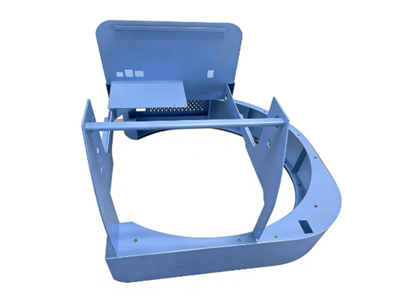
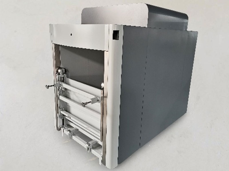
Bei der Entwicklung eines großen Demonstrationscomputers für Schulungs- und Lehrzwecke stieß ein Kunde auf erhebliche Probleme mit den zentralen Metallstrukturbauteilen. Die ursprüngliche Konstruktion sah Schweißarbeiten für die hervorstehenden Teile vor, doch die mangelhafte Schweißnahtfestigkeit führte in der Produktprüfung dazu, dass das Produkt den entscheidenden Test nicht bestand. Gleichzeitig verteuerten die hohen Kosten des Schweißverfahrens die Bauteile deutlich im Vergleich zu Wettbewerbern, der Liefertermin war knapp, und der Kunde stand unter enormem Druck hinsichtlich Qualität und Kosten.
Schwachstellen präzise lokalisieren und schnell reagieren, um sie zu beheben:
Nachdem wir die Problematik des Kunden verstanden hatten, stellten wir umgehend ein spezialisiertes technisches Team zusammen. Im ersten technischen Seminar analysierten wir eingehend die Ursachen für die mangelhafte Schweißnahtdichtheit. Durch die Optimierung der Schweißparameter und den Einsatz qualifizierter Schweißer konnten wir das Problem der Dichtheit zwar erfolgreich lösen und die anfänglichen Qualitätsanforderungen des Kunden erfüllen, die hohen Schweißkosten stellen jedoch weiterhin eine Herausforderung dar.
Innovativer Plan, zweigleisig:
Das technische Team gab sich damit nicht zufrieden. Nach zahlreichen internen Diskussionsrunden und engem Austausch mit den Kunden entwickelten wir eine grundlegende Lösung: Wir ersetzen das ursprüngliche Schweißverfahren durch ein integriertes Stanz- und Streckverfahren mit anschließender Politur und Spachteltechnik. Dadurch wird nicht nur das Risiko undichter Schweißnähte von vornherein eliminiert, sondern auch die Produktionskosten deutlich gesenkt und dem Produkt neue Marktchancen eröffnet.
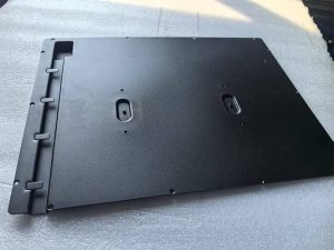
Ergreife das Unmögliche, erfülle das Versprechen:
Kundenfeedback hat die Stanzung berücksichtigt. Der Plan wurde erweitert, andere Anbieter hielten ihn jedoch für nicht umsetzbar. Angesichts dieser Bedenken sind wir fest davon überzeugt, dass man durchs Tun lernt. Basierend auf unserer umfassenden Technologieerfahrung bieten wir unseren Kunden wichtige Optimierungsvorschläge, darunter:
Passen Sie den Zugneigungswinkel an, um die Materialfließfähigkeit zu optimieren, und wählen Sie eine bestimmte Marke von kaltgewalztem Stahlblech mit besserer Zugfestigkeit.
Hervorragende Ergebnisse, von Kunden gelobt:
Nachdem der Plan festgelegt war, führten wir mehrere Runden strenger Prozesstests und Stichprobenprüfungen durch. Die gelieferten Teile entsprachen perfekt den Designanforderungen und Leistungsstandards des Kunden. Der Kunde war mit dem Ergebnis äußerst zufrieden und lobte das Produkt in höchsten Tönen: „Das ist das perfekte Produkt für mein Wunschdesign!“ Er bedankte sich außerdem herzlich beim Chuangkai-Team für die Fähigkeit, schwierige Probleme zu lösen. Wir haben dem Kunden erfolgreich geholfen, die dringende Lieferzeit einzuhalten, gleichzeitig schwierige Qualitäts- und Kostenprobleme zu lösen und seinen Produkten einen Wettbewerbsvorteil zu verschaffen.
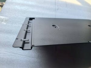
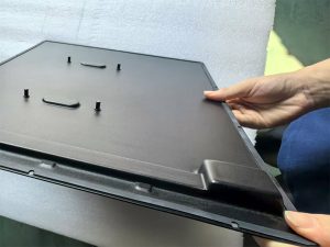
Überwindung technischer Hürden zur Lieferung hochwertiger, kostengünstiger Metallkomponenten für Bildungsdisplaysysteme
Die Herausforderung:
Ein Kunde, der große Demonstrationscomputer für Schulungs- und Bildungszwecke entwickelte, stand vor kritischen Problemen mit einem zentralen Metallbauteil. Der ursprüngliche Entwurf sah geschweißte Vorsprünge vor. Bei Produkttests führte jedoch eine mangelhafte Schweißnahtdichtigkeit zu Ausfällen. Erschwerend kam hinzu, dass die hohen Kosten des Schweißprozesses das Bauteil deutlich teurer machten als die Produkte der Konkurrenz. Angesichts der nahenden Projektfristen stand der Kunde unter enormem Druck, sowohl die Qualitäts- als auch die Kostenprobleme zu lösen.
Unsere schnelle Reaktion & erste Lösung:
Nachdem wir von dem Problem des Kunden erfahren hatten, bildeten wir umgehend eine spezialisierte technische Arbeitsgruppe. In der ersten technischen Überprüfung analysierten wir eingehend die Ursache des Dichtungsfehlers. Durch umfangreiche Optimierungsversuche der Schweißparameter und den strategischen Einsatz von Roboterschweißen erreichten wir die geforderte Dichtungsintegrität und erfüllten somit die Qualitätsvorgaben des Kunden.
Die tieferliegenden Probleme erkennen & Innovationen vorschlagen:
Das unmittelbare Dichtungsproblem war zwar gelöst, doch die grundlegenden, prohibitiven Fertigungskosten blieben bestehen. Unser Team gab sich mit dieser Lösung nicht zufrieden, führte intensive interne Brainstormings durch und stand in engem Kontakt mit dem Kunden. Wir schlugen eine bahnbrechende Lösung vor: die Schweißkonstruktion durch ein einteiliges Bauteil zu ersetzen, das durch Stanzen und Tiefziehen hergestellt wird. Dieser Ansatz versprach Folgendes:
- Die eigentliche Ursache für Dichtungsfehler beim Schweißen beseitigen.
- Erhebliche Kostensenkung durch Produktionsoptimierung.
- Steigerung der Wettbewerbsfähigkeit des Endprodukts des Kunden**.
Das „Unmögliche“ durchbrechen:
Der Kunde gab an, zuvor bereits das Stanzen geprüft zu haben, andere Lieferanten hätten dies jedoch für dieses Bauteil als nicht realisierbar eingestuft. Getreu unserem Motto „Praxis beweist es“ nutzten wir unsere technische Expertise, um entscheidende Designoptimierungen vorzuschlagen:
- 1. Anpassen des Ziehwinkels zur Verbesserung des Materialflusses.
- 2. Spezifizierung eines höherwertigen kaltgewalzten Stahls mit überlegenen Tiefzieheigenschaften.
Das erfolgreiche Ergebnis:
Nach sorgfältiger Prototypentwicklung und Validierungstests auf Basis unseres optimierten Designs lieferten wir die finale Komponente. Die Ergebnisse waren herausragend und entsprachen perfekt den Designvorgaben und Leistungsanforderungen des Kunden. Der Kunde zeigte sich äußerst zufrieden und lobte das Produkt in höchsten Tönen: „Das ist genau das Produkt, das ich mir in meinem Design vorgestellt habe!“ Er dankte ChuangKai ausdrücklich für die Lösung seiner hartnäckigen technischen Herausforderung. Wir ermöglichten es dem Kunden, seinen wichtigen Liefertermin einzuhalten und gleichzeitig sowohl den Qualitätsmangel als auch die Kostenbarriere zu überwinden, wodurch die Wettbewerbsfähigkeit seiner Produkte deutlich gesteigert wurde.
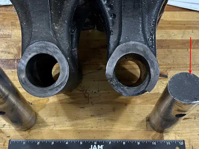
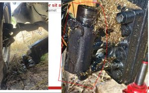
Fallstudie zu Verbesserungen bei Wellenbrüchen in Landmaschinen
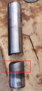
Im Juli 2024 meldete ein Kunde, dass die Achse seines Mähdreschers während des Feldeinsatzes gebrochen war. Die Endkunden waren sehr besorgt, da die Ernte des reifen Getreides dadurch beeinträchtigt wurde. Zunächst vermuteten sie, dass das Rohmaterial der Welle (40CrNiMoA) oder der Wärmebehandlungsprozess nicht den Anforderungen entsprochen haben könnte. Wir erhielten ihre Hilfe. Die gebrochene Achse wurde zunächst analysiert, und es wurde festgestellt, dass es sich nicht um ein Problem mit den Rohmaterialien oder dem Prozess handelte, sondern um ein vom Kunden konstruiertes Problem. Die Saison wurde nicht berücksichtigt, und die komplexen Betriebsbedingungen der Anlage sowie die einseitige Kraftermüdung bergen versteckte Gefahren. Die vom Kunden geforderte Wärmebehandlung mit hohem Härtegrad führt zu einer hohen Kernhärte, wodurch Ermüdungsbrüche leicht entstehen können. Nach der Analyse schlugen wir vor, die ursprüngliche Wärmebehandlung durch ein Verfahren mit induktiver Härtung zu ersetzen, das die Qualität und Oberflächenhärte optimiert. Dieses Verfahren reduziert die Kernhärte und sorgt für eine hohe Oberflächenhärte, was die Verschleißfestigkeit erfüllt. Wir lieferten das Produkt gemäß dem vorgeschlagenen Verfahren an den Kunden. Das neue Muster erzielte im zweiten Feldversuch hervorragende Ergebnisse und erhielt positives Feedback.
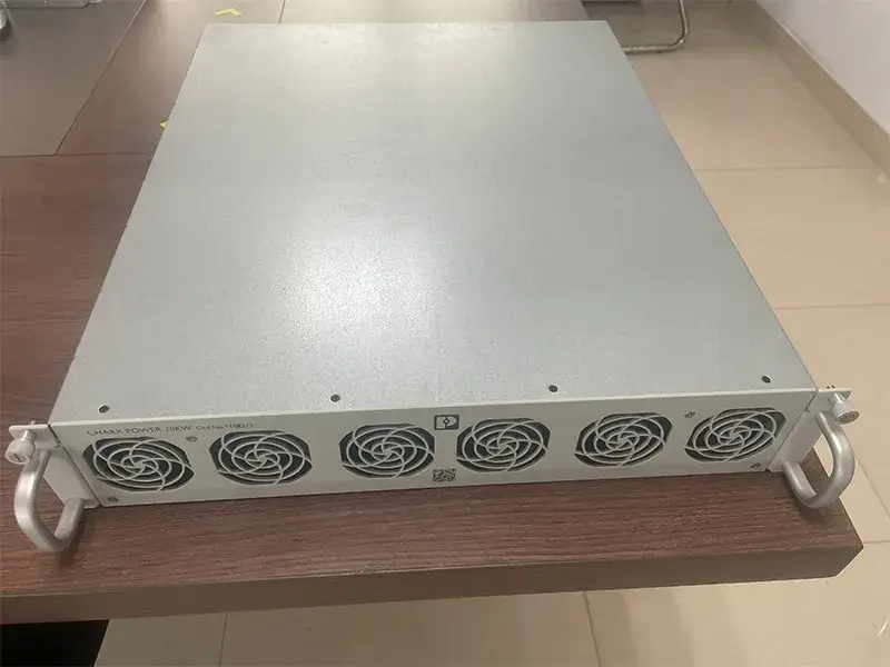
Verbesserungsprozess des Netzteilgehäuses
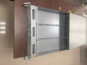
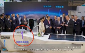
Ein deutscher Kunde unseres Unternehmens hatte Schwierigkeiten bei der Konstruktion einer Kombinationsbox. Bei Verwendung von Nieten würde die Box über die Fläche hinausragen und die Funktion beeinträchtigen. Schweißen hingegen entspräche optisch nicht den Anforderungen und wäre zu teuer. Nachdem er uns kontaktiert hatte, erfuhr er von erfolgreichen Projekten mit dieser Lösung. Wir konnten das Problem des Kunden optimal mit Doppel-Flachkopfnieten und Lochnieten lösen. Wir haben dem Kunden Muster zugesandt.
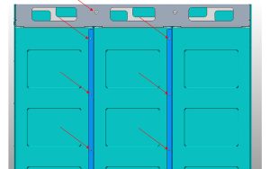
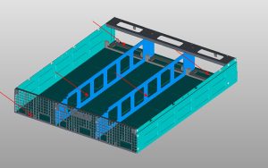
Sie waren sehr zufrieden und erzielten auf der Hannover Messe hervorragende Ergebnisse. Einstimmiges Lob!

Ihr Partner für umfassende Fertigungslösungen
Ihr Partner für umfassende Fertigungslösungen
Von der Idee bis zur Fertigstellung – Präzisionsgefertigt für globalen Erfolg
Bei ChuangKai beseitigen wir die Komplexität der Beschaffung von Komponenten mehrerer Anbieter. Als vertikal integrierter Hersteller, spezialisiert auf ODM- und OEM-Lösungen, gewährleisten wir durch unsere umfassenden Kompetenzen eine reibungslose Produktion hochpräziser Bauteile:
Integrierte Fertigungsdienstleistungen:
- Bearbeitung: CNC-Fräsen/Drehen, Langdrehen
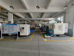
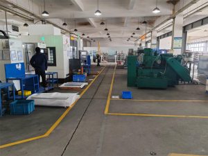
- Metallbearbeitung: Laserschneiden, Biegen, Schweißen
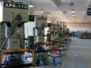
- Stanzen & Umformen: Folgeverbundstanzen, Tiefziehen
- Werkzeugbau & Formenbau: Kundenspezifische Werkzeug-/Formenkonstruktion & -fertigung
- Oberflächenbehandlung: Pulverbeschichtung, Spritzlackierung
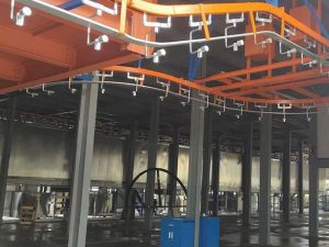
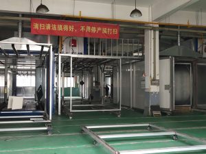
- Montage & Prüfung: Komplette Zusammenstellung, Qualitätsprüfung
ODM/OEM-Vorteile für Ihr Unternehmen:
Designinnovation
Unser Ingenieurteam arbeitet mit Ihnen zusammen, um die Konstruktionen hinsichtlich Herstellbarkeit, Kosteneffizienz und Leistung zu optimieren – und verwandelt so Konzepte in marktreife Produkte.
Rechenschaftspflicht aus einer einzigen Quelle
Die Koordination von mehr als 5 Lieferanten entfällt. Wir managen den gesamten Workflow unter einem Dach:
Design → Prototyping → Werkzeugbau → Rohmaterialbeschaffung → Produktion → Endbearbeitung → Montage → Logistik
Kosteneffiziente Produktion
Vertikale Integration + Prozessoptimierung = 15-30% Kostenreduzierung im Vergleich zu fragmentierten Lieferketten.
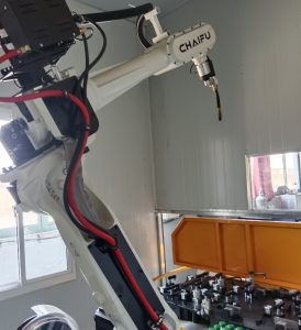
| Markteinführungsgeschwindigkeit |
Simultaneous Engineering verkürzt die Durchlaufzeiten um 40 %. Termine werden eingehalten, ohne Kompromisse bei der Qualität einzugehen.
| Integrierte Qualität |
ISO-zertifizierte Prozesse mit digitaler Rückverfolgbarkeit. PPAP-, FAIR- und CPK-Berichte verfügbar.
√ Branchen, die wir bedienen:
Automobilindustrie | Industriemaschinen | Medizintechnik | Erneuerbare Energien | Robotik | Kernenergieerzeugung
Warum sich internationale Kunden für uns entscheiden:
Problemlöser: Wie im Fallbeispiel [Unterrichtsdemonstrationsgeräte], wo wir geschweißte Baugruppen durch integrierte Stanzteile ersetzt haben – wodurch Leckagen behoben und die Kosten um 25 % gesenkt wurden.
Skalierbare Kapazität: Unterstützung von NPI-Prototypen bis hin zu Produktionsläufen mit über 1 Million Einheiten.
Technische Agilität: Mehr als 20 Ingenieure sind bereit, komplexe Herausforderungen in den Bereichen GD&T, enge Toleranzen (±0,01 mm) und Material zu meistern.
→ Fordern Sie eine kostenlose DFM-Analyse an
Laden Sie Ihre Zeichnungen/Muster hoch. Unsere Ingenieure ermitteln innerhalb von 48 Stunden Kosten- und Effizienzoptimierungspotenziale.
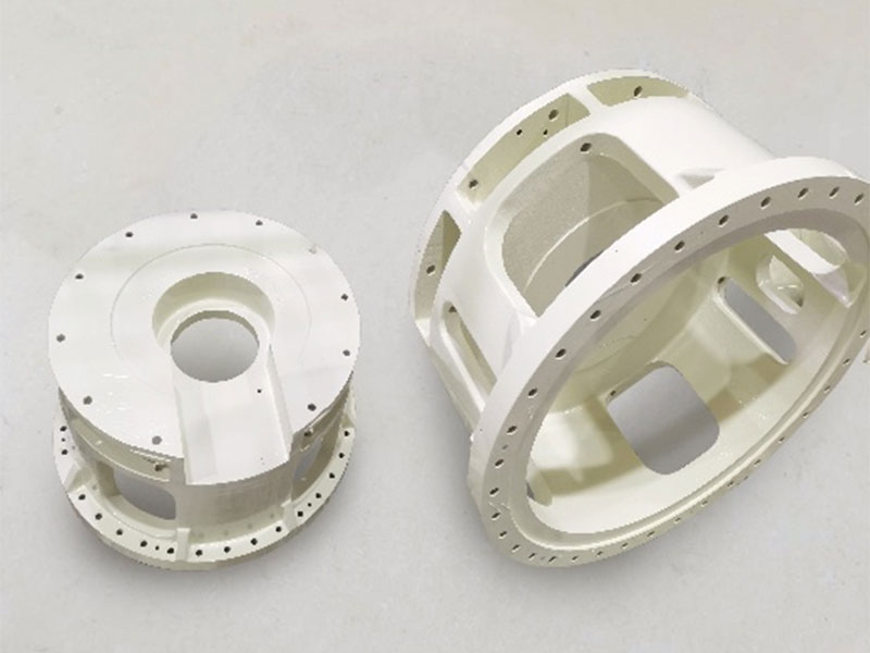
Produkte

Häufig gestellte Fragen
Dieser Abschnitt beantwortet häufig gestellte Fragen zu unseren mechanischen und elektrischen Produkten, Dienstleistungen und Richtlinien. Hier finden Sie schnell die gewünschten Informationen, ohne den Kundendienst kontaktieren zu müssen.
Unsere Kernkompetenz liegt in der Integration der gesamten industriellen Wertschöpfungskette – von der Präzisionsbearbeitung, Blechbearbeitung, Stanzproduktion, Lohnfertigung und professioneller Oberflächenbehandlung durch Spritzlackierung bis hin zur Endmontage. Dabei setzen wir ein herausragendes Qualitätsmanagementsystem im gesamten Prozess um. So müssen unsere Kunden nicht mehrere Lieferanten koordinieren, um effiziente, abgestimmte und konsistente Leistungen zu erhalten. Unsere strenge Qualitätskontrolle greift in jedem einzelnen Schritt und stellt sicher, dass wir nicht nur Teile oder Produkte liefern, die den Anforderungen entsprechen, sondern stabile, zuverlässige und hochwertige Gesamtlösungen. Dadurch helfen wir unseren Kunden, Lieferzeiten zu verkürzen, Kosten zu senken und die Effizienz ihrer Lieferkette zu verbessern.
Kundenspezifische Fertigung von Sonderbauteilen. Die Lieferzeit richtet sich nach der Komplexität des Produkts und beträgt in der Regel zwei bis vier Wochen.
25
Jahre Erfahrung


















Kontaktieren Sie uns
aktuelle Artikel
aktuelle Artikel
Benötigen Sie Lösungen im Bereich Mechanik und Elektrotechnik oder haben Sie Fragen? Nehmen Sie Kontakt mit uns auf!
Tapping vs. Thread Milling for CNC-Machined OEM Parts: Choosing the Right Internal Thread Process
23
Oktober
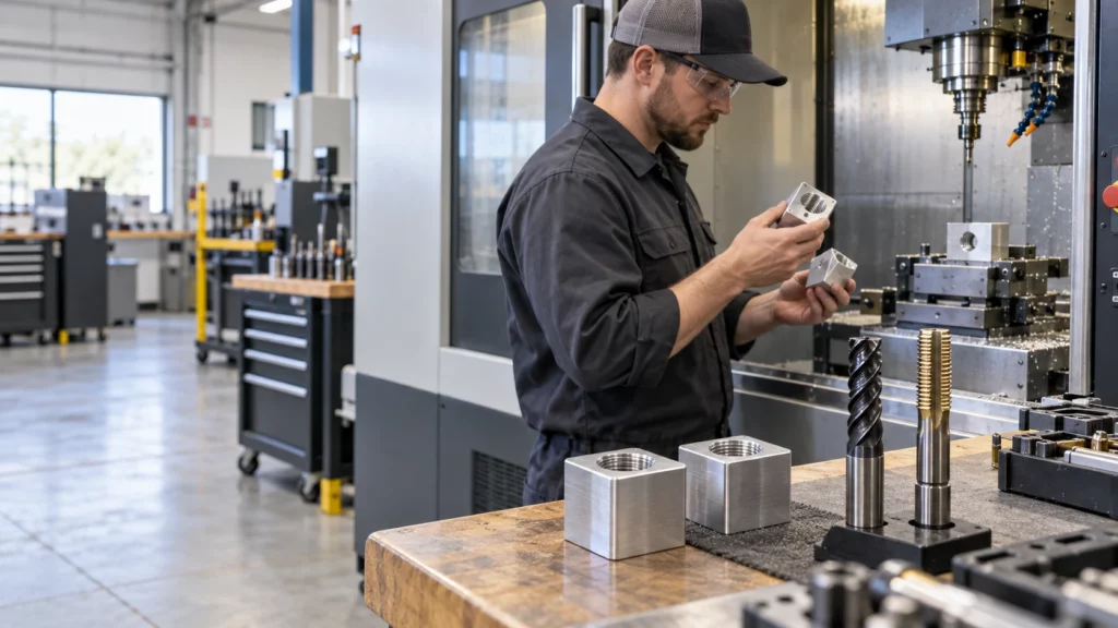
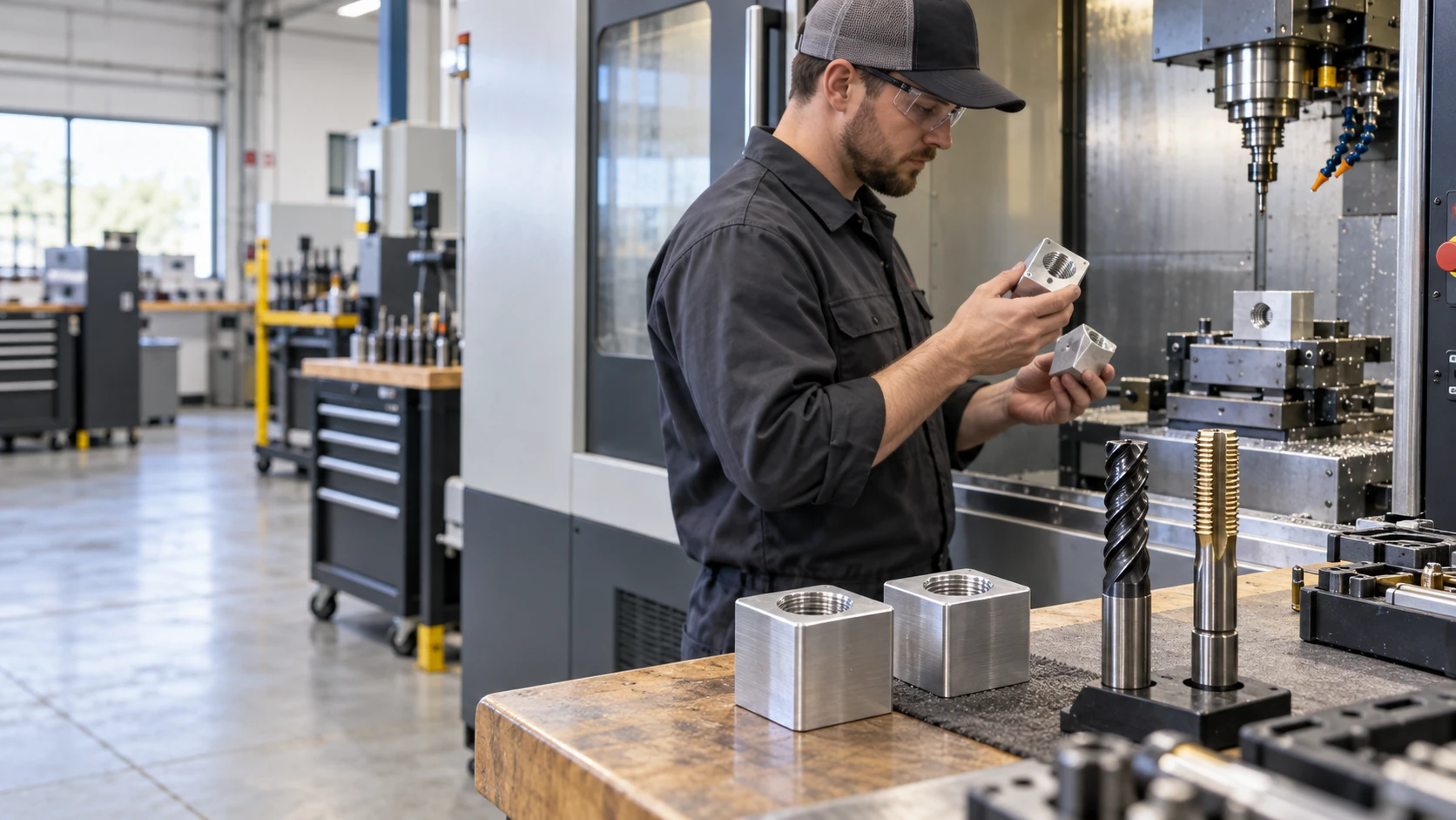
The choice between tapping and thread milling depends on the hole, material, thread specification, production quantity, machine capability, and cost of failure. Tapping is usually the faster route for repeat production of standard internal threads. Thread milling offers more control over thread size and fit, handles a wider range of diameters with fewer tools, and can reduce the consequence of a tool failure in a valuable part.
Neither process is universally better. A through-hole in a stable aluminum part may favor tapping, while a large thread, difficult material, expensive near-finished component, or close fit adjustment may justify thread milling. Blind-hole geometry and usable thread depth can change the answer again.
Tapping vs Thread Milling at a Glance
| Decision factor | Tapping | Thread milling |
| Cycle time | Often faster for standard repeated threads. | Usually longer because the tool follows a helical path. |
| Tool flexibility | One tap normally matches a specific size, pitch, and form. | One cutter may cover multiple diameters that share a compatible pitch and profile. |
| Fit adjustment | Limited after the tap and hole preparation are selected. | Tool-path offsets can adjust the finished thread within process limits. |
| Failure risk | A broken tap may be difficult to remove from the part. | A smaller cutter may be easier to recover from, but breakage can still damage the feature. |
| Machine need | Requires controlled feed and rotation appropriate to the tapping method. | Requires CNC helical interpolation, suitable control, rigidity, and access. |
How Each Process Cuts an Internal Thread
Both methods begin with a prepared hole, but their tool engagement is different. The drawing must specify the finished thread; the process planner then selects the pre-hole, tool, cutting data, and inspection route.
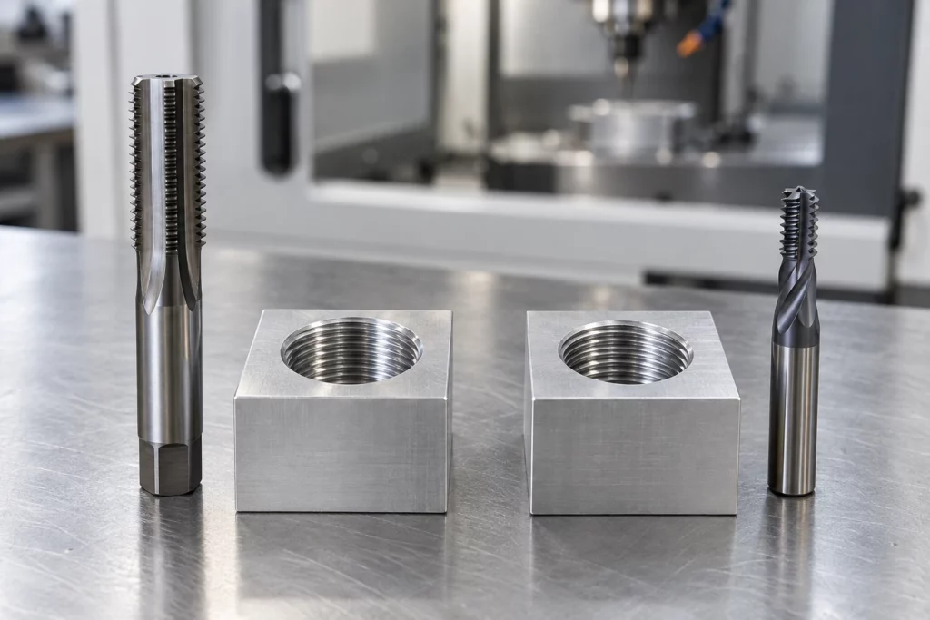
Tapping
A tap advances axially while its cutting edges or forming lobes create the complete thread profile. Because the tool engages around the circumference, torque, alignment, lubrication, chip control, and the prepared-hole diameter are important. Cut taps generate chips. Form taps displace suitable ductile material without chips, but they require a different hole size and should be approved for the material and specification.
Thread Milling
A thread mill rotates while the CNC moves it along a helical path. The cutter is smaller than the finished thread, so it engages a portion of the circumference at a time. The program controls diameter and direction, and suitable cutters can produce internal or external threads. The method needs enough bore access, tool clearance, machine interpolation, and stable workholding.
Choose by Hole Geometry
Through Holes
Through holes usually provide easier chip evacuation and fewer bottom-clearance constraints. For standard sizes and meaningful batch quantities, tapping often provides the most efficient cycle. A spiral-point cutting tap may push chips ahead through the opening when the material and application permit. Thread milling remains useful for large diameters, adjustable fits, mixed thread sizes, or parts where tool-breakage recovery influences the risk calculation.
Blind Holes
Blind holes need separate values for drilled depth, full thread depth, usable engagement, and bottom clearance. A tap has an incomplete lead before it produces full threads, and chips must have somewhere to go. Tap style, coolant delivery, chip evacuation, and reversal therefore matter. Thread milling can approach a shoulder with controlled axial positioning, but it still needs entry and exit clearance and cannot create usable thread beyond its programmed geometry. Do not specify “thread to bottom” without defining a manufacturable termination.
Choose by Material and Thread Specification
Material behavior affects torque, chips, tool wear, heat, and edge quality. Standard threads in machinable aluminum may favor tapping for speed, although chip packing or built-up edge still needs control. Tough stainless steels, high-temperature alloys, or expensive heat-treated parts may make the lower engagement and recovery advantages of thread milling more attractive. The supplier should confirm the exact alloy, hardness, and hole depth before choosing the route.
Thread size and form matter as much as material. Small standard threads may suit tapping, while larger diameters, special profiles, right- and left-hand variants, or adjustable fit classes can favor thread milling. A thread mill is not universal: its diameter, pitch capability, length, cutting form, and reach must match the feature.
Choose by Quantity and Cost of Failure
For a stable high-volume job, the shorter cycle of tapping can outweigh its lower flexibility. For prototypes and mixed families, thread milling may reduce the number of dedicated tools and allow diameter correction through offsets. The value of the workpiece also matters. Breaking a tap in an almost-complete housing can cost more than the saved cycle time; however, thread milling adds programming time and may use a more expensive cutter. Compare total route cost, not tool price alone.
Define the Thread Correctly on the Drawing
A process comparison cannot correct an incomplete specification. Use the same feature-based discipline applied to CNC machining tolerances, and include the following information:
- Thread standard and designation, nominal size, pitch or threads per inch, internal class or tolerance, and right- or left-hand direction.
- Through or blind condition, drilled depth, full thread depth, minimum usable engagement, entrance chamfer, and any bottom-clearance limit.
- Material grade and condition, heat treatment, coating or plating, quantity, critical datum relationships, and mating-fastener information.
- Inspection method, gauge standard, sampling level, first-article record, and any functional assembly test.
A complete CNC machining RFQ checklist also keeps model, drawing, revision, finish, and inspection assumptions consistent across bidders.
Verify the Sample and Production Route
Inspect the pre-hole as well as the finished thread. Confirm location, diameter, depth, chamfer, burr condition, and cleanliness. Use the specified GO and NO-GO gauges or another agreed method, then test the real mating fastener when assembly behavior matters. Record tool offsets and wear limits for thread milling, or torque, tap life, and chip-control checks for tapping. A first article should also confirm that coating, plating, or heat treatment does not invalidate the final fit.
Evaluate Supplier Capability Against the Part
CK Metal Tech publishes precision machining capabilities that include CNC milling, drilling, tapping, and related inspection resources. Its broader CNC machining services for precision metal parts provide the context for OEM process planning. The project review should still confirm whether tapping, thread milling, or another threading method is available and appropriate for the specific size, material, depth, tolerance, quantity, and inspection plan.
Abschluss
Use tapping when a standard internal thread, suitable material, controlled hole, and repeat quantity make cycle time the priority. Consider thread milling when fit adjustment, large or varied sizes, difficult materials, blind-hole constraints, or the cost of a trapped broken tap changes the economics. The drawing and sample plan should make the choice verifiable rather than leaving it to habit.
Häufig gestellte Fragen
Is Thread Milling Always More Accurate Than Tapping
No. Either process can make acceptable threads when the machine, tool, hole preparation, setup, and inspection suit the requirement. Thread milling offers useful diameter adjustment, but it does not replace process control.
Which Process Is Better for Blind Holes
It depends on usable depth, bottom clearance, material, chip control, thread size, and quantity. A suitable tap can be efficient; thread milling can improve control where evacuation or failure consequences are difficult.
Can One Thread Mill Cut Several Thread Sizes
Sometimes. A cutter may cover multiple diameters with a compatible pitch and profile, within its diameter and reach limits. Confirm the tool manufacturer’s range and the required thread form.
How Should an Internal Thread Be Inspected
Use the drawing’s specified gauge or measurement method and sampling plan. GO and NO-GO gauges are common, but depth, location, surface condition, and functional assembly may also require verification.
Can CNC-Machined Aluminum Housings Be Powder Coated? Thermal Interfaces, Fits, and Masking
22
Oktober
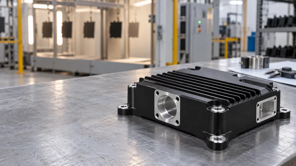
Can aluminum be powder coated after CNC machining? Yes, provided the drawing distinguishes cosmetic or protective surfaces from interfaces that must remain dimensionally, electrically, or thermally functional. A coating that performs well on an exterior wall can cause interference in a close fit, obstruct a thread, insulate a bonding point, or add thermal resistance at a heat-transfer joint.
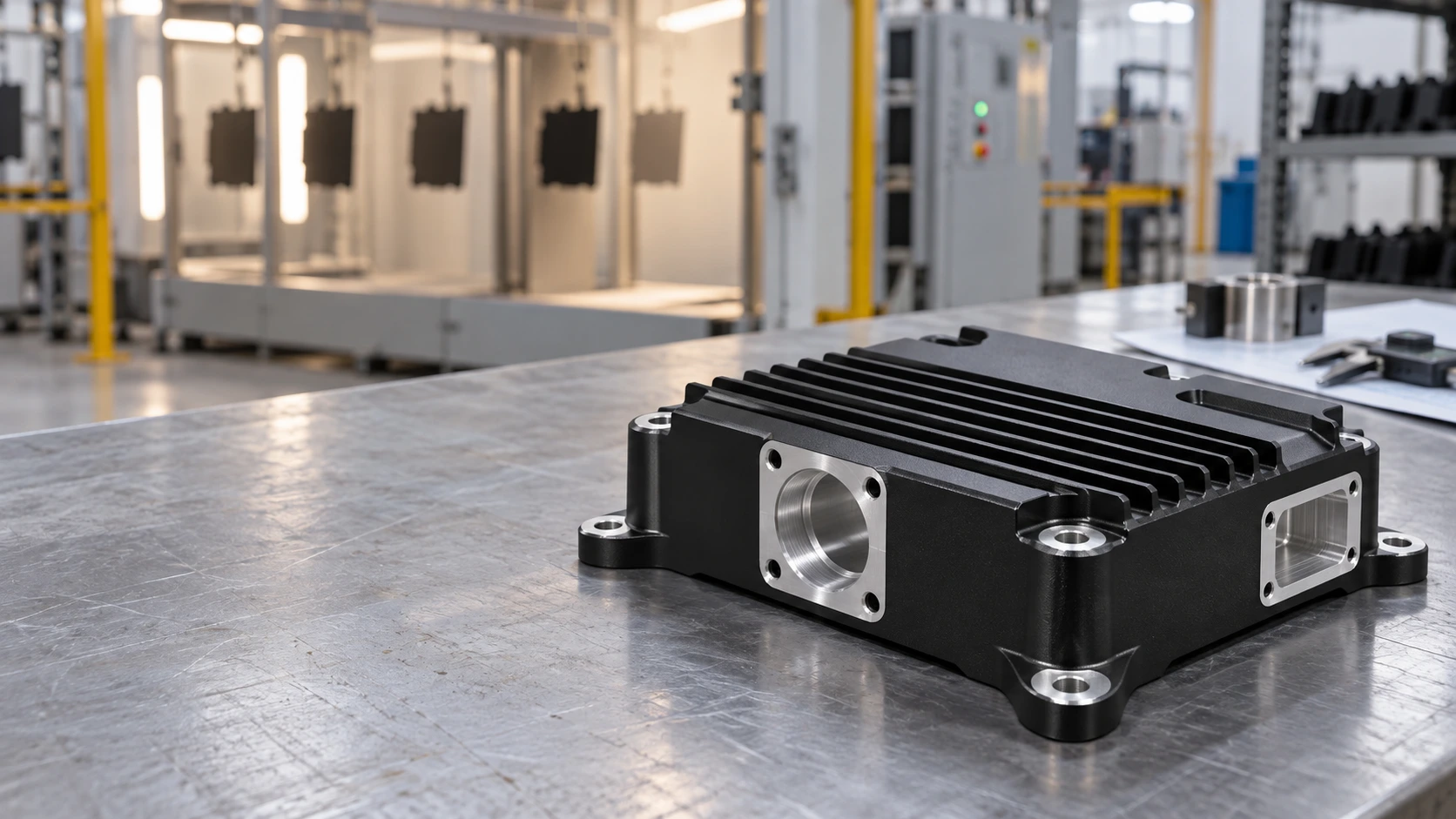
The review should therefore start with the finished assembly, not the color. CK Metal Tech’s aluminum alloy cooling and shielding cover plate illustrates why this distinction matters: one machined component may combine an exterior cover, mounting holes, grooves, structural bosses, shielding functions, and heat-dissipation duties. Those surfaces should not automatically receive the same finish treatment.
Map Functional Surfaces Before Coating
Create a finish map on the controlled drawing or model. Identify coated faces, cosmetic faces, no-coat zones, and surfaces whose final dimensions apply after finishing. A generic note such as “powder coat black” does not tell the manufacturer how the housing must assemble or perform.
Surfaces Commonly Suitable for Coating
Exterior walls, non-mating covers, guards, and handling surfaces are typical candidates when the selected pretreatment and powder system match the aluminum alloy and service environment. Coating can support appearance and surface protection, but corrosion, chemical exposure, ultraviolet exposure, and cleaning requirements still need project-specific confirmation.
Surfaces That Often Need Masking
Common no-coat candidates include bearing or bushing seats, locating datums, close-tolerance bores, sliding rails, O-ring lands, sealing faces, connector grounds, threaded holes, fastener seats, and direct thermal contact pads. The decision is functional rather than categorical: a clearance hole may tolerate film build, while a locating hole with the same nominal diameter may not.
Mask Boundaries Need Their Own Definition
A no-coat note should show where the boundary begins, which direction the mask may shift, and whether a small transition band is acceptable. This is important around countersinks, spotfaces, grooves, stepped bores, gasket lands, and thermal pads. Masking has practical placement variation, and the cured edge may not form a perfectly sharp geometric line. Keep the boundary away from a sealing path or precision datum where possible. If the transition itself affects function, dimension it from a stable feature and include it in the first-article inspection plan.
How Powder Coat Changes Functional Interfaces
Powder coating adds material to the surfaces it covers. The actual build depends on the powder, application, grounding, part geometry, racking, and cure route, so the drawing should define the finished requirement instead of assuming a universal allowance.
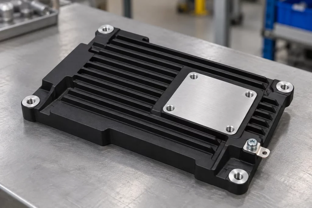
| Feature | Coating risk | Drawing or process control |
| Fits and threads | Film build reduces clearance and can obstruct engagement. | Mask, allow for the finish, or approve controlled post-coat machining. |
| Grounding points | The organic film can interrupt metal-to-metal electrical contact. | Mark bonding pads and define continuity or resistance verification. |
| Thermal interfaces | The coating and any trapped air can add resistance at a contact joint. | Keep direct-contact pads bare when required and define flatness, pressure, and interface material. |
| Sealing and datums | Build-up or an uneven mask edge can change seating and measurement references. | State whether dimensions apply before or after coating and locate mask boundaries. |
Fits and Threaded Features
Check each fit against its mating component and the finished-state tolerance. The same feature-level reasoning used for CNC machining tolerances applies after coating. Thread masks must protect the required diameter, lead-in, and usable depth. Forcing a screw through cured powder is not a controlled acceptance method because it can damage the finish and leave debris in the assembly.
Grounding and Thermal Contact
A designated grounding pad needs a clean boundary, a suitable fastener interface, and a defined verification method. Bare aluminum may also need a compatible protection strategy that preserves conductivity. For heat-transfer pads, evaluate coating together with contact area, surface flatness, clamping pressure, and any thermal interface material. A sample should be tested under representative heat load when temperature performance is critical.
Coordinate CNC Machining and Powder Coating as One Route
The safest sequence is established before chips are cut. Treat masking, finishing, and final inspection as part of the manufacturing plan rather than instructions added after machining.
- Review the current drawing, aluminum grade or approved alternative, functional interfaces, cosmetic zones, and operating environment.
- Machine the housing with any agreed allowance for surfaces controlled in the finished state; deburr edges without altering critical geometry.
- Clean and pretreat the part using a route compatible with the alloy, contamination condition, and specified coating system.
- Install plugs, caps, or high-temperature masking at the defined boundaries, then verify mask seating before spraying.
- Apply and cure the coating, remove masks cleanly, and inspect boundaries for lifting, chips, or unintended coverage.
- Complete only approved secondary machining or thread restoration, then clean the part and protect newly exposed aluminum as required.
An integrated review can connect the company’s precision machining capabilities with its powder coating service. The exact masking materials, post-coat operations, and inspection methods should still be confirmed for the part.
Verify the First Article Before Production
A first article should prove more than color and appearance. Use the actual mating components or representative gauges where possible, and record the drawing revision and coating specification used for approval.
- Dimensions: measure critical fits, datums, hole locations, and flatness in the state specified on the drawing.
- Assembly: install fasteners, covers, seals, rails, connectors, and locating features without forcing or finish damage.
- Electrical function: verify required bonding or shielding continuity at the specified contact points.
- Thermal function: check temperature performance under a representative load when the housing forms part of the heat path.
- Finish: inspect coverage, cure evidence, mask edges, handling damage, and cosmetic acceptance against an agreed reference.
Record nonconforming features separately. A part should not pass because its exterior looks uniform when a thread, bonding pad, thermal interface, or locating surface fails its own requirement.
What to Put in the Drawing and RFQ
Submit the 2D drawing and 3D model with material, quantity, coating system or performance requirement, color and texture, finished-state dimensions, no-coat zones, mask depth, thread callouts, grounding locations, thermal pads, inspection records, mating-part information, and sample approval criteria. Separate prototype quantity from expected production volume so the supplier can evaluate masking fixtures and process controls appropriately.
Abschluss
CNC-machined aluminum housings can be powder coated successfully when the finish map protects the part’s working interfaces. The design should preserve required clearance, thread engagement, electrical bonding, and thermal contact, while the process plan should connect machining, pretreatment, masking, coating, and finished-state inspection.
Häufig gestellte Fragen
Should Every Threaded Hole Be Masked
No. Masking depends on thread function, fastener fit, engagement depth, and the approved finishing route. The drawing should identify which threads must remain coating-free and how they will be checked.
Can Powder Coat Be Allowed for in a Close Fit
Sometimes, but the designer and manufacturer must agree on the final clearance and whether the controlling dimension applies before or after coating. Do not rely on a generic film allowance.
Should a Thermal Contact Pad Remain Bare
Often it should when direct metal contact is part of the heat path. Confirm the complete joint, including flatness, contact pressure, interface material, corrosion protection, and the required thermal test.
Is Post Coating Machining Acceptable
It may be, if the operation is planned. Control chips, protect the surrounding finish, re-inspect dimensions, and define how newly exposed aluminum will be handled.
Request a Joint Machining and Coating Review
Send CK Metal Tech the drawing revision, alloy, quantity, mating-part details, coating requirements, no-coat zones, thermal duty, grounding needs, and inspection expectations. Use the request a joint machining and coating review route to confirm the manufacturing sequence before quotation.
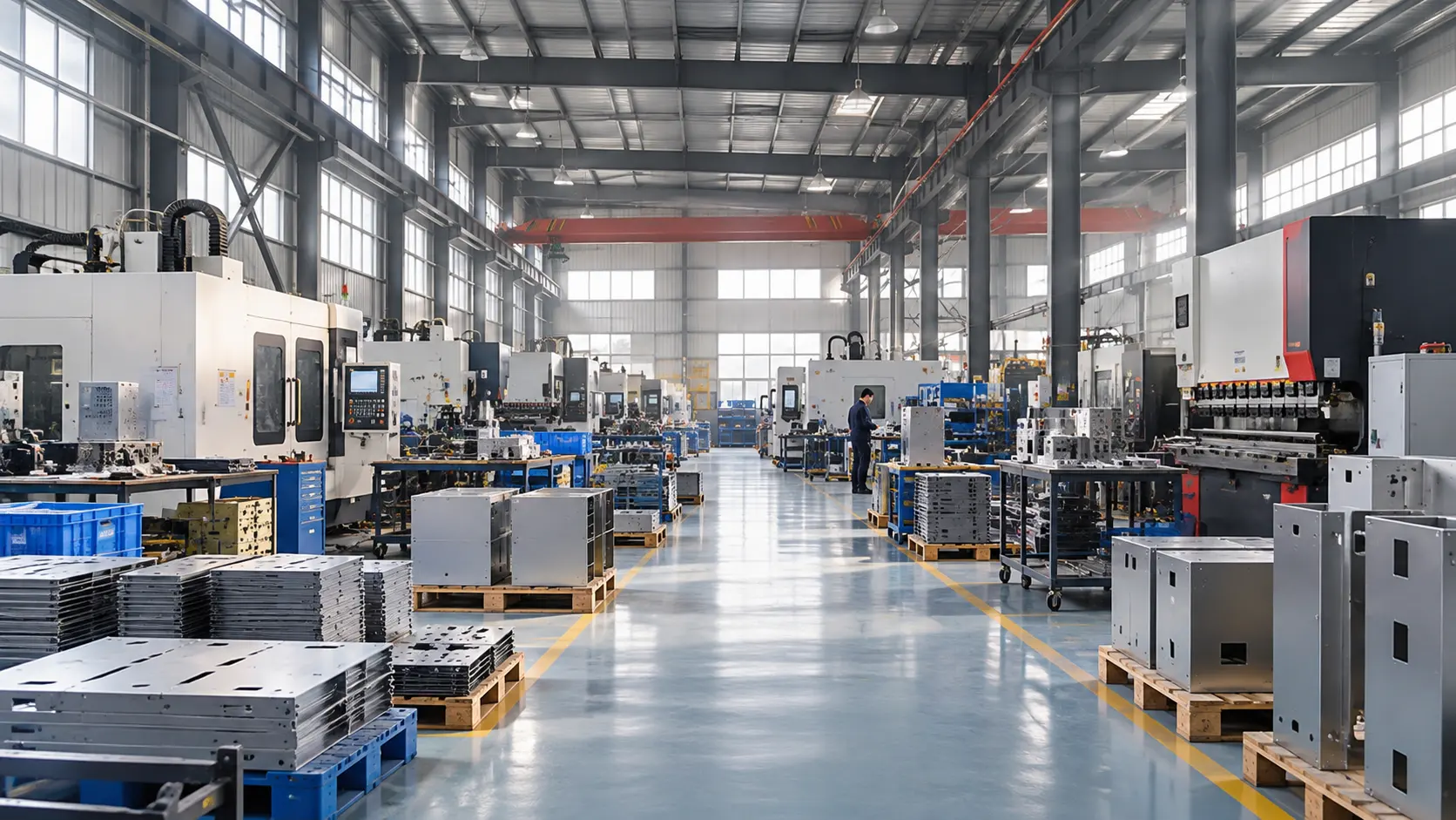
One Metal Supplier vs Multiple Vendors: How to Calculate Total Landed Cost
16
Oktober
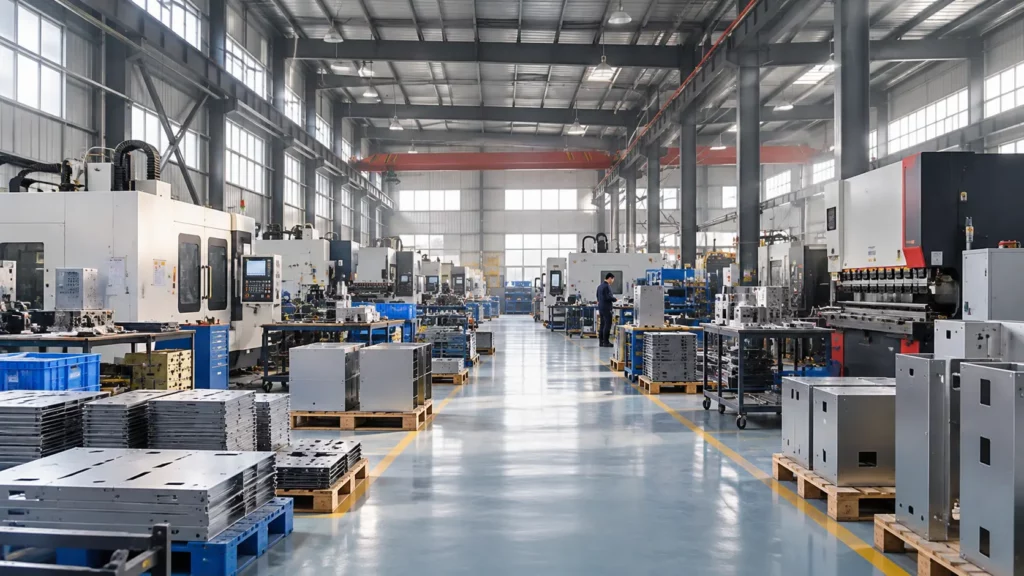
One metal supplier can reduce transfers between fabrication, finishing, and assembly, but supplier consolidation does not automatically lower total landed cost. Compare both routes at the same delivery destination, then add the buyer-side costs needed to turn delivered parts into accepted assemblies. Keep those layers separate: shipping and import charges belong in the landed-cost calculation; supplier administration, inventory, and integration costs belong in the broader sourcing decision.
For an OEM buying custom metal parts, this distinction prevents a lower piece price from hiding extra work. It also avoids calling every future operating expense a landed cost.
Define the Deliverable Before Comparing Vendors
Start with one controlled bill of materials and drawing revision. Specify material, finish, quantity, inspection criteria, packaging, destination, and assembly responsibility. A coated panel from one vendor cannot be compared directly with an assembled enclosure from another unless the missing operations are priced separately.
Distinguish process splitting from dual sourcing. Sending cutting to one shop and coating to another creates sequential handoffs. Qualifying two independent suppliers for the same finished assembly creates a backup route. These arrangements have different costs and continuity benefits; combining them under “multiple vendors” obscures the decision.
Calculate Total Landed Cost in Two Layers
The core shipment calculation is:
Landed cost = supplier invoices + separately charged tooling + packaging + freight + insurance + applicable duties, taxes, and clearance fees.
The International Trade Administration’s landed-cost guidance supports the product-plus-delivery approach. For metal parts, verify which charges are already included in each quotation. Add only costs outside the quoted scope, and use the same receiving location.
Then calculate a separate management metric:
Sourcing comparison cost = landed cost + buyer assembly and inspection + supplier administration + inventory carrying cost + evidence-based quality and disruption allowances.
This second formula is a purchasing decision tool, not a customs valuation or accounting rule. It does not include equipment operating costs over the product’s lifetime. Keep recoverable taxes and other accounting treatments identifiable for finance review rather than treating every cash payment as a permanent expense.
Normalize Quotes and Allocate Shared Charges
Use the same currency, demand period, release size, and named delivery point. Record the delivery term and which party pays each freight leg. A quote that includes shipping can appear expensive beside a factory-gate quote until the missing freight is added.
For international purchases, ask a qualified broker to verify classification, origin, applicable charges, and the relevant shipment date. Do not copy a tariff percentage from another part or last year’s order.
Allocate shared freight across a mixed shipment using a defensible driver, such as chargeable weight or occupied volume. Allocate tooling over the realistically committed program quantity, with tooling ownership shown separately. Show first-order and repeat-order costs independently; an optimistic lifetime volume can conceal a costly launch.
A Worked Example for One Thousand Assemblies
The following figures are hypothetical USD amounts, not CK Metal Tech quotations or tariff estimates. Both routes ultimately provide 1,000 accepted assemblies. The single supplier includes assembly in its invoice; the split route requires more buyer assembly work. Charges already included in supplier invoices are excluded from the other rows.
| Cost category | One supplier | Multiple vendors |
| Supplier invoices | $40,000 | $37,000 |
| Tooling and setup | $3,000 | $2,200 |
| Packaging freight and insurance | $1,800 | $3,300 |
| Illustrative import and clearance charges | $1,500 | $1,500 |
| Core landed cost | $46,300 | $44,000 |
| Buyer assembly and inspection | $800 | $3,300 |
| Supplier administration | $400 | $1,200 |
| Inventory carrying cost | $600 | $1,100 |
| Expected quality and rework allowance | $600 | $1,800 |
| Sourcing comparison total | $48,700 | $51,400 |
| Cost per accepted assembly | $48.70 | $51.40 |
Multiple vendors win the core landed-cost comparison by $2,300. After buyer-side costs are included, one supplier is lower by $2,700. This result follows the stated assumptions; it does not prove that consolidation is generally cheaper.
The decision changes if the split route reduces internal assembly effort, avoids quality losses, or provides a valuable qualified backup. Replace every allowance with program evidence before using this example for an award decision.
Measure Handoffs Without Double Counting
Map the route from cutting and forming through machining, coating, final inspection, and packing. Sheet metal fabrication may involve several linked operations, so track the transfers between them rather than counting suppliers alone.
For each handoff, record transport, protective packaging, receiving inspection, queue time, and revision-control responsibility. Estimate internal work from hours multiplied by an approved labor rate. Distinguish cash savings from staff capacity released: fewer purchase orders do not necessarily reduce payroll.
Estimate inventory carrying cost from average inventory value, the approved annual carrying rate, and the time period. Use historical rework and expedite costs where available. For a new program, show low, expected, and high cases rather than inventing a precise failure probability.
Avoid charging the same loss twice. If rejected units already reduce the accepted-unit denominator, check whether a separate scrap allowance repeats that loss. Likewise, do not add replacement freight when it is already included in a rework estimate.
Choose the Route and Test Its Weak Points
One supplier is attractive when interfaces dominate the program: welded frames must match machined brackets, coating boundaries affect fit, and completed assemblies require a coordinated release. Multiple vendors may be preferable when a process needs specialist qualification, capacity is constrained, or a genuinely independent backup is essential.
A backup is only useful if drawings, tooling access, qualification status, and available capacity make it executable. Two suppliers sharing the same critical subcontractor may still have a common interruption risk. Keep continuity requirements visible beside the cost comparison.
Test the decision against smaller releases, a rejected batch, an engineering change, and an expedited shipment. If the winner changes under a small assumption adjustment, resolve that uncertainty before committing the production route.
Request a Comparable Metal Manufacturing Quote
CK Metal Tech combines sheet metal processing, machining, stamping, powder coating, painting, and precision-component assembly. Review its metal manufacturing and assembly capabilities against the proposed route; process breadth alone does not establish capacity or suitability for a particular program.
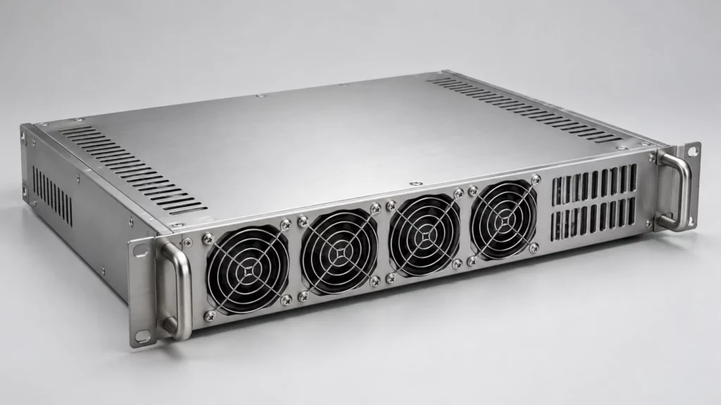
Send the BOM, controlled drawings, quantities, destination, finish requirements, and acceptance plan. Ask CK Metal Tech to separate tooling from recurring prices and identify subcontracted operations, excluded services, and packing assumptions. Give alternative vendors the same package.
Abschluss
Choose the sourcing route using both delivered cost and the work required to obtain accepted assemblies. A transparent comparison can show that multiple vendors win on landed cost while one supplier wins after integration costs, or the reverse. Award the route whose cost assumptions and continuity requirements can be verified.
Häufig gestellte Fragen
Is one metal supplier always cheaper
No. Consolidation may reduce transfers and administration, while multiple vendors can provide specialist capability or backup capacity. Compare equivalent outputs and documented costs.
Is total landed cost the same as total cost of ownership
No. Landed cost addresses acquisition and delivery. Ownership cost extends into use, maintenance, and disposal. Buyer integration costs should remain a clearly labeled comparison layer.
How should tooling be included
Show the initial tooling payment separately, then allocate it across a defensible committed quantity for the unit comparison. Record ownership, maintenance responsibility, and repeat-order assumptions.
Should supplier management time count as a saving
Include it when comparing resource demand, but distinguish released staff capacity from actual cash savings. Use measured hours and an approved rate.
Request a Sourcing Route Review
Share the current drawings, BOM, delivery location, release schedule, and assembly scope with CK Metal Tech. Request a sourcing-route review to clarify included operations and compare the assumptions behind each quotation.