







-
تصنيع النماذج الأولية بسرعة خلال 1-3 أيام، وتلبية سلسلة التوريد بمرونة واستجابة عالية.
-
التزام راسخ بالتسليم في الوقت المحدد وبجودة منتجات ممتازة باستمرار
-
خيارات مواد شاملة + مجموعة كاملة من معالجات تشطيب الأسطح وفقًا للمعايير الصناعية
-
عرض أسعار مباشر من المصنع وتفصيل تكاليف شفاف ومفتوح بالكامل
-
نظام جودة معتمد وفقًا لمعايير ISO 9001:2015 / IATF 16949:2016
-
خدمة التجميع المتكاملة الجاهزة للاستخدام: نوفر سلعًا تامة الصنع وجاهزة للاستخدام، بالإضافة إلى قطع غيار مستقلة.
خدمة متكاملة لتصنيع المعادن حسب الطلب، من النماذج الأولية إلى الإنتاج الضخم
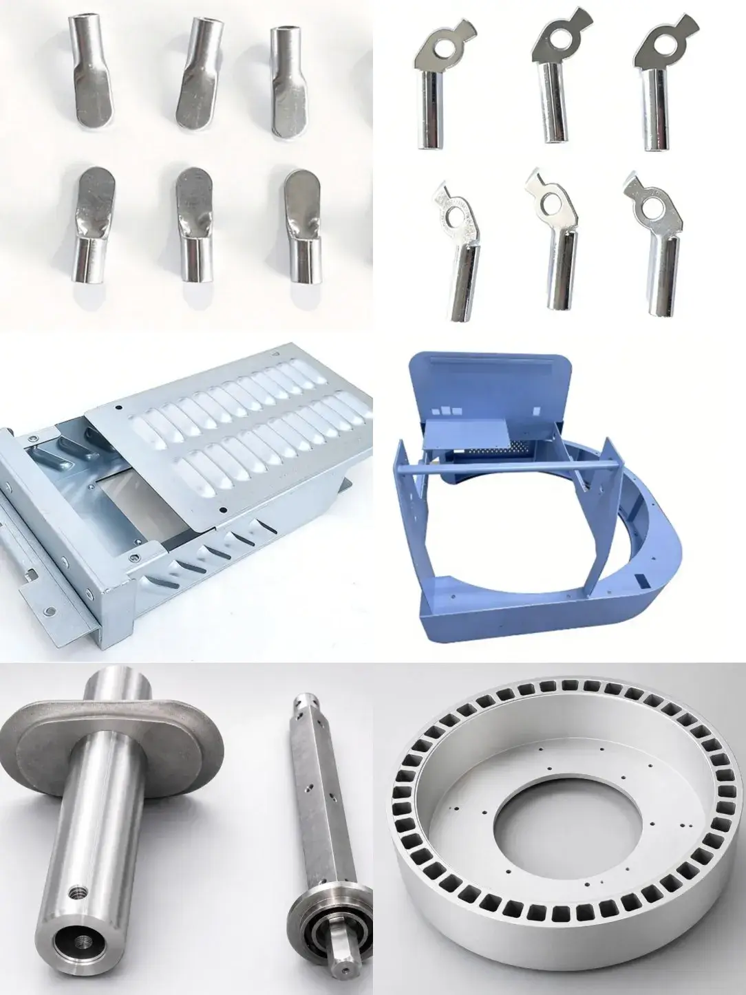
يدعم تطبيقات هندسية وتصنيعية متنوعة.
-
أسعار تنافسية وعروض مميزة في السوق
-
دعم هندسي على مدار الساعة طوال أيام الأسبوع
-
سرعة في التنفيذ، وفترة تسليم قصيرة، ولا يوجد حد أدنى للكمية المطلوبة.
التحقق من الشهادات عند الطلب: ISO 9001:2015 | IATF 16949:2016

حول تشوانغكاي
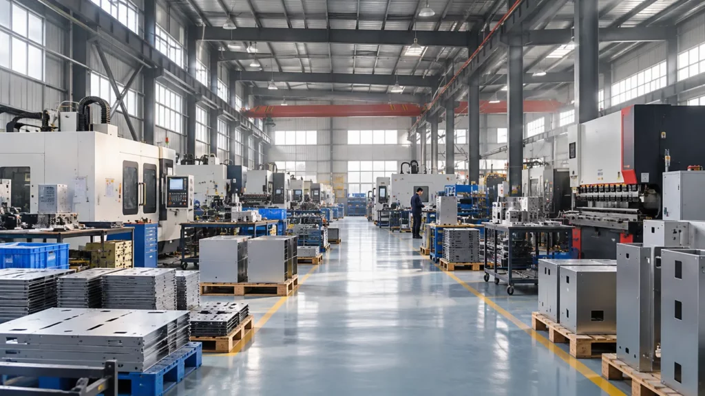
تأسست شركة تشجيانغ تشوانغكاي للتكنولوجيا الميكانيكية والكهربائية المحدودة في مارس 2003، برأس مال مسجل قدره 15 مليون يوان صيني. وهي شركة تقنية متقدمة متخصصة في تصميم وتصنيع الأدوات الدقيقة، وتشكيل المعادن الدقيق، ومعالجة الصفائح المعدنية الدقيقة، والتشغيل الآلي الدقيق، وطلاء الأسطح، والطلاء بالبودرة، وتجميع المكونات الدقيقة. ويعمل بها حاليًا 95 موظفًا، وتمتلك معدات معالجة دقيقة متطورة وورش عمل معيارية، بمساحة إجمالية تبلغ حوالي 13,500 متر مربع. وقد حصلت الشركة على شهادات أنظمة إدارة الجودة ISO9001 وIATF16949 وISO45001 وISO14001.

تصميم وتصنيع أدوات التشكيل الدقيق

معدات التشكيل الرئيسية في ورشة التشكيل: 18 مجموعة من مكابس التثقيب عالية السرعة والدقة، بمواصفات تتراوح بين 16 و25 و40 و60 و80 و110 و200 و250 طنًا. تصل سرعة مكابس التثقيب عالية السرعة والدقة إلى 500 مرة في الدقيقة.
المواد المستخدمة في عمليات التشكيل بالضغط: النحاس الأصفر، والبرونز الفوسفوري، وبرونز البريليوم، والنحاس الأبيض النيكل، بالإضافة إلى أنواع مختلفة من الفولاذ والفولاذ المقاوم للصدأ، وشرائط النيكل، والفولاذ المدلفن على البارد، وشرائح الفولاذ (بما في ذلك المطلية مسبقًا)، والصفائح المجلفنة، والفولاذ منخفض الكربون، وفولاذ الزنبرك، وغيرها من المواد المركبة.
تصنيع الصفائح المعدنية الدقيقة

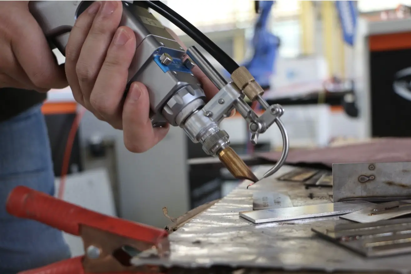
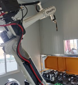
تم تجهيز ورشة الصفائح المعدنية بمعدات معالجة الصفائح المعدنية الدقيقة، بما في ذلك آلتين كبيرتين متطورتين لقطع الليزر CNC، وآلة واحدة للثقب CNC، و5 آلات ثني CNC، بالإضافة إلى آلات التثبيت، وآلات اللحام، وآلات الطحن، وآلات سحب الأسلاك، وغيرها من المعدات.
تشمل المنتجات المُعالجة مجالات الأتمتة الصناعية، والمعدات الطبية، والمعدات الكهربائية، وصناديق التوصيل الكهربائية، وصناديق التوصيل الكهربائية، وغيرها. ويمكنها إجراء عمليات معالجة دقيقة مثل القطع السريع ومعالجة الصفائح المعدنية على المواد المعدنية التالية: الفولاذ المقاوم للصدأ، والفولاذ الكربوني، والفولاذ السيليكوني، وسبائك الألومنيوم، والصفائح المجلفنة، والصفائح المطلية بالألومنيوم والزنك، وغيرها.
الطلاء بالبودرة - الطلاء
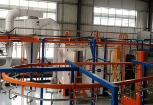
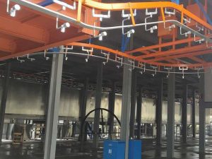
خط طلاء مسحوق آلي واحد؛
خط طلاء مسحوق يدوي واحد (للأجزاء الكبيرة والصناديق الكبيرة)؛
خط طلاء يدوي واحد (للأجزاء الكبيرة والصناديق الكبيرة)؛
خط إنتاج هجين أوتوماتيكي للطلاء بالبودرة والدهان قيد الإنشاء.
التصنيع الدقيق

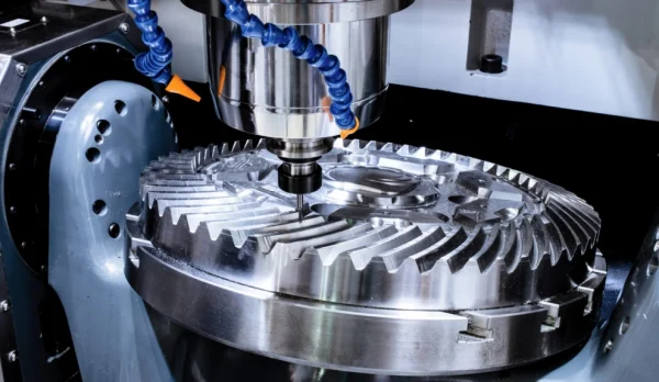
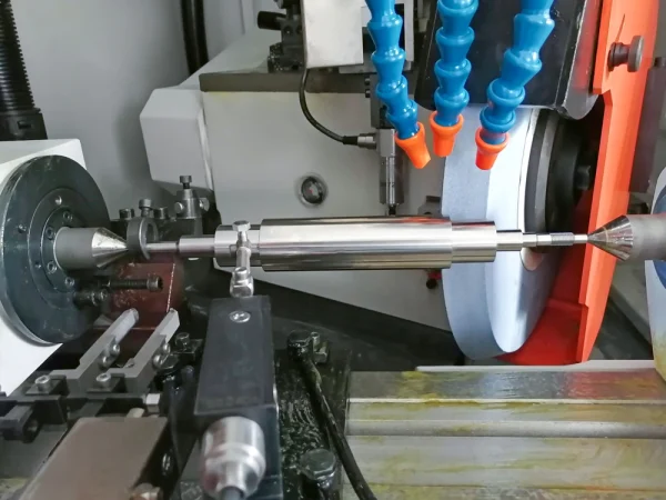
تم تجهيز ورشة التشغيل بمعدات دقيقة، بما في ذلك 6 مجموعات من آلات CNC رباعية المحاور، ومجموعة واحدة من مخرطة سويسرية خماسية المحاور، و13 مجموعة من مخارط CNC الدقيقة، و4 مجموعات من آلات التفريز CNC، و16 مجموعة من مخارط Mingyang الأوتوماتيكية الدقيقة من تايوان، بالإضافة إلى مخارط عادية دقيقة، وآلات تفريز رقمية ثلاثية المحاور دقيقة، ومخارط طاولة دقيقة، وآلات تفريز حواف أوتوماتيكية من تايوان Jizuan، وآلات درفلة خيوط دقيقة، وقوالب درفلة خيوط، وآلات تثقيب دقيقة، وآلات حفر دقيقة، وآلات تفريز رقمية دقيقة من تايوان، وآلات تجليخ سكاكين دقيقة، وآلات تجليخ أسطوانية داخلية وخارجية، وآلات تجليخ بدون مركز، وآلات نشر، وآلات تنظيف وتجفيف بالموجات فوق الصوتية، وآلات تلميع، ولحام كهربائي، ولحام قوس كهربائي، ومعدات أخرى.
ملكنا
فيديو تمهيدي
حقائقنا الممتعة
لا حاجة بعد الآن لتنسيق أكثر من 5 موردين. إنتاج ذكي من حيث التكلفة: التكامل الرأسي + تحسين العمليات = خفض التكاليف بنسبة 15-30% مقارنةً بسلاسل التوريد المجزأة.
سرعة الوصول إلى السوق: الهندسة المتزامنة تقلل أوقات التسليم بنسبة 40%. التزم بالمواعيد النهائية دون المساس بالجودة.
اطلب تحليلًا مجانيًا للتصميم من أجل التصنيع: حمّل رسوماتك/عيناتك. سيحدد مهندسونا تحسينات التكلفة والكفاءة في غضون 48 ساعة.

تم بناء الشركة
0
رأس المال المسجل
0م
طاقم عمل
0+
منطقة المصنع
0+
قضيتنا
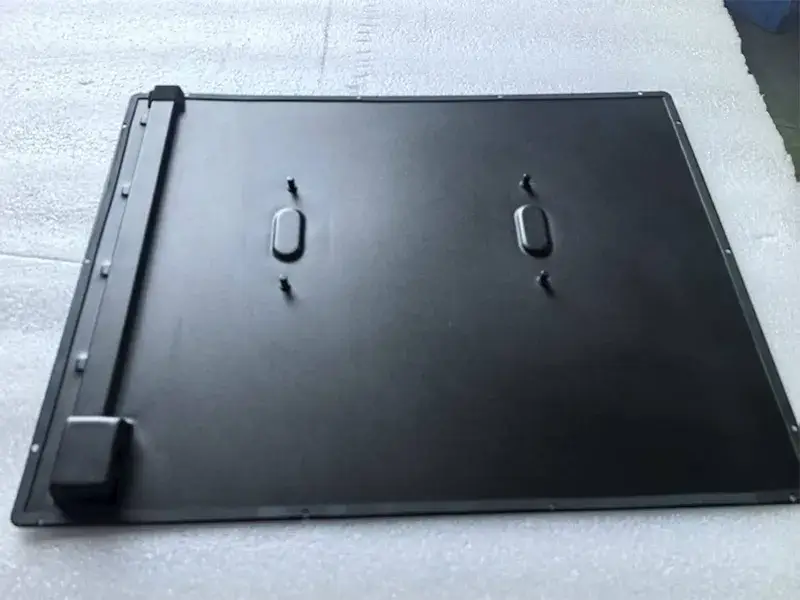
استخدم عملية التمديد كبديل لتقنية اللحام والتلميع والكشط
استخدم عملية التمديد كبديل لعملية اللحام والتلميع معجون الكشط + تكنولوجيا
تجاوز العقبات التقنية وابتكر أجزاءً هيكلية معدنية عالية الجودة وبأسعار تنافسية لمعدات العرض التوضيحي التعليمي:
عندما كان أحد العملاء يُطوّر حاسوبًا تجريبيًا كبيرًا لأغراض التدريب والتعليم، واجهت أجزاؤه المعدنية الهيكلية الأساسية تحدياتٍ جسيمة. اعتمد التصميم الأولي للجزء على عملية اللحام لتشكيل الجزء البارز، ولكن في مرحلة اختبار المنتج، أدى ضعف إحكام اللحام إلى عدم اجتياز المنتج للاختبار الرئيسي. في الوقت نفسه، أدت التكلفة العالية لعملية اللحام إلى ارتفاع سعر الأجزاء بشكلٍ ملحوظ مقارنةً بأسعار المنافسين، مع اقتراب موعد تسليم المشروع، مما وضع العميل تحت ضغطٍ كبير فيما يتعلق بالجودة والتكلفة.
تحديد نقاط الضعف بدقة والاستجابة بسرعة لمعالجتها:
بعد فهمنا لمعاناة العميل، قمنا على الفور بتشكيل فريق فني متخصص. في الندوة الفنية الأولى، حللنا بعمق السبب الجذري لضعف إحكام اللحام. ورغم أننا نجحنا، من خلال تحسين معايير اللحام وتوفير كوادر متخصصة، في حل مشكلة الإحكام وتلبية متطلبات الجودة الأولية للعملاء، إلا أن مشكلة ارتفاع تكلفة اللحام لا تزال قائمة.
خطة مبتكرة، ذات شقين:
لم يتوقف الفريق التقني عند هذا الحد. فبعد جولات عديدة من النقاشات الداخلية والتواصل الوثيق مع العملاء، اقترحنا حلاً جذرياً: استبدال عملية اللحام الأصلية بعملية متكاملة للختم والتمديد، بالإضافة إلى التلميع وكشط المعجون. هذا الحل لا يقضي تماماً على خطر عدم إحكام اللحام من جذوره فحسب، بل يقلل أيضاً بشكل كبير من تكلفة الإنتاج، ويتيح للمنتج فرصة الوصول إلى حصة سوقية أكبر.
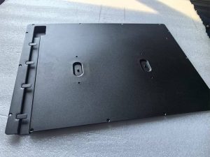
اغتنموا "المستحيل"، وحققوا الوعد:
أبدى العملاء اهتمامًا بخطة الختم والتمديد، لكن موردين آخرين أفادوا باستحالة تنفيذها. ورغم هذه التساؤلات، نؤمن إيمانًا راسخًا بأن "التعلم يكون بالممارسة". وبناءً على خبرتنا التقنية المتراكمة، نقدم لعملائنا اقتراحات أساسية لتحسين الأداء، تشمل ما يلي:
اضبط زاوية ميل الشد لتحسين سيولة المادة، واختر علامة تجارية محددة من ألواح الصلب المدرفلة على البارد ذات أداء شد أفضل.
نتائج ممتازة، نالت استحسان العملاء:
بعد تحديد الخطة، أجرينا جولات متعددة من اختبارات العمليات الدقيقة والتحقق من العينات. وقد استوفت الأجزاء النهائية المُسلّمة متطلبات التصميم ومعايير الأداء الخاصة بالعميل تمامًا. أبدى العميل رضاه التام عن النتائج، ولم يكتفِ بالإشادة قائلاً: "هذا هو المنتج المثالي لتصميمي!"، بل عبّر أيضًا عن شكره الجزيل لفريق تشوانغكاي على قدرتهم على التغلب على المشكلات الصعبة. لقد نجحنا في مساعدة العملاء خلال فترة التسليم العاجلة، مع حلّ مشكلات الجودة والتكلفة المعقدة، ومساعدتهم على اكتساب منتجاتهم ميزة تنافسية في السوق.
التغلب على العقبات التقنية لتقديم مكونات معدنية عالية الجودة وفعالة من حيث التكلفة لأنظمة العرض التعليمية
التحدي:
واجه أحد العملاء، الذي كان يطور أجهزة حاسوب تجريبية كبيرة لأغراض التدريب والتعليم، مشكلات حرجة تتعلق بأحد المكونات الهيكلية المعدنية الرئيسية. اعتمد التصميم الأولي على نتوءات ملحومة، إلا أنه خلال اختبار المنتج، تسبب ضعف إحكام اللحام في حدوث أعطال. ومما زاد الأمر تعقيدًا، أن التكلفة العالية لعملية اللحام جعلت مكونهم أغلى بكثير من مكونات المنافسين. ومع اقتراب مواعيد تسليم المشروع، كان العميل تحت ضغط هائل لحل تحديات الجودة والتكلفة على حد سواء.
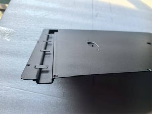
استجابتنا السريعة وحلنا الأولي:
فور علمنا بمشكلة العميل، شكلنا على الفور فريق عمل فني متخصص. في المراجعة الفنية الأولية، حللنا بدقة السبب الجذري لفشل عملية منع التسرب. ومن خلال تجارب مكثفة لتحسين معايير اللحام والتطبيق الاستراتيجي للحام الآلي، نجحنا في تحقيق سلامة منع التسرب المطلوبة، بما يفي بمواصفات الجودة الخاصة بالعميل.
تحديد المشكلة الأعمق واقتراح الابتكار:
رغم حلّ مشكلة منع التسرب المباشرة، بقيت المشكلة الأساسية المتمثلة في تكاليف التصنيع الباهظة قائمة. ورفضًا للتسوية، انخرط فريق العمل لدينا في عصف ذهني داخلي مكثف، وحافظ على تواصل وثيق مع العميل. واقترحنا حلاً جذريًا: استبدال التجميع الملحوم بمكون من قطعة واحدة مُشكّل بالختم والسحب العميق. وقد وعد هذا النهج بما يلي:
- القضاء على السبب الجذري لفشل منع التسرب المتأصل في اللحام.
- تحقيق خفض كبير في التكاليف من خلال تبسيط عملية الإنتاج.
- تعزيز القدرة التنافسية في السوق** للمنتج النهائي للعميل.
اختراق "المستحيل":
كشف العميل أنه سبق له أن درس خيار التشكيل بالضغط، لكن موردين آخرين اعتبروه غير مجدٍ لهذا الجزء. وانطلاقاً من إيماننا بأن "البرهان يكمن في التطبيق العملي"، وظّفنا خبرتنا الفنية لاقتراح تحسينات جوهرية في التصميم.
- 1- ضبط زاوية السحب لتحسين تدفق المواد.
- 2- تحديد نوع من الفولاذ المدلفن على البارد عالي الجودة يتميز بخصائص سحب عميقة فائقة.
النتيجة الناجحة:
بعد عملية تصميم نموذج أولي دقيقة واختبارات تحقق صارمة استنادًا إلى تصميمنا المُحسَّن، قمنا بتسليم المكون النهائي. كانت النتائج استثنائية، إذ توافقت تمامًا مع رؤية العميل التصميمية ومتطلبات الأداء. وقد أعرب العميل عن رضاه التام، مُشيدًا بالمنتج قائلًا: "هذا هو المنتج المثالي الذي تخيلته في تصميمي!". كما شكروا شركة تشوانغ كاي صراحةً على حل مشكلتهم التقنية المُستعصية. لقد مكّنّا العميل من الوفاء بموعد التسليم الحاسم، مع التغلب في الوقت نفسه على كلٍّ من عيب الجودة وحاجز التكلفة، مما عزز بشكل كبير القدرة التنافسية لمنتجاتهم في السوق.
دراسة حالة حول تحسينات كسر عمود الآلات الزراعية
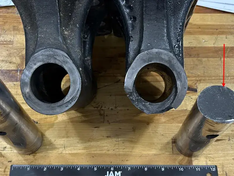
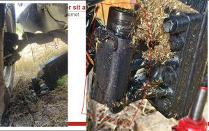
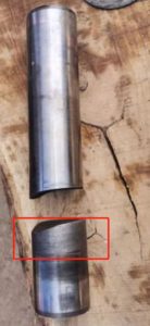
في يوليو 2024، أبلغ أحد العملاء عن حدوث كسر في محور حصادة الحبوب أثناء التشغيل في الحقل، مما أثار قلق العملاء النهائيين لعدم تمكنهم من حصاد الحبوب الناضجة بسلاسة. في البداية، اعتقدوا أن السبب قد يكون في المادة الخام للمحور (40CrNiMoA) أو في عملية المعالجة الحرارية التي لم تستوفِ المتطلبات. تلقينا مساعدتهم، وتم تحليل المحور المكسور في المرة الأولى، وخلصنا إلى أن المشكلة ليست في المواد الخام، بل في عملية التصنيع، وإنما في تصميم العميل. لم يُراعَ في التصميم ظروف التشغيل المعقدة للمعدات، بالإضافة إلى مخاطر الإجهاد الناتج عن قوة أحادية الاتجاه. تؤدي المعالجة الحرارية الشاملة ذات الصلابة العالية إلى صلابة عالية في اللب، مما يُسهّل حدوث الكسر. بعد التحليل، اقترحنا اعتماد عملية التبريد بالحث بدلاً من المعالجة الحرارية الأصلية لتحسين الجودة والسطح. تُقلل هذه العملية من صلابة اللب، بينما تُحافظ على صلابة عالية للسطح الخارجي، مما يُلبي متطلبات مقاومة التآكل. أرسلنا المنتج إلى العميل وفقًا للعملية المقترحة. حققت العينة الجديدة نتائج ممتازة في التجربة الميدانية الثانية، وقد أثمرت هذه العملية نتائج إيجابية.
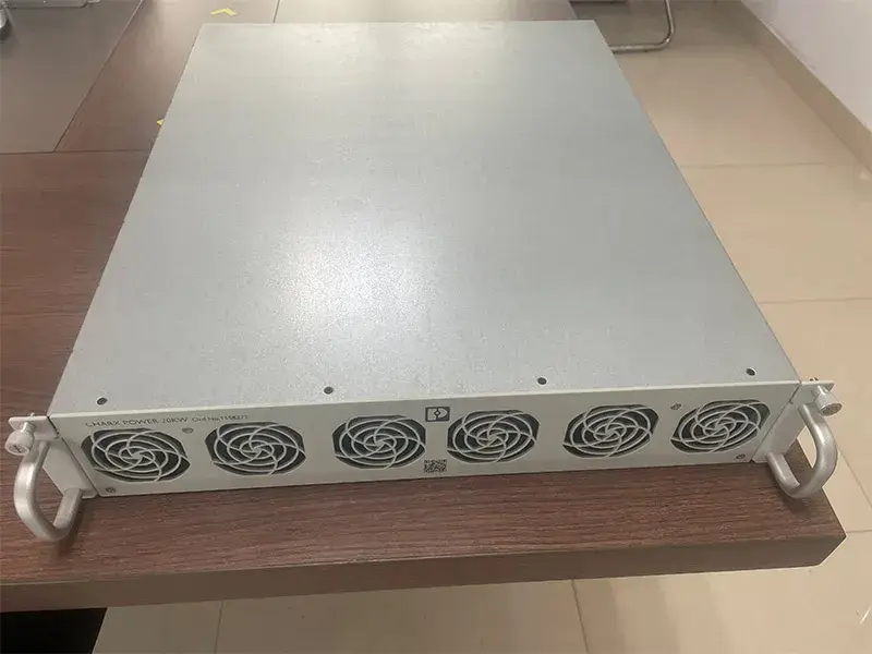
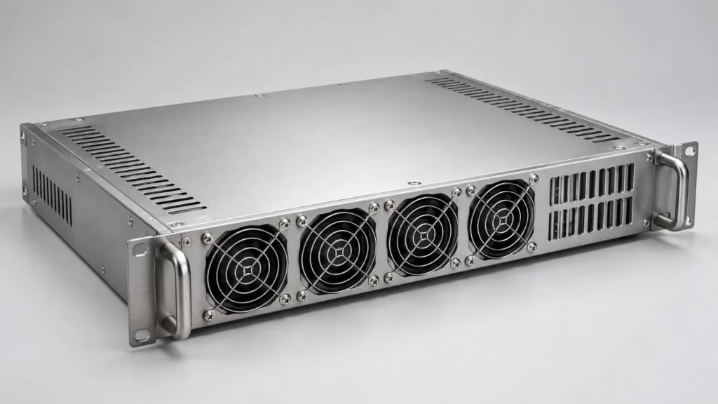
عملية تحسين غلاف صندوق إمداد الطاقة
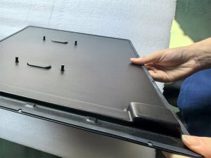
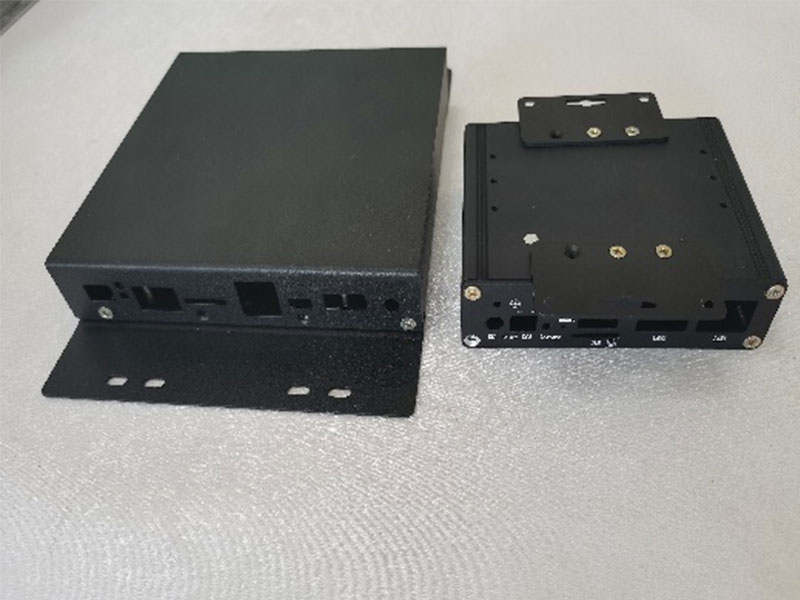
واجه أحد عملائنا الألمان صعوبة في تصميم صندوق مفاتيح متعدد الوظائف. ففي حال استخدام طريقة التثبيت بالمسامير، سيبرز الصندوق من السطح مما يؤثر على وظيفته. أما في حال استخدام طريقة اللحام، فلن يفي المظهر بالمتطلبات وستكون التكلفة مرتفعة. بعد تواصل العميل معنا، تبين لنا أننا حققنا نجاحات مماثلة في مشاريع أخرى. نستطيع حل مشاكل العملاء بكفاءة عالية باستخدام مسامير ذات رأس مسطح مزدوج وفتحات تثبيت. وقد أرسلنا عينات للعملاء.
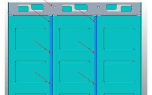
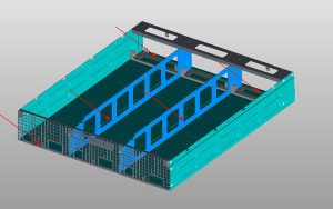
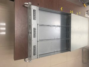
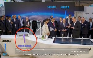
لقد كانوا راضين للغاية وحققوا نتائج باهرة في معرض هانوفر، وحظوا بإشادة بالإجماع!

شريكك في حلول التصنيع الشاملة
شريكك في حلول التصنيع الشاملة
من الفكرة إلى التنفيذ – هندسة دقيقة لتحقيق النجاح العالمي
في شركة تشوانغ كاي، نتخلص من تعقيدات التوريد من موردين متعددين. بصفتنا شركة تصنيع متكاملة رأسياً متخصصة في حلول التصميم والتصنيع الأصليين (ODM) وتصنيع المعدات الأصلية (OEM)، فإننا نقدم إنتاجاً سلساً لمكونات عالية الدقة من خلال قدراتنا الشاملة.
خدمات التصنيع المتكاملة:
- التشغيل الآلي: الخراطة/التفريز باستخدام الحاسوب، التشغيل الآلي السويسري
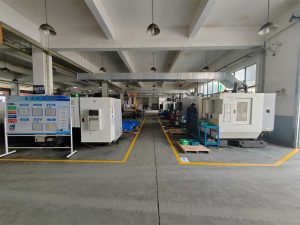
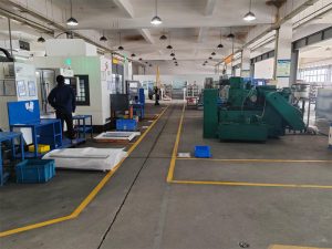
- تصنيع المعادن: القطع بالليزر، الثني، اللحام

- التشكيل والختم: الختم التدريجي بالقوالب، السحب العميق
- الأدوات والقوالب: تصميم وتصنيع القوالب حسب الطلب
- معالجة الأسطح: الطلاء بالبودرة، الطلاء بالرش
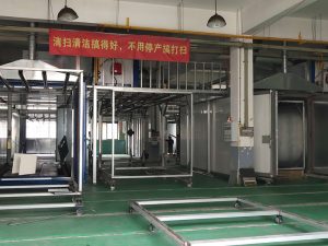
- التجميع والاختبار: تجهيز المجموعة الكاملة، التحقق من الجودة
مزايا التصميم والتصنيع الأصليين (ODM/OEM) لعملك:
ابتكار التصميم
يتعاون فريقنا الهندسي معكم لتحسين التصاميم من حيث سهولة التصنيع، وكفاءة التكلفة، والأداء - مما يحول المفاهيم إلى منتجات جاهزة للسوق.
المساءلة من مصدر واحد
وداعاً لتنسيق العمل مع أكثر من 5 موردين. نحن ندير سير العمل بالكامل تحت سقف واحد:
التصميم ← النماذج الأولية ← الأدوات ← مصادر المواد الخام ← الإنتاج ← التشطيب ← التجميع ← الخدمات اللوجستية
إنتاج ذكي التكلفة
التكامل الرأسي + تحسين العمليات = خفض التكاليف بنسبة 15-30% مقارنة بسلاسل التوريد المجزأة.
| سرعة الوصول إلى السوق |
تُقلل الهندسة المتزامنة أوقات التسليم بنسبة 40%. التزم بالمواعيد النهائية دون المساس بالجودة.
| جودة مدمجة |
عمليات معتمدة وفقًا لمعايير ISO مع إمكانية التتبع الرقمي. تتوفر تقارير PPAP وFAIR وCPK.
√ القطاعات التي نخدمها:
السيارات | الآلات الصناعية | الأجهزة الطبية | الطاقة المتجددة | الروبوتات | توليد الكهرباء النووية
لماذا يختارنا العملاء العالميون؟
حل المشكلات: مثل [حالة معدات العرض التوضيحي التعليمي] حيث استبدلنا التجميعات الملحومة بأجزاء مختومة متكاملة - حل مشكلة التسريبات + خفض التكاليف بنسبة 25٪.
قدرة قابلة للتوسع: دعم من نماذج NPI الأولية إلى عمليات إنتاج تزيد عن مليون وحدة.
القدرة التقنية: أكثر من 20 مهندسًا مستعدين للتعامل مع تحديات GD&T المعقدة، والتفاوتات الضيقة (±0.01 مم)، والمواد.
← اطلب تحليل DFM مجاني
قم بتحميل رسوماتك/عيناتك. سيقوم مهندسونا بتحديد تحسينات التكلفة والكفاءة في غضون 48 ساعة.
منتجات
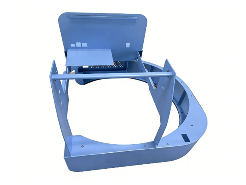
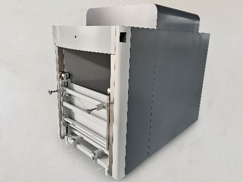
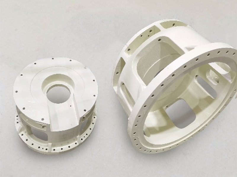
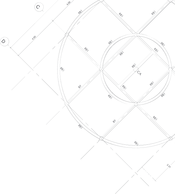
التعليمات
يجيب هذا القسم على الأسئلة الشائعة حول منتجاتنا وخدماتنا وسياساتنا الميكانيكية والكهربائية. ويساعدك على إيجاد المعلومات بسرعة دون الحاجة إلى الاتصال بالدعم الفني.
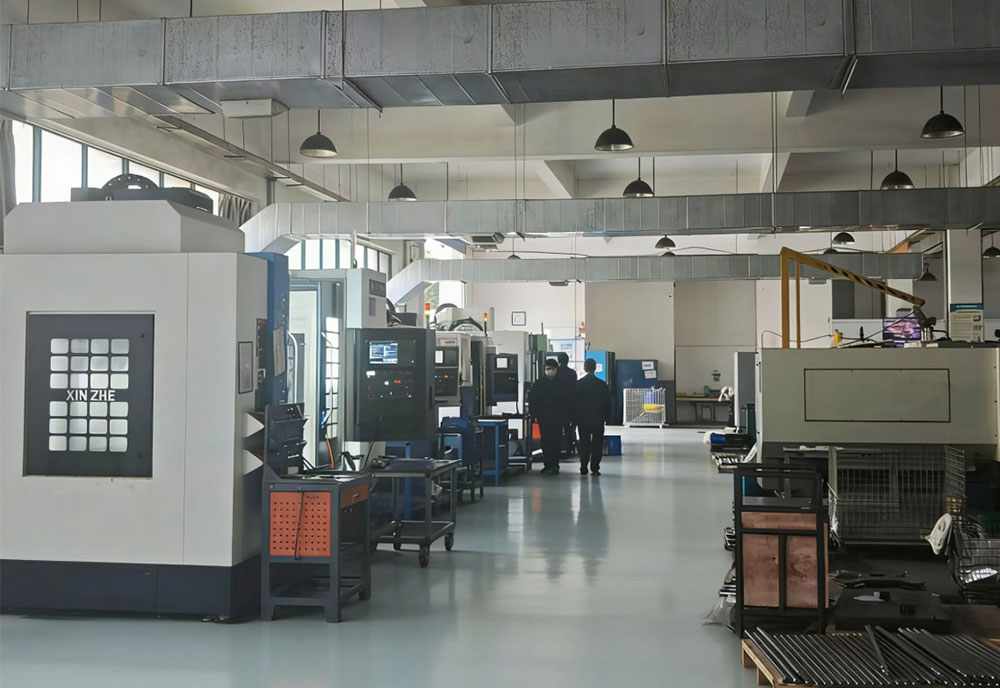
تكمن قوتنا الأساسية في تكامل سلسلة التوريد الصناعية بأكملها، بدءًا من التصنيع الدقيق، ومعالجة الصفائح المعدنية الدقيقة، وإنتاج التشكيل بالضغط، وتصميم وتصنيع القوالب، والمعالجة الاحترافية للأسطح بالرش، وصولًا إلى تجميع المنتج النهائي، مع تطبيق نظام إدارة جودة متميز في جميع مراحل العملية. هذا يعني أن العملاء ليسوا بحاجة إلى التنسيق مع موردين متعددين للحصول على خدمات فعالة ومنسقة ومتسقة. نطبق رقابة صارمة على الجودة في كل مرحلة، مما يضمن أن ما يتم تقديمه في النهاية ليس مجرد قطع غيار أو منتجات تلبي المتطلبات، بل حلول شاملة مستقرة وموثوقة وعالية الجودة، مما يساعد العملاء بفعالية على تقصير أوقات التسليم، وخفض التكاليف، وتحسين كفاءة سلسلة التوريد.
معالجة المكونات غير القياسية حسب الطلب. يعتمد ذلك على مدى تعقيد المنتج. تتراوح فترة التسليم عادةً بين أسبوعين وأربعة أسابيع.
25
سنوات الخبرة



















اتصل بنا
مقالات حديثة
مقالات حديثة
هل تحتاج إلى حلول ميكانيكية وكهربائية أو لديك استفسارات؟ تواصل معنا!
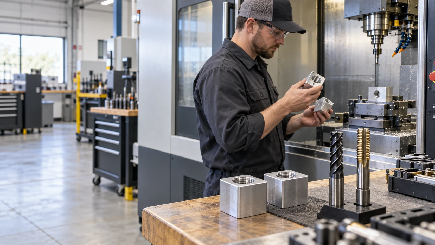
Tapping vs. Thread Milling for CNC-Machined OEM Parts: Choosing the Right Internal Thread Process
23
أكتوبر
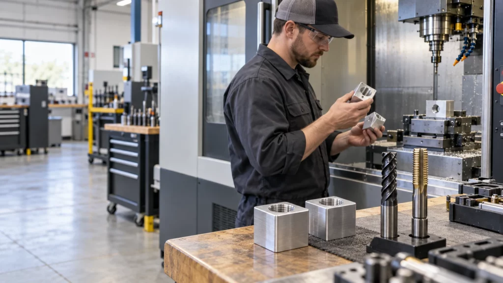
The choice between tapping and thread milling depends on the hole, material, thread specification, production quantity, machine capability, and cost of failure. Tapping is usually the faster route for repeat production of standard internal threads. Thread milling offers more control over thread size and fit, handles a wider range of diameters with fewer tools, and can reduce the consequence of a tool failure in a valuable part.
Neither process is universally better. A through-hole in a stable aluminum part may favor tapping, while a large thread, difficult material, expensive near-finished component, or close fit adjustment may justify thread milling. Blind-hole geometry and usable thread depth can change the answer again.
Tapping vs Thread Milling at a Glance
| Decision factor | Tapping | Thread milling |
| Cycle time | Often faster for standard repeated threads. | Usually longer because the tool follows a helical path. |
| Tool flexibility | One tap normally matches a specific size, pitch, and form. | One cutter may cover multiple diameters that share a compatible pitch and profile. |
| Fit adjustment | Limited after the tap and hole preparation are selected. | Tool-path offsets can adjust the finished thread within process limits. |
| Failure risk | A broken tap may be difficult to remove from the part. | A smaller cutter may be easier to recover from, but breakage can still damage the feature. |
| Machine need | Requires controlled feed and rotation appropriate to the tapping method. | Requires CNC helical interpolation, suitable control, rigidity, and access. |
How Each Process Cuts an Internal Thread
Both methods begin with a prepared hole, but their tool engagement is different. The drawing must specify the finished thread; the process planner then selects the pre-hole, tool, cutting data, and inspection route.
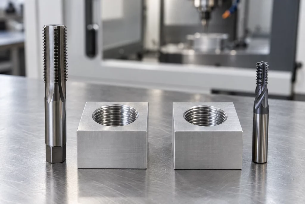
Tapping
A tap advances axially while its cutting edges or forming lobes create the complete thread profile. Because the tool engages around the circumference, torque, alignment, lubrication, chip control, and the prepared-hole diameter are important. Cut taps generate chips. Form taps displace suitable ductile material without chips, but they require a different hole size and should be approved for the material and specification.
Thread Milling
A thread mill rotates while the CNC moves it along a helical path. The cutter is smaller than the finished thread, so it engages a portion of the circumference at a time. The program controls diameter and direction, and suitable cutters can produce internal or external threads. The method needs enough bore access, tool clearance, machine interpolation, and stable workholding.
Choose by Hole Geometry
Through Holes
Through holes usually provide easier chip evacuation and fewer bottom-clearance constraints. For standard sizes and meaningful batch quantities, tapping often provides the most efficient cycle. A spiral-point cutting tap may push chips ahead through the opening when the material and application permit. Thread milling remains useful for large diameters, adjustable fits, mixed thread sizes, or parts where tool-breakage recovery influences the risk calculation.
Blind Holes
Blind holes need separate values for drilled depth, full thread depth, usable engagement, and bottom clearance. A tap has an incomplete lead before it produces full threads, and chips must have somewhere to go. Tap style, coolant delivery, chip evacuation, and reversal therefore matter. Thread milling can approach a shoulder with controlled axial positioning, but it still needs entry and exit clearance and cannot create usable thread beyond its programmed geometry. Do not specify “thread to bottom” without defining a manufacturable termination.
Choose by Material and Thread Specification
Material behavior affects torque, chips, tool wear, heat, and edge quality. Standard threads in machinable aluminum may favor tapping for speed, although chip packing or built-up edge still needs control. Tough stainless steels, high-temperature alloys, or expensive heat-treated parts may make the lower engagement and recovery advantages of thread milling more attractive. The supplier should confirm the exact alloy, hardness, and hole depth before choosing the route.
Thread size and form matter as much as material. Small standard threads may suit tapping, while larger diameters, special profiles, right- and left-hand variants, or adjustable fit classes can favor thread milling. A thread mill is not universal: its diameter, pitch capability, length, cutting form, and reach must match the feature.
Choose by Quantity and Cost of Failure
For a stable high-volume job, the shorter cycle of tapping can outweigh its lower flexibility. For prototypes and mixed families, thread milling may reduce the number of dedicated tools and allow diameter correction through offsets. The value of the workpiece also matters. Breaking a tap in an almost-complete housing can cost more than the saved cycle time; however, thread milling adds programming time and may use a more expensive cutter. Compare total route cost, not tool price alone.
Define the Thread Correctly on the Drawing
A process comparison cannot correct an incomplete specification. Use the same feature-based discipline applied to CNC machining tolerances, and include the following information:
- Thread standard and designation, nominal size, pitch or threads per inch, internal class or tolerance, and right- or left-hand direction.
- Through or blind condition, drilled depth, full thread depth, minimum usable engagement, entrance chamfer, and any bottom-clearance limit.
- Material grade and condition, heat treatment, coating or plating, quantity, critical datum relationships, and mating-fastener information.
- Inspection method, gauge standard, sampling level, first-article record, and any functional assembly test.
A complete CNC machining RFQ checklist also keeps model, drawing, revision, finish, and inspection assumptions consistent across bidders.
Verify the Sample and Production Route
Inspect the pre-hole as well as the finished thread. Confirm location, diameter, depth, chamfer, burr condition, and cleanliness. Use the specified GO and NO-GO gauges or another agreed method, then test the real mating fastener when assembly behavior matters. Record tool offsets and wear limits for thread milling, or torque, tap life, and chip-control checks for tapping. A first article should also confirm that coating, plating, or heat treatment does not invalidate the final fit.
Evaluate Supplier Capability Against the Part
CK Metal Tech publishes precision machining capabilities that include CNC milling, drilling, tapping, and related inspection resources. Its broader CNC machining services for precision metal parts provide the context for OEM process planning. The project review should still confirm whether tapping, thread milling, or another threading method is available and appropriate for the specific size, material, depth, tolerance, quantity, and inspection plan.
خاتمة
Use tapping when a standard internal thread, suitable material, controlled hole, and repeat quantity make cycle time the priority. Consider thread milling when fit adjustment, large or varied sizes, difficult materials, blind-hole constraints, or the cost of a trapped broken tap changes the economics. The drawing and sample plan should make the choice verifiable rather than leaving it to habit.
الأسئلة الشائعة
Is Thread Milling Always More Accurate Than Tapping
No. Either process can make acceptable threads when the machine, tool, hole preparation, setup, and inspection suit the requirement. Thread milling offers useful diameter adjustment, but it does not replace process control.
Which Process Is Better for Blind Holes
It depends on usable depth, bottom clearance, material, chip control, thread size, and quantity. A suitable tap can be efficient; thread milling can improve control where evacuation or failure consequences are difficult.
Can One Thread Mill Cut Several Thread Sizes
Sometimes. A cutter may cover multiple diameters with a compatible pitch and profile, within its diameter and reach limits. Confirm the tool manufacturer’s range and the required thread form.
How Should an Internal Thread Be Inspected
Use the drawing’s specified gauge or measurement method and sampling plan. GO and NO-GO gauges are common, but depth, location, surface condition, and functional assembly may also require verification.
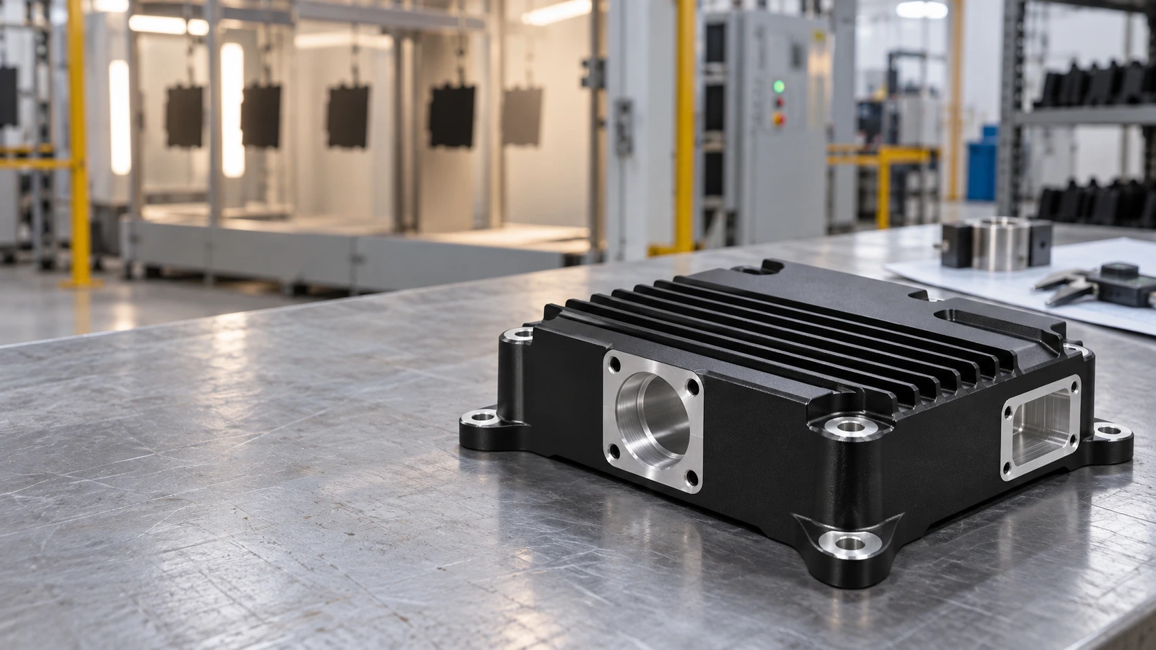
Can CNC-Machined Aluminum Housings Be Powder Coated? Thermal Interfaces, Fits, and Masking
22
أكتوبر
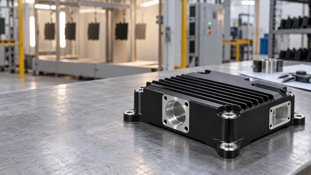
Can aluminum be powder coated after CNC machining? Yes, provided the drawing distinguishes cosmetic or protective surfaces from interfaces that must remain dimensionally, electrically, or thermally functional. A coating that performs well on an exterior wall can cause interference in a close fit, obstruct a thread, insulate a bonding point, or add thermal resistance at a heat-transfer joint.
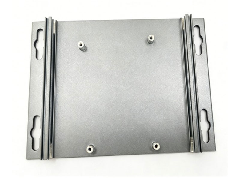
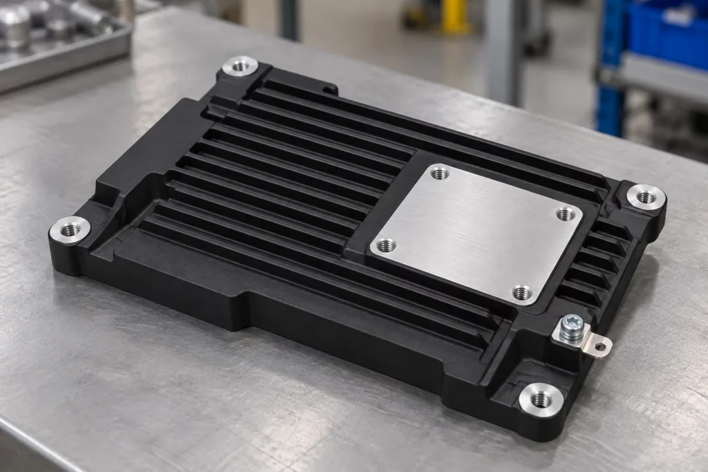
The review should therefore start with the finished assembly, not the color. CK Metal Tech’s aluminum alloy cooling and shielding cover plate illustrates why this distinction matters: one machined component may combine an exterior cover, mounting holes, grooves, structural bosses, shielding functions, and heat-dissipation duties. Those surfaces should not automatically receive the same finish treatment.
Map Functional Surfaces Before Coating
Create a finish map on the controlled drawing or model. Identify coated faces, cosmetic faces, no-coat zones, and surfaces whose final dimensions apply after finishing. A generic note such as “powder coat black” does not tell the manufacturer how the housing must assemble or perform.
Surfaces Commonly Suitable for Coating
Exterior walls, non-mating covers, guards, and handling surfaces are typical candidates when the selected pretreatment and powder system match the aluminum alloy and service environment. Coating can support appearance and surface protection, but corrosion, chemical exposure, ultraviolet exposure, and cleaning requirements still need project-specific confirmation.
Surfaces That Often Need Masking
Common no-coat candidates include bearing or bushing seats, locating datums, close-tolerance bores, sliding rails, O-ring lands, sealing faces, connector grounds, threaded holes, fastener seats, and direct thermal contact pads. The decision is functional rather than categorical: a clearance hole may tolerate film build, while a locating hole with the same nominal diameter may not.
Mask Boundaries Need Their Own Definition
A no-coat note should show where the boundary begins, which direction the mask may shift, and whether a small transition band is acceptable. This is important around countersinks, spotfaces, grooves, stepped bores, gasket lands, and thermal pads. Masking has practical placement variation, and the cured edge may not form a perfectly sharp geometric line. Keep the boundary away from a sealing path or precision datum where possible. If the transition itself affects function, dimension it from a stable feature and include it in the first-article inspection plan.
How Powder Coat Changes Functional Interfaces
Powder coating adds material to the surfaces it covers. The actual build depends on the powder, application, grounding, part geometry, racking, and cure route, so the drawing should define the finished requirement instead of assuming a universal allowance.
| Feature | Coating risk | Drawing or process control |
| Fits and threads | Film build reduces clearance and can obstruct engagement. | Mask, allow for the finish, or approve controlled post-coat machining. |
| Grounding points | The organic film can interrupt metal-to-metal electrical contact. | Mark bonding pads and define continuity or resistance verification. |
| Thermal interfaces | The coating and any trapped air can add resistance at a contact joint. | Keep direct-contact pads bare when required and define flatness, pressure, and interface material. |
| Sealing and datums | Build-up or an uneven mask edge can change seating and measurement references. | State whether dimensions apply before or after coating and locate mask boundaries. |
Fits and Threaded Features
Check each fit against its mating component and the finished-state tolerance. The same feature-level reasoning used for CNC machining tolerances applies after coating. Thread masks must protect the required diameter, lead-in, and usable depth. Forcing a screw through cured powder is not a controlled acceptance method because it can damage the finish and leave debris in the assembly.
Grounding and Thermal Contact
A designated grounding pad needs a clean boundary, a suitable fastener interface, and a defined verification method. Bare aluminum may also need a compatible protection strategy that preserves conductivity. For heat-transfer pads, evaluate coating together with contact area, surface flatness, clamping pressure, and any thermal interface material. A sample should be tested under representative heat load when temperature performance is critical.
Coordinate CNC Machining and Powder Coating as One Route
The safest sequence is established before chips are cut. Treat masking, finishing, and final inspection as part of the manufacturing plan rather than instructions added after machining.
- Review the current drawing, aluminum grade or approved alternative, functional interfaces, cosmetic zones, and operating environment.
- Machine the housing with any agreed allowance for surfaces controlled in the finished state; deburr edges without altering critical geometry.
- Clean and pretreat the part using a route compatible with the alloy, contamination condition, and specified coating system.
- Install plugs, caps, or high-temperature masking at the defined boundaries, then verify mask seating before spraying.
- Apply and cure the coating, remove masks cleanly, and inspect boundaries for lifting, chips, or unintended coverage.
- Complete only approved secondary machining or thread restoration, then clean the part and protect newly exposed aluminum as required.
An integrated review can connect the company’s precision machining capabilities with its powder coating service. The exact masking materials, post-coat operations, and inspection methods should still be confirmed for the part.
Verify the First Article Before Production
A first article should prove more than color and appearance. Use the actual mating components or representative gauges where possible, and record the drawing revision and coating specification used for approval.
- Dimensions: measure critical fits, datums, hole locations, and flatness in the state specified on the drawing.
- Assembly: install fasteners, covers, seals, rails, connectors, and locating features without forcing or finish damage.
- Electrical function: verify required bonding or shielding continuity at the specified contact points.
- Thermal function: check temperature performance under a representative load when the housing forms part of the heat path.
- Finish: inspect coverage, cure evidence, mask edges, handling damage, and cosmetic acceptance against an agreed reference.
Record nonconforming features separately. A part should not pass because its exterior looks uniform when a thread, bonding pad, thermal interface, or locating surface fails its own requirement.
What to Put in the Drawing and RFQ
Submit the 2D drawing and 3D model with material, quantity, coating system or performance requirement, color and texture, finished-state dimensions, no-coat zones, mask depth, thread callouts, grounding locations, thermal pads, inspection records, mating-part information, and sample approval criteria. Separate prototype quantity from expected production volume so the supplier can evaluate masking fixtures and process controls appropriately.
خاتمة
CNC-machined aluminum housings can be powder coated successfully when the finish map protects the part’s working interfaces. The design should preserve required clearance, thread engagement, electrical bonding, and thermal contact, while the process plan should connect machining, pretreatment, masking, coating, and finished-state inspection.
الأسئلة الشائعة
Should Every Threaded Hole Be Masked
No. Masking depends on thread function, fastener fit, engagement depth, and the approved finishing route. The drawing should identify which threads must remain coating-free and how they will be checked.
Can Powder Coat Be Allowed for in a Close Fit
Sometimes, but the designer and manufacturer must agree on the final clearance and whether the controlling dimension applies before or after coating. Do not rely on a generic film allowance.
Should a Thermal Contact Pad Remain Bare
Often it should when direct metal contact is part of the heat path. Confirm the complete joint, including flatness, contact pressure, interface material, corrosion protection, and the required thermal test.
Is Post Coating Machining Acceptable
It may be, if the operation is planned. Control chips, protect the surrounding finish, re-inspect dimensions, and define how newly exposed aluminum will be handled.
Request a Joint Machining and Coating Review
Send CK Metal Tech the drawing revision, alloy, quantity, mating-part details, coating requirements, no-coat zones, thermal duty, grounding needs, and inspection expectations. Use the request a joint machining and coating review route to confirm the manufacturing sequence before quotation.
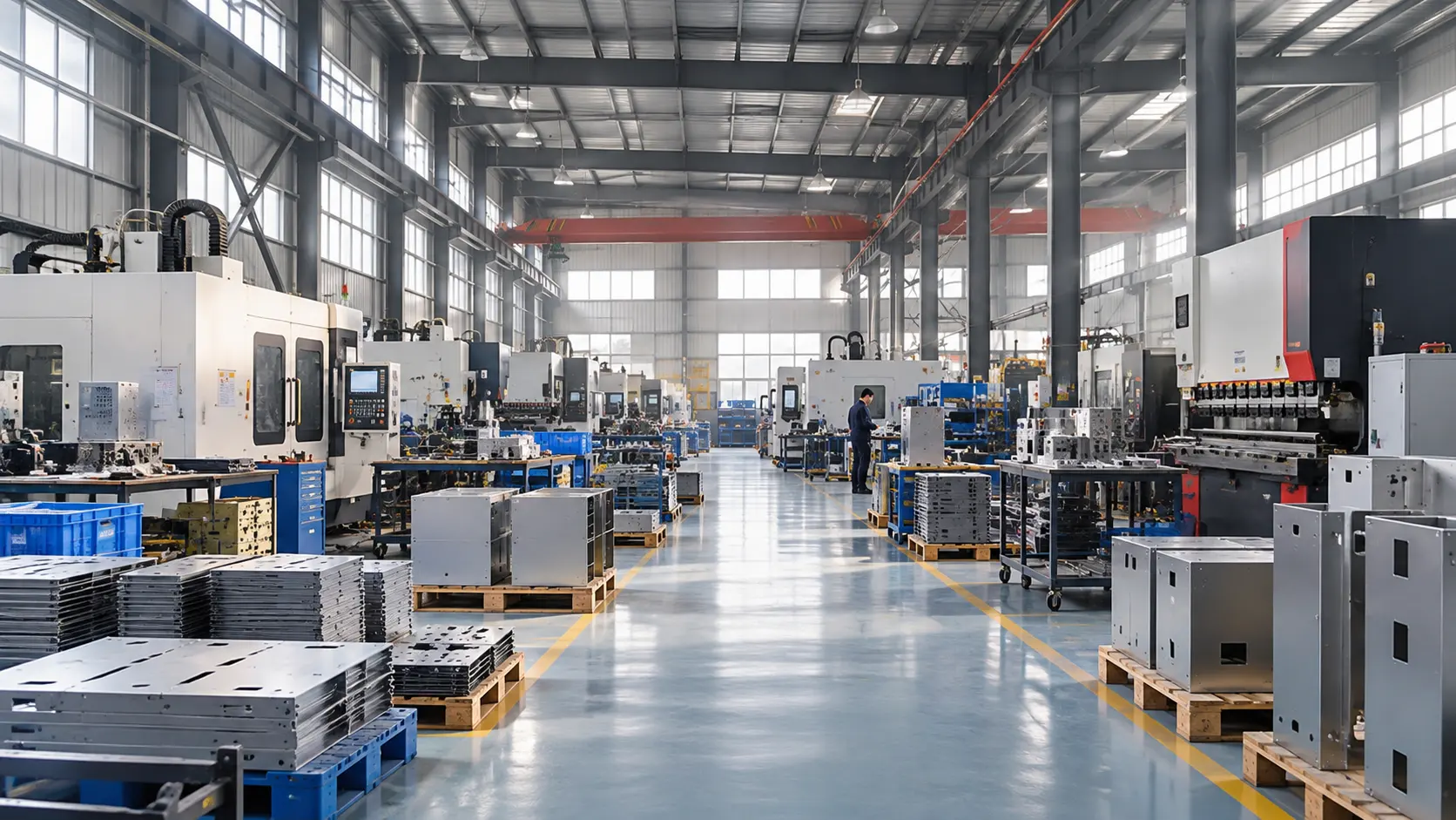
One Metal Supplier vs Multiple Vendors: How to Calculate Total Landed Cost
16
أكتوبر
One metal supplier can reduce transfers between fabrication, finishing, and assembly, but supplier consolidation does not automatically lower total landed cost. Compare both routes at the same delivery destination, then add the buyer-side costs needed to turn delivered parts into accepted assemblies. Keep those layers separate: shipping and import charges belong in the landed-cost calculation; supplier administration, inventory, and integration costs belong in the broader sourcing decision.
For an OEM buying custom metal parts, this distinction prevents a lower piece price from hiding extra work. It also avoids calling every future operating expense a landed cost.
Define the Deliverable Before Comparing Vendors
Start with one controlled bill of materials and drawing revision. Specify material, finish, quantity, inspection criteria, packaging, destination, and assembly responsibility. A coated panel from one vendor cannot be compared directly with an assembled enclosure from another unless the missing operations are priced separately.
Distinguish process splitting from dual sourcing. Sending cutting to one shop and coating to another creates sequential handoffs. Qualifying two independent suppliers for the same finished assembly creates a backup route. These arrangements have different costs and continuity benefits; combining them under “multiple vendors” obscures the decision.
Calculate Total Landed Cost in Two Layers
The core shipment calculation is:
Landed cost = supplier invoices + separately charged tooling + packaging + freight + insurance + applicable duties, taxes, and clearance fees.
The International Trade Administration’s landed-cost guidance supports the product-plus-delivery approach. For metal parts, verify which charges are already included in each quotation. Add only costs outside the quoted scope, and use the same receiving location.
Then calculate a separate management metric:
Sourcing comparison cost = landed cost + buyer assembly and inspection + supplier administration + inventory carrying cost + evidence-based quality and disruption allowances.
This second formula is a purchasing decision tool, not a customs valuation or accounting rule. It does not include equipment operating costs over the product’s lifetime. Keep recoverable taxes and other accounting treatments identifiable for finance review rather than treating every cash payment as a permanent expense.
Normalize Quotes and Allocate Shared Charges
Use the same currency, demand period, release size, and named delivery point. Record the delivery term and which party pays each freight leg. A quote that includes shipping can appear expensive beside a factory-gate quote until the missing freight is added.
For international purchases, ask a qualified broker to verify classification, origin, applicable charges, and the relevant shipment date. Do not copy a tariff percentage from another part or last year’s order.
Allocate shared freight across a mixed shipment using a defensible driver, such as chargeable weight or occupied volume. Allocate tooling over the realistically committed program quantity, with tooling ownership shown separately. Show first-order and repeat-order costs independently; an optimistic lifetime volume can conceal a costly launch.
A Worked Example for One Thousand Assemblies
The following figures are hypothetical USD amounts, not CK Metal Tech quotations or tariff estimates. Both routes ultimately provide 1,000 accepted assemblies. The single supplier includes assembly in its invoice; the split route requires more buyer assembly work. Charges already included in supplier invoices are excluded from the other rows.
| Cost category | One supplier | Multiple vendors |
| Supplier invoices | $40,000 | $37,000 |
| Tooling and setup | $3,000 | $2,200 |
| Packaging freight and insurance | $1,800 | $3,300 |
| Illustrative import and clearance charges | $1,500 | $1,500 |
| Core landed cost | $46,300 | $44,000 |
| Buyer assembly and inspection | $800 | $3,300 |
| Supplier administration | $400 | $1,200 |
| Inventory carrying cost | $600 | $1,100 |
| Expected quality and rework allowance | $600 | $1,800 |
| Sourcing comparison total | $48,700 | $51,400 |
| Cost per accepted assembly | $48.70 | $51.40 |
Multiple vendors win the core landed-cost comparison by $2,300. After buyer-side costs are included, one supplier is lower by $2,700. This result follows the stated assumptions; it does not prove that consolidation is generally cheaper.
The decision changes if the split route reduces internal assembly effort, avoids quality losses, or provides a valuable qualified backup. Replace every allowance with program evidence before using this example for an award decision.
Measure Handoffs Without Double Counting
Map the route from cutting and forming through machining, coating, final inspection, and packing. Sheet metal fabrication may involve several linked operations, so track the transfers between them rather than counting suppliers alone.
For each handoff, record transport, protective packaging, receiving inspection, queue time, and revision-control responsibility. Estimate internal work from hours multiplied by an approved labor rate. Distinguish cash savings from staff capacity released: fewer purchase orders do not necessarily reduce payroll.
Estimate inventory carrying cost from average inventory value, the approved annual carrying rate, and the time period. Use historical rework and expedite costs where available. For a new program, show low, expected, and high cases rather than inventing a precise failure probability.
Avoid charging the same loss twice. If rejected units already reduce the accepted-unit denominator, check whether a separate scrap allowance repeats that loss. Likewise, do not add replacement freight when it is already included in a rework estimate.
Choose the Route and Test Its Weak Points
One supplier is attractive when interfaces dominate the program: welded frames must match machined brackets, coating boundaries affect fit, and completed assemblies require a coordinated release. Multiple vendors may be preferable when a process needs specialist qualification, capacity is constrained, or a genuinely independent backup is essential.
A backup is only useful if drawings, tooling access, qualification status, and available capacity make it executable. Two suppliers sharing the same critical subcontractor may still have a common interruption risk. Keep continuity requirements visible beside the cost comparison.
Test the decision against smaller releases, a rejected batch, an engineering change, and an expedited shipment. If the winner changes under a small assumption adjustment, resolve that uncertainty before committing the production route.
Request a Comparable Metal Manufacturing Quote
CK Metal Tech combines sheet metal processing, machining, stamping, powder coating, painting, and precision-component assembly. Review its metal manufacturing and assembly capabilities against the proposed route; process breadth alone does not establish capacity or suitability for a particular program.
Send the BOM, controlled drawings, quantities, destination, finish requirements, and acceptance plan. Ask CK Metal Tech to separate tooling from recurring prices and identify subcontracted operations, excluded services, and packing assumptions. Give alternative vendors the same package.
خاتمة
Choose the sourcing route using both delivered cost and the work required to obtain accepted assemblies. A transparent comparison can show that multiple vendors win on landed cost while one supplier wins after integration costs, or the reverse. Award the route whose cost assumptions and continuity requirements can be verified.
الأسئلة الشائعة
Is one metal supplier always cheaper
No. Consolidation may reduce transfers and administration, while multiple vendors can provide specialist capability or backup capacity. Compare equivalent outputs and documented costs.
Is total landed cost the same as total cost of ownership
No. Landed cost addresses acquisition and delivery. Ownership cost extends into use, maintenance, and disposal. Buyer integration costs should remain a clearly labeled comparison layer.
How should tooling be included
Show the initial tooling payment separately, then allocate it across a defensible committed quantity for the unit comparison. Record ownership, maintenance responsibility, and repeat-order assumptions.
Should supplier management time count as a saving
Include it when comparing resource demand, but distinguish released staff capacity from actual cash savings. Use measured hours and an approved rate.
Request a Sourcing Route Review
Share the current drawings, BOM, delivery location, release schedule, and assembly scope with CK Metal Tech. Request a sourcing-route review to clarify included operations and compare the assumptions behind each quotation.