







-
1~3日以内の迅速な試作品製造と、柔軟で迅速なサプライチェーンの実現
-
納期厳守と一貫した高品質製品への確固たる取り組み
-
豊富な素材オプションと、工業規格に準拠したあらゆる表面仕上げ処理に対応
-
工場直送価格と完全オープンで透明性の高いコスト内訳
-
ISO 9001:2015 / IATF 16949:2016規格に準拠した品質システム
-
ターンキー統合組立サービス:完成品と単体スペアパーツを供給します。
試作品製作から量産まで、ワンストップのカスタム金属加工サービス
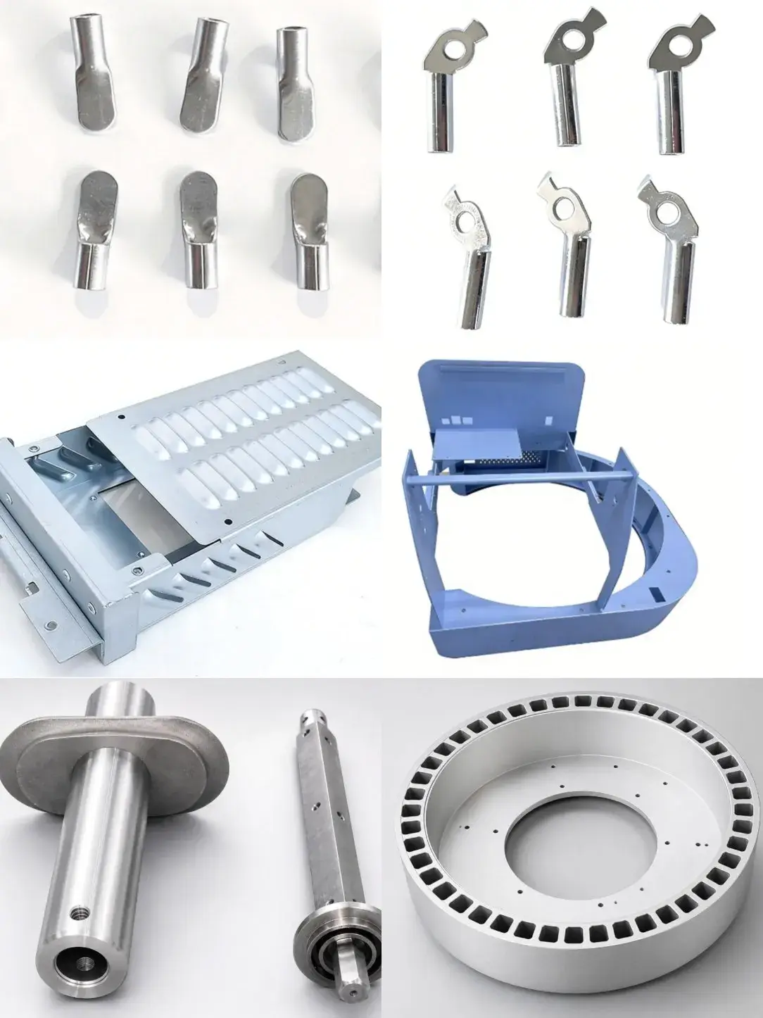
多様なエンジニアリングおよび製造アプリケーションをサポートします。
-
競争力のある価格とDFM
-
24時間365日対応のエンジニアリングサポート
-
短納期、短リードタイム、最低発注数量なし
認証の検証をオンデマンドで提供:ISO 9001:2015|IATF 16949:2016

荘開について
浙江創凱機電科技有限公司は、2003年3月に設立され、登録資本金は1,500万元です。当社は、精密工具の設計・製造、精密金属プレス加工、精密板金加工、精密機械加工、表面塗装、粉体塗装、精密部品の組立を統合したハイテク企業です。現在、従業員数は95名で、高度な精密加工設備と標準化された作業場を有し、総面積は約13,500平方メートルです。当社は、ISO9001、IATF16949、ISO45001、ISO14001のシステム認証を取得しています。

精密プレス加工用金型の設計・製造

プレス加工工場の主なプレス設備:16トン、25トン、40トン、60トン、80トン、110トン、200トン、250トンなどの仕様を持つ高速精密プレス機18台。高速精密プレス機のプレス速度は毎分500回に達する。
プレス加工用材料:真鍮、リン青銅、ベリリウム青銅、ニッケル白銅、各種鋼材、ステンレス鋼材、ニッケルストリップ、冷間圧延鋼板、帯鋼(めっき済みを含む)、亜鉛めっき鋼板、低炭素鋼、ばね鋼、その他の複合材料。
精密板金加工

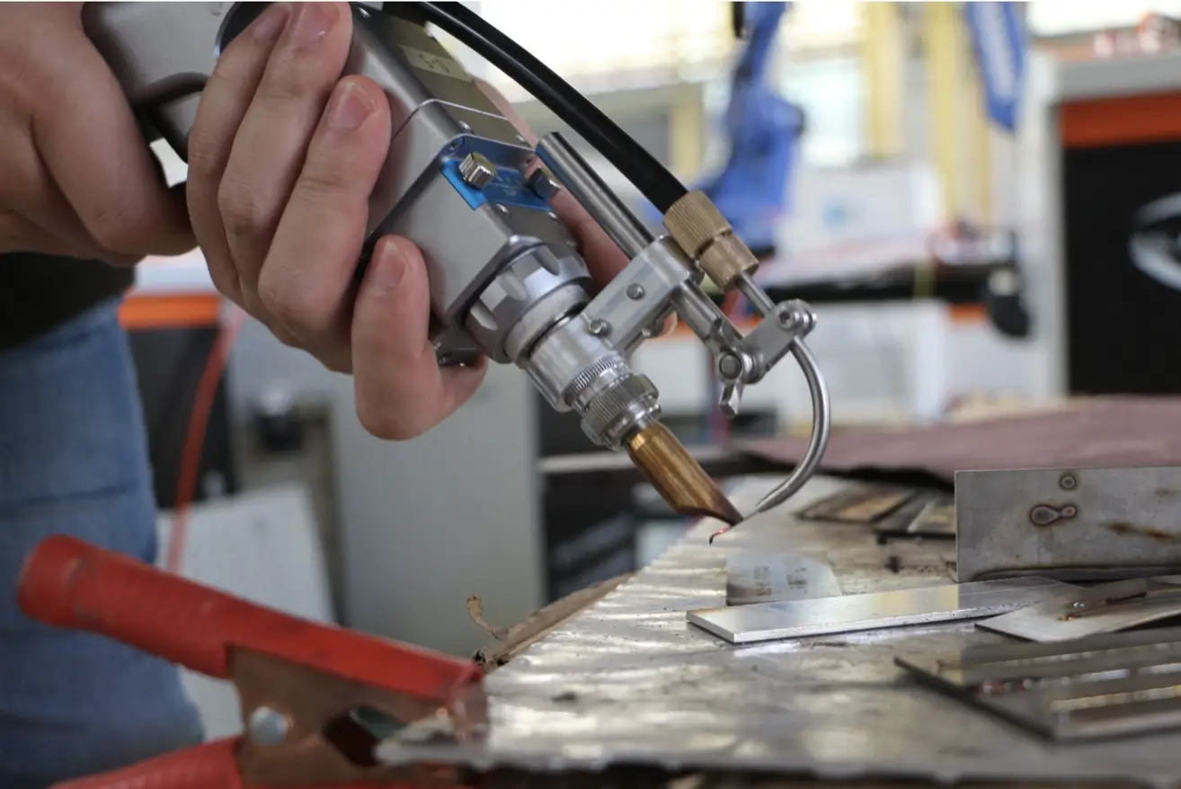
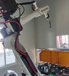
板金加工工場には、2台の大型先進CNCレーザー切断機、1台のCNCパンチプレス、5台のCNC曲げ加工機、リベット打ち機、溶接機、研削盤、伸線機などの精密板金加工設備が備えられています。
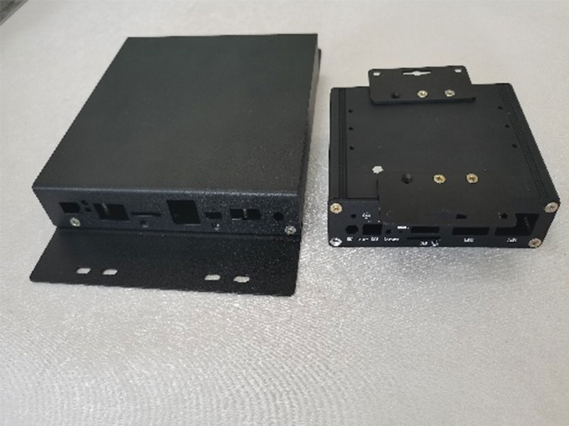
加工対象製品は、産業オートメーション、医療機器、電気機器、電気ボックス、電気接続ボックスなどの分野にわたります。ステンレス鋼、炭素鋼、ケイ素鋼、アルミニウム合金、亜鉛メッキ鋼板、アルミニウム亜鉛メッキ鋼板などの金属材料に対し、高速切断や板金加工などの精密加工が可能です。
粉体塗装
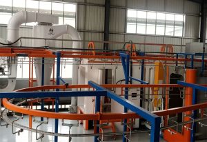
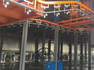
自動粉体塗装ライン1本。
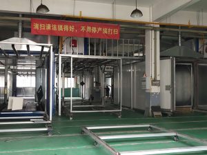
手動粉体塗装ライン1本(大型部品および大型箱用)。
大型部品および大型箱用の手動塗装ライン1本。
自動粉体塗装と塗装を組み合わせたハイブリッドラインが1ライン建設中。
精密機械加工

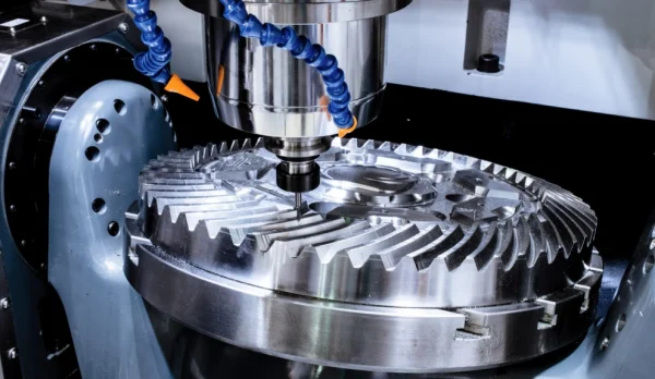
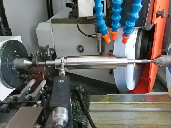
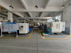
機械加工工場には、4軸CNC工作機械6台、5軸スイス型旋盤1台、精密CNC旋盤13台、CNCフライス盤4台、台湾明陽精密自動旋盤16台、精密普通旋盤、精密3軸デジタル表示フライス盤、精密卓上旋盤、台湾吉傳自動エッジフライス盤、精密ねじ転造盤、ねじ転造ダイス、精密タッピング盤、精密穴あけ盤、台湾精密デジタル表示フライス盤、精密刃物研削盤、内外円筒研削盤、センタレス研削盤、鋸盤、超音波洗浄乾燥機、研磨機、電気溶接機、アーク溶接機などの精密機器が備えられています。
私たちの
イントロビデオ
楽しい豆知識
5社以上のサプライヤーとの調整はもう不要です。コスト効率の高い生産:垂直統合とプロセス最適化により、断片化されたサプライチェーンと比較して15~30%のコスト削減を実現します。
市場投入までのスピード:同時並行エンジニアリングにより、リードタイムを40%短縮。品質を損なうことなく納期を守ります。
無料のDFM分析をご依頼ください:図面やサンプルをアップロードしてください。当社のエンジニアが48時間以内にコストと効率の最適化策を特定します。

会社は
0
登録資本金
0M
スタッフ
0+
工場エリア
0+
私たちのケース
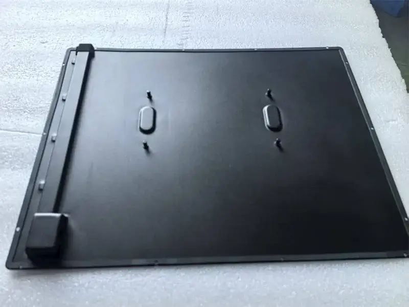
溶接+研磨+削り取りパテ技術の代替として、延伸プロセスを使用する
溶接+研磨の代わりにストレッチングプロセスを使用する +スクレープパテ テクノロジー
技術的なボトルネックを打破し、教育実演装置向けの高品質かつ価格競争力のある金属構造部品を開発する。
ある顧客がトレーニングや教育用の大型デモ用コンピュータを開発していた際、その中核となる金属構造部品に深刻な問題が生じました。当初の設計では、突出部を溶接で形成していましたが、製品テスト段階で溶接部の密着性が低く、重要なテストに合格できませんでした。同時に、溶接工程のコストが高いため、部品価格が競合他社製品よりも大幅に高くなり、納期が迫っていることから、顧客は品質とコストの両面で大きなプレッシャーに直面していました。
問題点を正確に特定し、迅速に対応して解決する。
お客様の窮状を理解した上で、当社は迅速に専門技術チームを編成しました。最初の技術セミナーでは、溶接部の気密性不良の根本原因を徹底的に分析しました。溶接パラメータの最適化と溶接機の導入により、気密性の問題は解決し、お客様の当初の品質要件を満たすことができましたが、溶接コストが高いという問題は依然として残っています。
革新的な計画、2つの柱から構成:
技術チームはそこで止まりませんでした。社内での何度もの議論と顧客との緊密なコミュニケーションを経て、根本的な解決策を提案しました。それは、従来の溶接を一体型のプレス加工と延伸加工に置き換えることです。これにより、溶接不良のリスクを根本から完全に排除できるだけでなく、生産コストを大幅に削減し、製品がより大きな市場シェアを獲得できる可能性も生まれます。
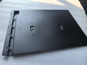
「不可能」を掴み、約束を果たす:
お客様からのフィードバックでは、プレス加工やストレッチ加工の計画が検討されましたが、他のサプライヤーからは実現不可能との指摘がありました。こうした疑問に対し、私たちは「実践を通して学ぶ」という信念を強く持ち、長年にわたる技術蓄積に基づき、以下のような重要な最適化提案をお客様に提供いたします。
引張傾斜角を調整して材料の流動性を最適化し、引張性能に優れた特定のブランドの冷間圧延鋼板を選択する。
優れた結果、顧客から絶賛:
計画が決定した後、複数回の厳格な工程テストとサンプル検証を実施しました。最終的に納品された部品は、お客様の設計要件と性能基準を完全に満たしています。お客様は結果に大変満足され、「これは私の理想とする設計通りの完璧な製品です!」と絶賛されただけでなく、困難な問題を克服するChuangkaiチームの能力にも心から感謝の意を表してくださいました。私たちは、厳しい納期の中で、品質とコストの難題を解決し、お客様の製品が市場競争で優位に立てるよう、お客様を成功裏に支援することができました。
教育用ディスプレイおよびシステム向けに高品質かつ費用対効果の高い金属部品を提供するための技術的課題の克服
課題:
トレーニングや教育用の大型デモ用コンピュータを開発していた顧客は、主要な金属構造部品で重大な問題に直面していました。当初の設計では溶接された突起が使用されていましたが、製品テスト中に溶接部の密閉性が悪く、故障が発生しました。さらに、溶接工程のコストが高いため、部品の価格が競合他社よりも大幅に高くなっていました。プロジェクトの締め切りが迫る中、顧客は品質とコストの両方の課題を解決するために大きなプレッシャーにさらされていました。
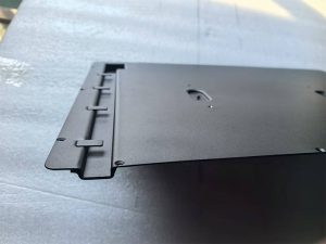
当社の迅速な対応と初期ソリューション:
お客様のジレンマを知った後、当社は直ちに専門の技術タスクフォースを編成しました。最初の技術レビューでは、シール不良の根本原因を徹底的に分析しました。広範な溶接パラメータ最適化試験とロボット溶接の戦略的な導入により、必要なシール完全性を達成し、お客様の品質仕様を満たすことに成功しました。
より深い問題点を特定し、革新的なアイデアを提案する:
差し迫ったシール問題は解決したものの、製造コストが高すぎるという根本的な問題は依然として残っていました。妥協を拒んだ当社のタスクフォースは、集中的な社内ブレインストーミングを行い、クライアントとの緊密なコミュニケーションを維持しました。そして、溶接アセンブリをプレス加工と深絞り加工で成形した一体型部品に置き換えるという革新的な解決策を提案しました。このアプローチにより、以下のメリットが期待できました。
- 溶接に内在するシール不良の根本原因を取り除く。
- 生産工程を効率化することで、大幅なコスト削減を実現します。
- 顧客の最終製品の市場競争力を高めます。
「不可能」を打ち破る:
クライアントは、以前にスタンピングを検討したものの、他のサプライヤーがこの部品には不向きだと判断したと明かしました。「実績こそが証明する」という信念に基づき、当社は技術的な専門知識を活用して重要な設計最適化を提案しました。
- 1. 材料の流れを改善するために、引き抜き角度を調整する。
- 2. 深絞り加工性に優れた、より高グレードの冷間圧延鋼を指定する。
成功事例:
最適化された設計に基づいた厳密なプロトタイピングと検証テストを経て、最終コンポーネントを納品しました。結果は卓越しており、クライアントの設計意図と性能要件に完全に合致していました。クライアントは深い満足感を示し、「これは私が設計で思い描いていた完璧な製品です!」と高く評価しました。彼らは、長年の技術的な悩みを解決してくれたChuangKaiに明確に感謝しました。私たちは、クライアントが重要な納期を守ると同時に、品質上の欠陥とコストの壁の両方を克服し、製品の市場競争力を大幅に向上させることを可能にしました。
農業機械のシャフト破損に対する改善策に関する事例研究
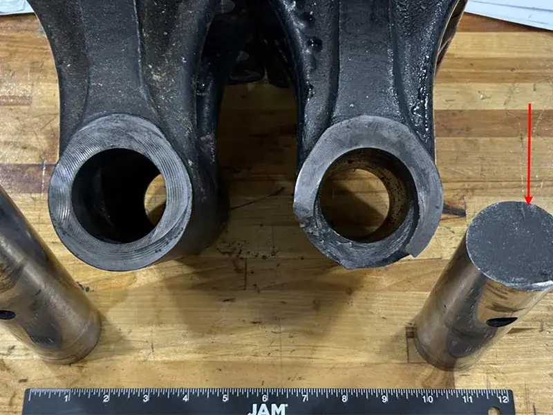
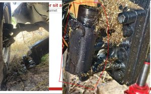
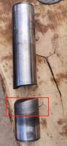
2024年7月、ある顧客から、コンバインハーベスターの軸が圃場作業中に破損したとのフィードバックがあり、エンドユーザーは熟した穀物をスムーズに収穫できないことを非常に心配していました。彼らは当初、軸の原材料である40CrNiMoA、または熱処理工程が要件を満たしていないのではないかと考えていました。弊社は、お客様のご協力により、破損した軸を最初に分析し、原材料や工程に問題があるのではなく、お客様の設計によるものであると結論付けました。季節は、機器の複雑な作業条件を考慮していません。また、一方向の力による疲労の隠れた危険性、お客様の要求事項、全体の高硬度熱処理によりコアの硬度が高くなり、疲労による破損が発生しやすいこと、分析の結果、全体の調整品質プラス表面誘導焼入れ工程を、元の熱処理全体の高硬度工程に置き換え、コアの硬度を下げ、外面の硬度を高くして耐摩耗性を満たすようにすることを提案し、提案された工程に従ってお客様に送付しました。新しいサンプルは、2回目の現場実験で優れた結果を達成しました。実を結び、お客様からのフィードバックを得ました。
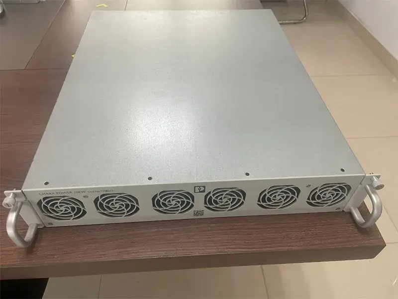
電源ボックス筐体の改善プロセス
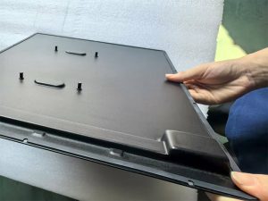
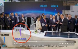
当社のドイツ人顧客が、設計段階で難航している組み合わせボックスを抱えていました。リベット留め方式を採用すると、平面から突出して機能に影響が出てしまいます。溶接方式では、外観が要求を満たさず、コストも高額になります。弊社にご連絡いただいたところ、他のプロジェクトで同様の成功事例があったため、ダブルフラットヘッドリベットとサラダホールを使用することで、お客様の問題をうまく解決できることが分かりました。そこで、サンプルをお客様にお送りしました。
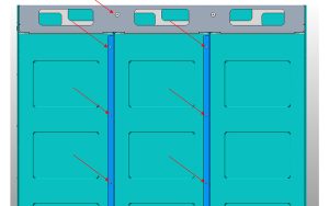
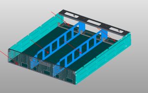
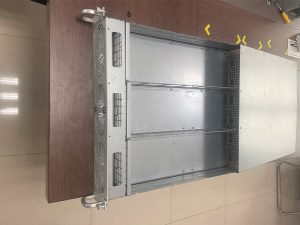
彼らはハノーバー展示会で非常に満足し、素晴らしい成果を上げました。満場一致の称賛を獲得しました!

エンドツーエンドの製造ソリューションパートナー
エンドツーエンドの製造ソリューションパートナー
構想から完成まで – 世界的な成功のための精密設計
ChuangKaiでは、複数のサプライヤーからの調達に伴う複雑さを排除します。ODMおよびOEMソリューションを専門とする垂直統合型メーカーとして、包括的な能力を活かし、高精度部品のシームレスな生産を実現します。
統合製造サービス:
- 機械加工:CNCフライス加工/旋削加工、スイス型旋盤加工
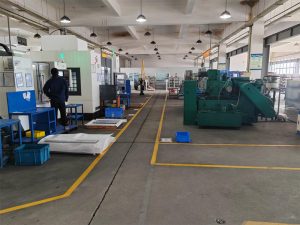
- 金属加工:レーザー切断、曲げ加工、溶接
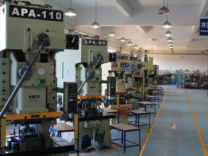
- プレス加工と成形:順送金型プレス加工、深絞り加工
- 金型・成形:カスタム金型設計・製造
- 表面処理:粉体塗装、スプレー塗装
- 組み立てとテスト:フルキット化、品質検証
ODM/OEMが貴社にもたらすメリット:
デザイン革新
当社のエンジニアリングチームは、お客様と協力して、製造性、コスト効率、性能を最適化する設計を行い、コンセプトを市場投入可能な製品へと変革します。
単一情報源による説明責任
5社以上のサプライヤーとの調整はもう不要です。当社がすべてのワークフローをワンストップで管理します。
設計 → 試作 → 金型製作 → 原材料調達 → 生産 → 仕上げ → 組立 → 物流
コスト効率の高い生産
垂直統合+プロセス最適化=断片化されたサプライチェーンと比較して15~30%のコスト削減。
|市場投入までのスピード|
同時並行エンジニアリングにより、リードタイムを40%短縮できます。品質を損なうことなく納期を守ります。
|品質は最初から組み込まれている|
ISO認証取得済みのプロセスとデジタル追跡システム。PPAP、FAIR、CPKレポートに対応。
√ 当社がサービスを提供する業界:
自動車 | 産業機械 | 医療機器 | 再生可能エネルギー | ロボット工学 | 原子力発電
グローバル企業が当社を選ぶ理由:
問題解決者:例えば、[教育デモンストレーション機器の事例]では、溶接されたアセンブリを一体型のプレス加工部品に置き換え、漏れを解消し、コストを25%削減しました。
拡張可能な生産能力:NPIプロトタイプから100万台以上の量産までをサポートします。
技術力:20名以上のエンジニアが、複雑なGD&T、厳しい公差(±0.01mm)、および材料に関する課題に取り組む準備ができています。
→ 無料のDFM分析を依頼する
図面やサンプルをアップロードしてください。当社のエンジニアが48時間以内にコストと効率の最適化策を特定します。
製品

よくある質問
このセクションでは、当社の機械・電気製品、サービス、ポリシーに関するよくある質問にお答えします。サポートに問い合わせることなく、必要な情報を素早く見つけることができます。
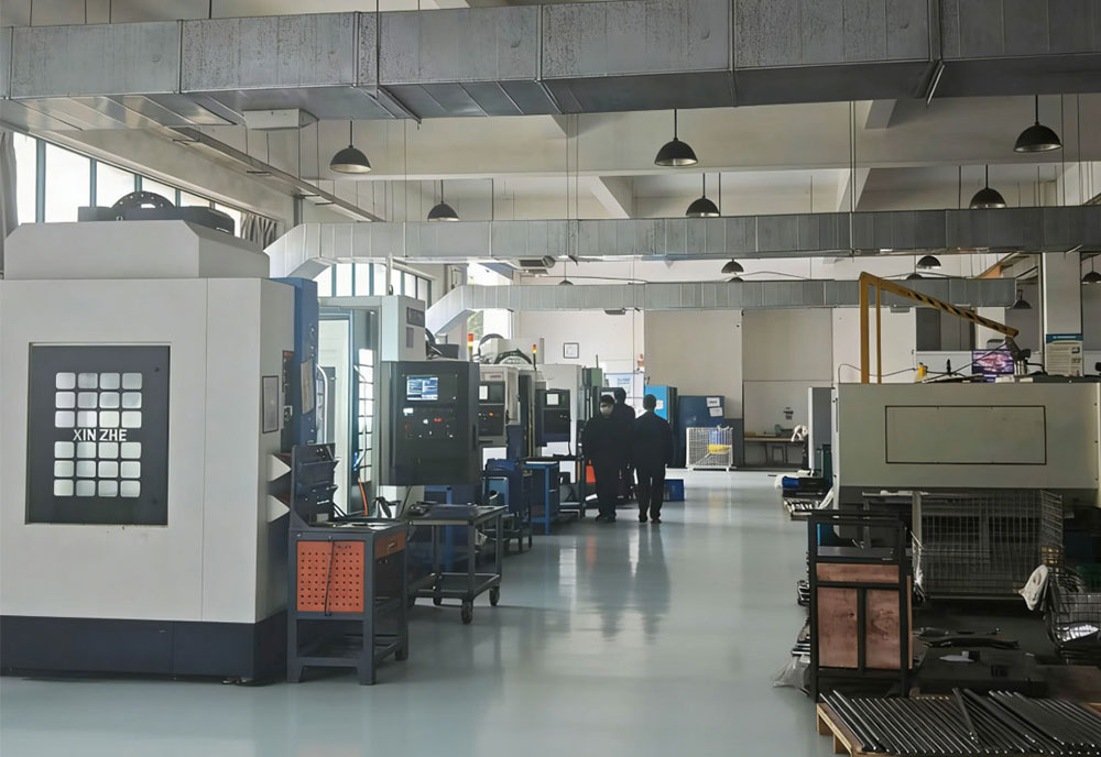
当社の強みは、精密機械加工、精密板金加工、プレス加工、受託設計・製造、スプレー塗装による専門的な表面処理から最終製品の組み立てまで、産業チェーン全体を統合し、全工程にわたって卓越した品質管理システムを導入している点にあります。これにより、お客様は複数のサプライヤーと調整することなく、効率的で一貫性のあるサービスを受けることができます。当社はあらゆる工程で厳格な品質管理を実施し、最終的に納品されるのは要求を満たす部品や製品だけでなく、安定性、信頼性、そして高水準の総合的なソリューションであることを保証することで、お客様の納期短縮、コスト削減、サプライチェーン効率の向上を効果的に支援します。
特注の非標準部品加工。納期は製品の複雑さによって異なります。通常、納期は2~4週間です。
25
経験年数



















お問い合わせ
最近の記事
最近の記事
機械・電気に関するソリューションが必要な場合、またはご質問がある場合は、お気軽にお問い合わせください。
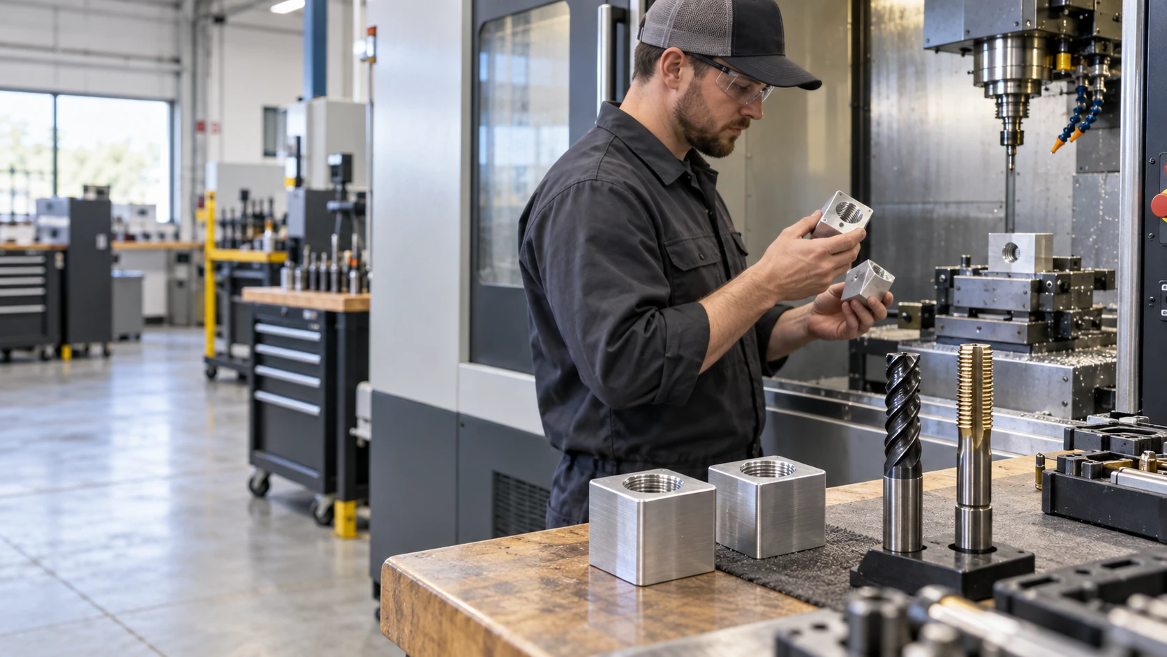
Tapping vs. Thread Milling for CNC-Machined OEM Parts: Choosing the Right Internal Thread Process
23
10月
The choice between tapping and thread milling depends on the hole, material, thread specification, production quantity, machine capability, and cost of failure. Tapping is usually the faster route for repeat production of standard internal threads. Thread milling offers more control over thread size and fit, handles a wider range of diameters with fewer tools, and can reduce the consequence of a tool failure in a valuable part.
Neither process is universally better. A through-hole in a stable aluminum part may favor tapping, while a large thread, difficult material, expensive near-finished component, or close fit adjustment may justify thread milling. Blind-hole geometry and usable thread depth can change the answer again.
Tapping vs Thread Milling at a Glance
| Decision factor | Tapping | Thread milling |
| Cycle time | Often faster for standard repeated threads. | Usually longer because the tool follows a helical path. |
| Tool flexibility | One tap normally matches a specific size, pitch, and form. | One cutter may cover multiple diameters that share a compatible pitch and profile. |
| Fit adjustment | Limited after the tap and hole preparation are selected. | Tool-path offsets can adjust the finished thread within process limits. |
| Failure risk | A broken tap may be difficult to remove from the part. | A smaller cutter may be easier to recover from, but breakage can still damage the feature. |
| Machine need | Requires controlled feed and rotation appropriate to the tapping method. | Requires CNC helical interpolation, suitable control, rigidity, and access. |
How Each Process Cuts an Internal Thread
Both methods begin with a prepared hole, but their tool engagement is different. The drawing must specify the finished thread; the process planner then selects the pre-hole, tool, cutting data, and inspection route.
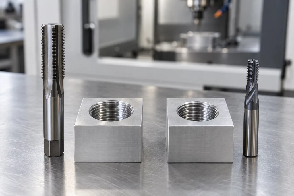
Tapping
A tap advances axially while its cutting edges or forming lobes create the complete thread profile. Because the tool engages around the circumference, torque, alignment, lubrication, chip control, and the prepared-hole diameter are important. Cut taps generate chips. Form taps displace suitable ductile material without chips, but they require a different hole size and should be approved for the material and specification.
Thread Milling
A thread mill rotates while the CNC moves it along a helical path. The cutter is smaller than the finished thread, so it engages a portion of the circumference at a time. The program controls diameter and direction, and suitable cutters can produce internal or external threads. The method needs enough bore access, tool clearance, machine interpolation, and stable workholding.
Choose by Hole Geometry
Through Holes
Through holes usually provide easier chip evacuation and fewer bottom-clearance constraints. For standard sizes and meaningful batch quantities, tapping often provides the most efficient cycle. A spiral-point cutting tap may push chips ahead through the opening when the material and application permit. Thread milling remains useful for large diameters, adjustable fits, mixed thread sizes, or parts where tool-breakage recovery influences the risk calculation.
Blind Holes
Blind holes need separate values for drilled depth, full thread depth, usable engagement, and bottom clearance. A tap has an incomplete lead before it produces full threads, and chips must have somewhere to go. Tap style, coolant delivery, chip evacuation, and reversal therefore matter. Thread milling can approach a shoulder with controlled axial positioning, but it still needs entry and exit clearance and cannot create usable thread beyond its programmed geometry. Do not specify “thread to bottom” without defining a manufacturable termination.
Choose by Material and Thread Specification
Material behavior affects torque, chips, tool wear, heat, and edge quality. Standard threads in machinable aluminum may favor tapping for speed, although chip packing or built-up edge still needs control. Tough stainless steels, high-temperature alloys, or expensive heat-treated parts may make the lower engagement and recovery advantages of thread milling more attractive. The supplier should confirm the exact alloy, hardness, and hole depth before choosing the route.
Thread size and form matter as much as material. Small standard threads may suit tapping, while larger diameters, special profiles, right- and left-hand variants, or adjustable fit classes can favor thread milling. A thread mill is not universal: its diameter, pitch capability, length, cutting form, and reach must match the feature.
Choose by Quantity and Cost of Failure
For a stable high-volume job, the shorter cycle of tapping can outweigh its lower flexibility. For prototypes and mixed families, thread milling may reduce the number of dedicated tools and allow diameter correction through offsets. The value of the workpiece also matters. Breaking a tap in an almost-complete housing can cost more than the saved cycle time; however, thread milling adds programming time and may use a more expensive cutter. Compare total route cost, not tool price alone.
Define the Thread Correctly on the Drawing
A process comparison cannot correct an incomplete specification. Use the same feature-based discipline applied to CNC machining tolerances, and include the following information:
- Thread standard and designation, nominal size, pitch or threads per inch, internal class or tolerance, and right- or left-hand direction.
- Through or blind condition, drilled depth, full thread depth, minimum usable engagement, entrance chamfer, and any bottom-clearance limit.
- Material grade and condition, heat treatment, coating or plating, quantity, critical datum relationships, and mating-fastener information.
- Inspection method, gauge standard, sampling level, first-article record, and any functional assembly test.
A complete CNC machining RFQ checklist also keeps model, drawing, revision, finish, and inspection assumptions consistent across bidders.
Verify the Sample and Production Route
Inspect the pre-hole as well as the finished thread. Confirm location, diameter, depth, chamfer, burr condition, and cleanliness. Use the specified GO and NO-GO gauges or another agreed method, then test the real mating fastener when assembly behavior matters. Record tool offsets and wear limits for thread milling, or torque, tap life, and chip-control checks for tapping. A first article should also confirm that coating, plating, or heat treatment does not invalidate the final fit.
Evaluate Supplier Capability Against the Part
CK Metal Tech publishes precision machining capabilities that include CNC milling, drilling, tapping, and related inspection resources. Its broader CNC machining services for precision metal parts provide the context for OEM process planning. The project review should still confirm whether tapping, thread milling, or another threading method is available and appropriate for the specific size, material, depth, tolerance, quantity, and inspection plan.
結論
Use tapping when a standard internal thread, suitable material, controlled hole, and repeat quantity make cycle time the priority. Consider thread milling when fit adjustment, large or varied sizes, difficult materials, blind-hole constraints, or the cost of a trapped broken tap changes the economics. The drawing and sample plan should make the choice verifiable rather than leaving it to habit.
よくある質問
Is Thread Milling Always More Accurate Than Tapping
No. Either process can make acceptable threads when the machine, tool, hole preparation, setup, and inspection suit the requirement. Thread milling offers useful diameter adjustment, but it does not replace process control.
Which Process Is Better for Blind Holes
It depends on usable depth, bottom clearance, material, chip control, thread size, and quantity. A suitable tap can be efficient; thread milling can improve control where evacuation or failure consequences are difficult.
Can One Thread Mill Cut Several Thread Sizes
Sometimes. A cutter may cover multiple diameters with a compatible pitch and profile, within its diameter and reach limits. Confirm the tool manufacturer’s range and the required thread form.
How Should an Internal Thread Be Inspected
Use the drawing’s specified gauge or measurement method and sampling plan. GO and NO-GO gauges are common, but depth, location, surface condition, and functional assembly may also require verification.
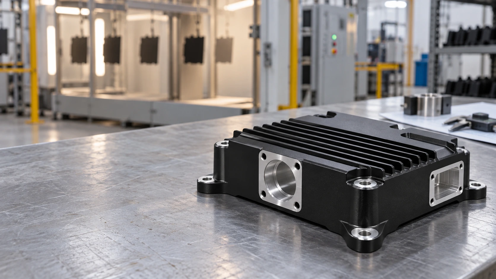
Can CNC-Machined Aluminum Housings Be Powder Coated? Thermal Interfaces, Fits, and Masking
22
10月
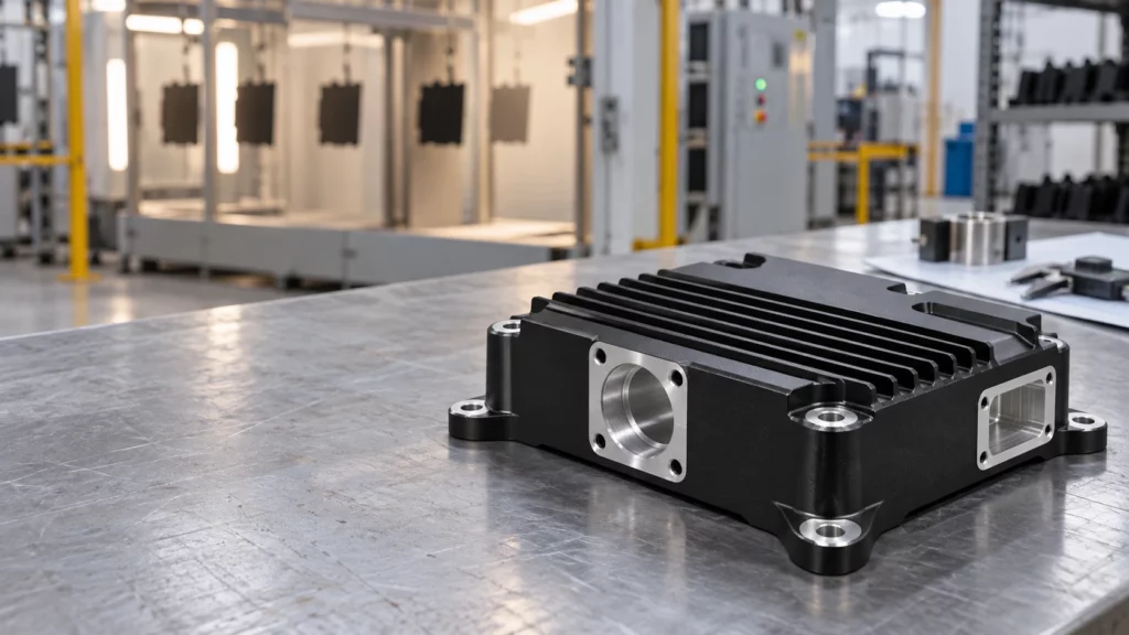
Can aluminum be powder coated after CNC machining? Yes, provided the drawing distinguishes cosmetic or protective surfaces from interfaces that must remain dimensionally, electrically, or thermally functional. A coating that performs well on an exterior wall can cause interference in a close fit, obstruct a thread, insulate a bonding point, or add thermal resistance at a heat-transfer joint.
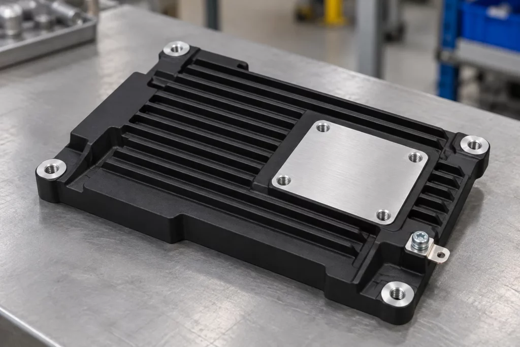
The review should therefore start with the finished assembly, not the color. CK Metal Tech’s aluminum alloy cooling and shielding cover plate illustrates why this distinction matters: one machined component may combine an exterior cover, mounting holes, grooves, structural bosses, shielding functions, and heat-dissipation duties. Those surfaces should not automatically receive the same finish treatment.
Map Functional Surfaces Before Coating
Create a finish map on the controlled drawing or model. Identify coated faces, cosmetic faces, no-coat zones, and surfaces whose final dimensions apply after finishing. A generic note such as “powder coat black” does not tell the manufacturer how the housing must assemble or perform.
Surfaces Commonly Suitable for Coating
Exterior walls, non-mating covers, guards, and handling surfaces are typical candidates when the selected pretreatment and powder system match the aluminum alloy and service environment. Coating can support appearance and surface protection, but corrosion, chemical exposure, ultraviolet exposure, and cleaning requirements still need project-specific confirmation.
Surfaces That Often Need Masking
Common no-coat candidates include bearing or bushing seats, locating datums, close-tolerance bores, sliding rails, O-ring lands, sealing faces, connector grounds, threaded holes, fastener seats, and direct thermal contact pads. The decision is functional rather than categorical: a clearance hole may tolerate film build, while a locating hole with the same nominal diameter may not.
Mask Boundaries Need Their Own Definition
A no-coat note should show where the boundary begins, which direction the mask may shift, and whether a small transition band is acceptable. This is important around countersinks, spotfaces, grooves, stepped bores, gasket lands, and thermal pads. Masking has practical placement variation, and the cured edge may not form a perfectly sharp geometric line. Keep the boundary away from a sealing path or precision datum where possible. If the transition itself affects function, dimension it from a stable feature and include it in the first-article inspection plan.
How Powder Coat Changes Functional Interfaces
Powder coating adds material to the surfaces it covers. The actual build depends on the powder, application, grounding, part geometry, racking, and cure route, so the drawing should define the finished requirement instead of assuming a universal allowance.
| Feature | Coating risk | Drawing or process control |
| Fits and threads | Film build reduces clearance and can obstruct engagement. | Mask, allow for the finish, or approve controlled post-coat machining. |
| Grounding points | The organic film can interrupt metal-to-metal electrical contact. | Mark bonding pads and define continuity or resistance verification. |
| Thermal interfaces | The coating and any trapped air can add resistance at a contact joint. | Keep direct-contact pads bare when required and define flatness, pressure, and interface material. |
| Sealing and datums | Build-up or an uneven mask edge can change seating and measurement references. | State whether dimensions apply before or after coating and locate mask boundaries. |
Fits and Threaded Features
Check each fit against its mating component and the finished-state tolerance. The same feature-level reasoning used for CNC machining tolerances applies after coating. Thread masks must protect the required diameter, lead-in, and usable depth. Forcing a screw through cured powder is not a controlled acceptance method because it can damage the finish and leave debris in the assembly.
Grounding and Thermal Contact
A designated grounding pad needs a clean boundary, a suitable fastener interface, and a defined verification method. Bare aluminum may also need a compatible protection strategy that preserves conductivity. For heat-transfer pads, evaluate coating together with contact area, surface flatness, clamping pressure, and any thermal interface material. A sample should be tested under representative heat load when temperature performance is critical.
Coordinate CNC Machining and Powder Coating as One Route
The safest sequence is established before chips are cut. Treat masking, finishing, and final inspection as part of the manufacturing plan rather than instructions added after machining.
- Review the current drawing, aluminum grade or approved alternative, functional interfaces, cosmetic zones, and operating environment.
- Machine the housing with any agreed allowance for surfaces controlled in the finished state; deburr edges without altering critical geometry.
- Clean and pretreat the part using a route compatible with the alloy, contamination condition, and specified coating system.
- Install plugs, caps, or high-temperature masking at the defined boundaries, then verify mask seating before spraying.
- Apply and cure the coating, remove masks cleanly, and inspect boundaries for lifting, chips, or unintended coverage.
- Complete only approved secondary machining or thread restoration, then clean the part and protect newly exposed aluminum as required.
An integrated review can connect the company’s precision machining capabilities with its powder coating service. The exact masking materials, post-coat operations, and inspection methods should still be confirmed for the part.
Verify the First Article Before Production
A first article should prove more than color and appearance. Use the actual mating components or representative gauges where possible, and record the drawing revision and coating specification used for approval.
- Dimensions: measure critical fits, datums, hole locations, and flatness in the state specified on the drawing.
- Assembly: install fasteners, covers, seals, rails, connectors, and locating features without forcing or finish damage.
- Electrical function: verify required bonding or shielding continuity at the specified contact points.
- Thermal function: check temperature performance under a representative load when the housing forms part of the heat path.
- Finish: inspect coverage, cure evidence, mask edges, handling damage, and cosmetic acceptance against an agreed reference.
Record nonconforming features separately. A part should not pass because its exterior looks uniform when a thread, bonding pad, thermal interface, or locating surface fails its own requirement.
What to Put in the Drawing and RFQ
Submit the 2D drawing and 3D model with material, quantity, coating system or performance requirement, color and texture, finished-state dimensions, no-coat zones, mask depth, thread callouts, grounding locations, thermal pads, inspection records, mating-part information, and sample approval criteria. Separate prototype quantity from expected production volume so the supplier can evaluate masking fixtures and process controls appropriately.
結論
CNC-machined aluminum housings can be powder coated successfully when the finish map protects the part’s working interfaces. The design should preserve required clearance, thread engagement, electrical bonding, and thermal contact, while the process plan should connect machining, pretreatment, masking, coating, and finished-state inspection.
よくある質問
Should Every Threaded Hole Be Masked
No. Masking depends on thread function, fastener fit, engagement depth, and the approved finishing route. The drawing should identify which threads must remain coating-free and how they will be checked.
Can Powder Coat Be Allowed for in a Close Fit
Sometimes, but the designer and manufacturer must agree on the final clearance and whether the controlling dimension applies before or after coating. Do not rely on a generic film allowance.
Should a Thermal Contact Pad Remain Bare
Often it should when direct metal contact is part of the heat path. Confirm the complete joint, including flatness, contact pressure, interface material, corrosion protection, and the required thermal test.
Is Post Coating Machining Acceptable
It may be, if the operation is planned. Control chips, protect the surrounding finish, re-inspect dimensions, and define how newly exposed aluminum will be handled.
Request a Joint Machining and Coating Review
Send CK Metal Tech the drawing revision, alloy, quantity, mating-part details, coating requirements, no-coat zones, thermal duty, grounding needs, and inspection expectations. Use the request a joint machining and coating review route to confirm the manufacturing sequence before quotation.

One Metal Supplier vs Multiple Vendors: How to Calculate Total Landed Cost
16
10月
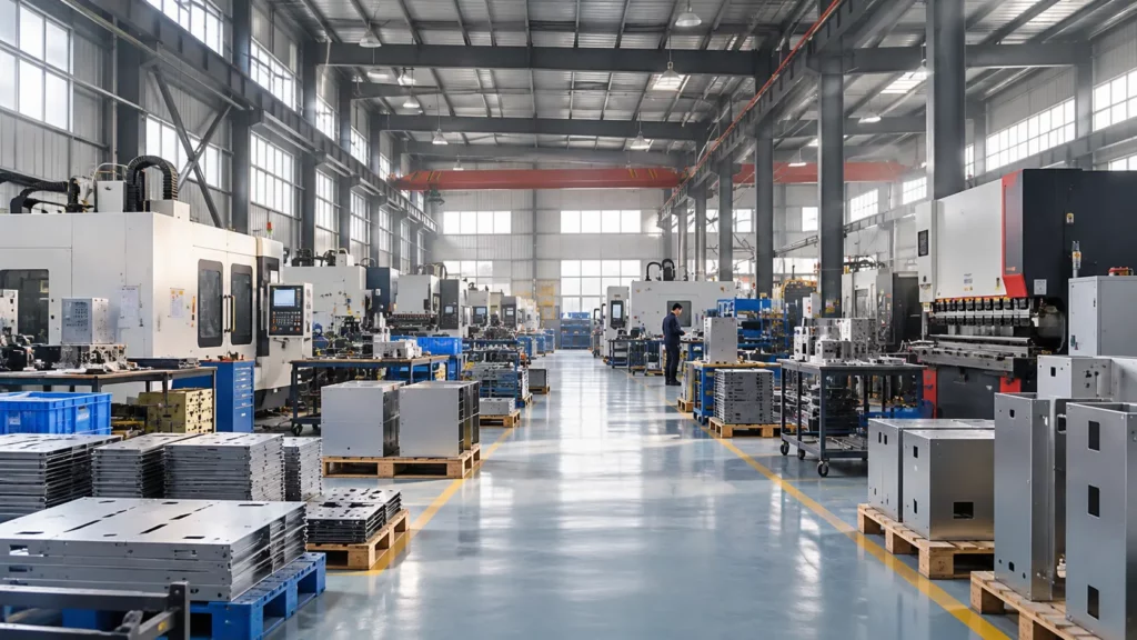
One metal supplier can reduce transfers between fabrication, finishing, and assembly, but supplier consolidation does not automatically lower total landed cost. Compare both routes at the same delivery destination, then add the buyer-side costs needed to turn delivered parts into accepted assemblies. Keep those layers separate: shipping and import charges belong in the landed-cost calculation; supplier administration, inventory, and integration costs belong in the broader sourcing decision.
For an OEM buying custom metal parts, this distinction prevents a lower piece price from hiding extra work. It also avoids calling every future operating expense a landed cost.
Define the Deliverable Before Comparing Vendors
Start with one controlled bill of materials and drawing revision. Specify material, finish, quantity, inspection criteria, packaging, destination, and assembly responsibility. A coated panel from one vendor cannot be compared directly with an assembled enclosure from another unless the missing operations are priced separately.
Distinguish process splitting from dual sourcing. Sending cutting to one shop and coating to another creates sequential handoffs. Qualifying two independent suppliers for the same finished assembly creates a backup route. These arrangements have different costs and continuity benefits; combining them under “multiple vendors” obscures the decision.
Calculate Total Landed Cost in Two Layers
The core shipment calculation is:
Landed cost = supplier invoices + separately charged tooling + packaging + freight + insurance + applicable duties, taxes, and clearance fees.
The International Trade Administration’s landed-cost guidance supports the product-plus-delivery approach. For metal parts, verify which charges are already included in each quotation. Add only costs outside the quoted scope, and use the same receiving location.
Then calculate a separate management metric:
Sourcing comparison cost = landed cost + buyer assembly and inspection + supplier administration + inventory carrying cost + evidence-based quality and disruption allowances.
This second formula is a purchasing decision tool, not a customs valuation or accounting rule. It does not include equipment operating costs over the product’s lifetime. Keep recoverable taxes and other accounting treatments identifiable for finance review rather than treating every cash payment as a permanent expense.
Normalize Quotes and Allocate Shared Charges
Use the same currency, demand period, release size, and named delivery point. Record the delivery term and which party pays each freight leg. A quote that includes shipping can appear expensive beside a factory-gate quote until the missing freight is added.
For international purchases, ask a qualified broker to verify classification, origin, applicable charges, and the relevant shipment date. Do not copy a tariff percentage from another part or last year’s order.
Allocate shared freight across a mixed shipment using a defensible driver, such as chargeable weight or occupied volume. Allocate tooling over the realistically committed program quantity, with tooling ownership shown separately. Show first-order and repeat-order costs independently; an optimistic lifetime volume can conceal a costly launch.
A Worked Example for One Thousand Assemblies
The following figures are hypothetical USD amounts, not CK Metal Tech quotations or tariff estimates. Both routes ultimately provide 1,000 accepted assemblies. The single supplier includes assembly in its invoice; the split route requires more buyer assembly work. Charges already included in supplier invoices are excluded from the other rows.
| Cost category | One supplier | Multiple vendors |
| Supplier invoices | $40,000 | $37,000 |
| Tooling and setup | $3,000 | $2,200 |
| Packaging freight and insurance | $1,800 | $3,300 |
| Illustrative import and clearance charges | $1,500 | $1,500 |
| Core landed cost | $46,300 | $44,000 |
| Buyer assembly and inspection | $800 | $3,300 |
| Supplier administration | $400 | $1,200 |
| Inventory carrying cost | $600 | $1,100 |
| Expected quality and rework allowance | $600 | $1,800 |
| Sourcing comparison total | $48,700 | $51,400 |
| Cost per accepted assembly | $48.70 | $51.40 |
Multiple vendors win the core landed-cost comparison by $2,300. After buyer-side costs are included, one supplier is lower by $2,700. This result follows the stated assumptions; it does not prove that consolidation is generally cheaper.
The decision changes if the split route reduces internal assembly effort, avoids quality losses, or provides a valuable qualified backup. Replace every allowance with program evidence before using this example for an award decision.
Measure Handoffs Without Double Counting
Map the route from cutting and forming through machining, coating, final inspection, and packing. Sheet metal fabrication may involve several linked operations, so track the transfers between them rather than counting suppliers alone.
For each handoff, record transport, protective packaging, receiving inspection, queue time, and revision-control responsibility. Estimate internal work from hours multiplied by an approved labor rate. Distinguish cash savings from staff capacity released: fewer purchase orders do not necessarily reduce payroll.
Estimate inventory carrying cost from average inventory value, the approved annual carrying rate, and the time period. Use historical rework and expedite costs where available. For a new program, show low, expected, and high cases rather than inventing a precise failure probability.
Avoid charging the same loss twice. If rejected units already reduce the accepted-unit denominator, check whether a separate scrap allowance repeats that loss. Likewise, do not add replacement freight when it is already included in a rework estimate.
Choose the Route and Test Its Weak Points
One supplier is attractive when interfaces dominate the program: welded frames must match machined brackets, coating boundaries affect fit, and completed assemblies require a coordinated release. Multiple vendors may be preferable when a process needs specialist qualification, capacity is constrained, or a genuinely independent backup is essential.
A backup is only useful if drawings, tooling access, qualification status, and available capacity make it executable. Two suppliers sharing the same critical subcontractor may still have a common interruption risk. Keep continuity requirements visible beside the cost comparison.
Test the decision against smaller releases, a rejected batch, an engineering change, and an expedited shipment. If the winner changes under a small assumption adjustment, resolve that uncertainty before committing the production route.
Request a Comparable Metal Manufacturing Quote
CK Metal Tech combines sheet metal processing, machining, stamping, powder coating, painting, and precision-component assembly. Review its metal manufacturing and assembly capabilities against the proposed route; process breadth alone does not establish capacity or suitability for a particular program.
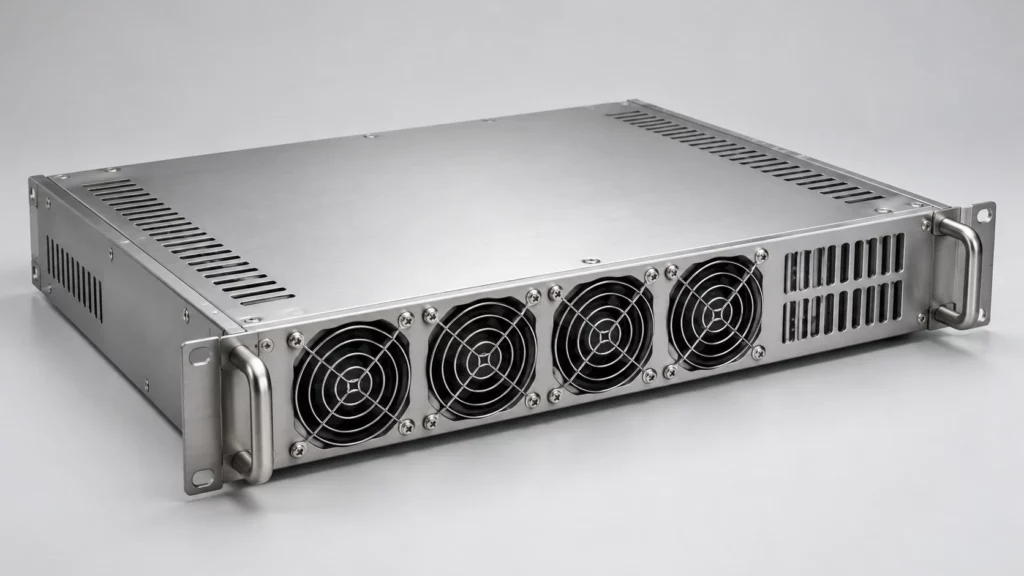
Send the BOM, controlled drawings, quantities, destination, finish requirements, and acceptance plan. Ask CK Metal Tech to separate tooling from recurring prices and identify subcontracted operations, excluded services, and packing assumptions. Give alternative vendors the same package.
結論
Choose the sourcing route using both delivered cost and the work required to obtain accepted assemblies. A transparent comparison can show that multiple vendors win on landed cost while one supplier wins after integration costs, or the reverse. Award the route whose cost assumptions and continuity requirements can be verified.
よくある質問
Is one metal supplier always cheaper
No. Consolidation may reduce transfers and administration, while multiple vendors can provide specialist capability or backup capacity. Compare equivalent outputs and documented costs.
Is total landed cost the same as total cost of ownership
No. Landed cost addresses acquisition and delivery. Ownership cost extends into use, maintenance, and disposal. Buyer integration costs should remain a clearly labeled comparison layer.
How should tooling be included
Show the initial tooling payment separately, then allocate it across a defensible committed quantity for the unit comparison. Record ownership, maintenance responsibility, and repeat-order assumptions.
Should supplier management time count as a saving
Include it when comparing resource demand, but distinguish released staff capacity from actual cash savings. Use measured hours and an approved rate.
Request a Sourcing Route Review
Share the current drawings, BOM, delivery location, release schedule, and assembly scope with CK Metal Tech. Request a sourcing-route review to clarify included operations and compare the assumptions behind each quotation.