







-
Fabricación de prototipos acelerada en 1-3 días y gestión de la cadena de suministro flexible y ágil.
-
Firme compromiso con el envío puntual y la calidad superior constante del producto.
-
Amplia gama de materiales y tratamientos de acabado superficial de estándar industrial.
-
Presupuesto directo de fábrica y desglose de costes totalmente abierto y transparente.
-
Sistema de calidad certificado según las normas ISO 9001:2015 / IATF 16949:2016
-
Servicio de montaje integral llave en mano: Suministramos productos terminados completos y listos para usar, así como piezas de repuesto individuales.
Servicio integral de metalurgia a medida, desde el prototipado hasta la producción en masa.
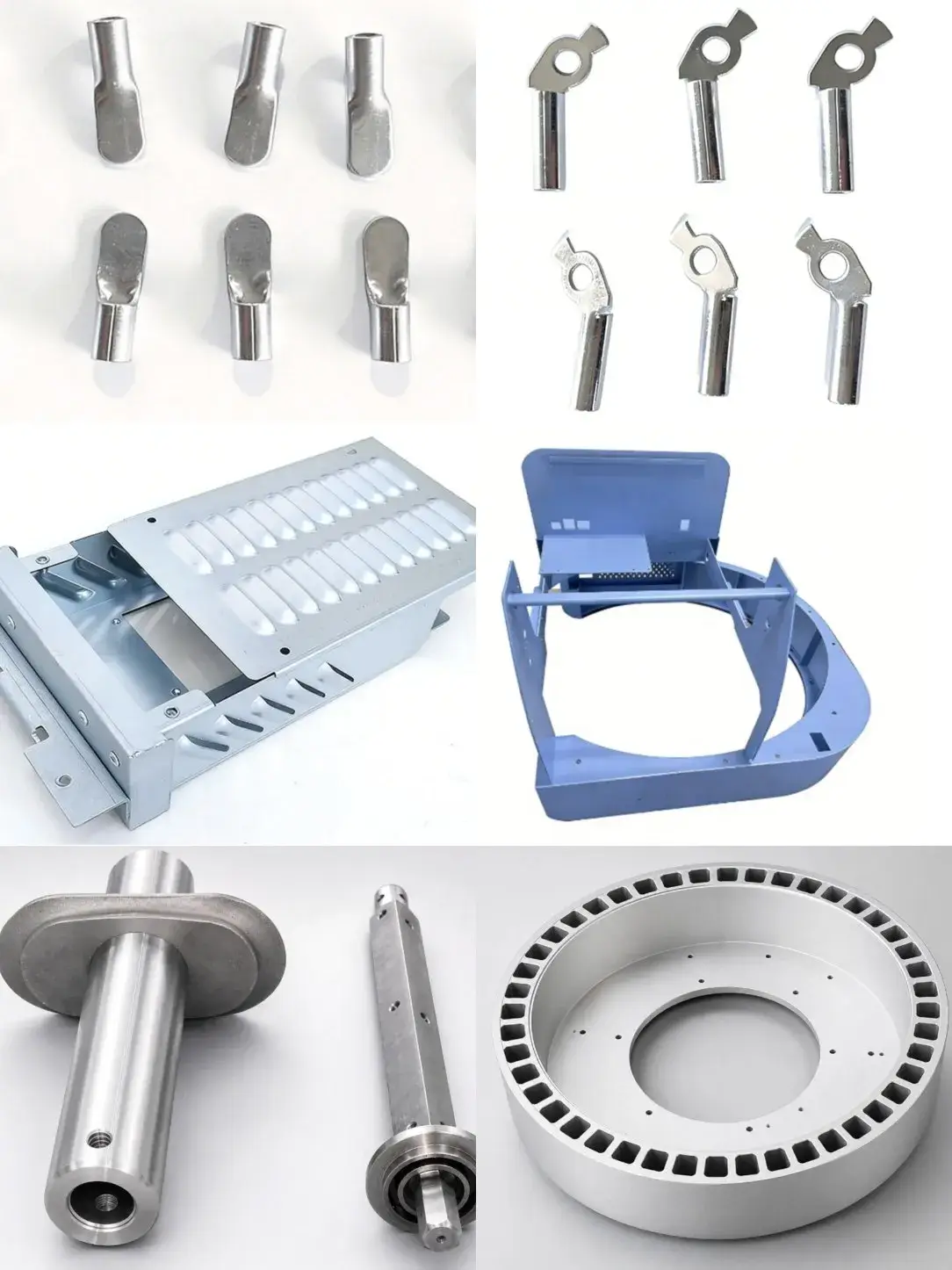
Brindar soporte a diversas aplicaciones de ingeniería y fabricación.
-
Precios competitivos y DFM
-
Soporte de ingeniería 24/7
-
Entrega rápida, plazos de entrega cortos, sin cantidad mínima de pedido.
Verificación de certificaciones bajo demanda: ISO 9001:2015 | IATF 16949:2016

sobre Chuangkai
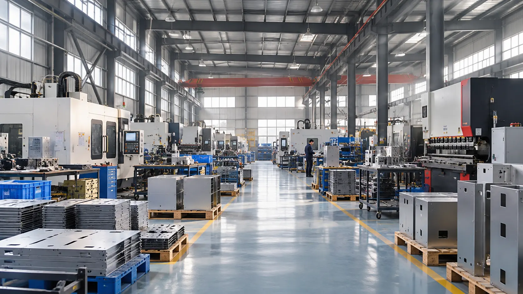
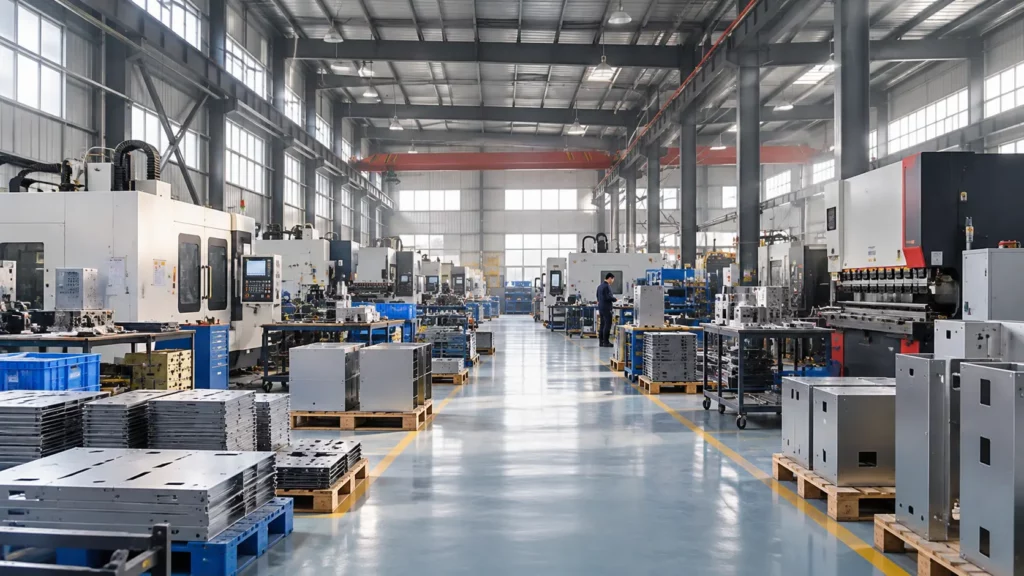
Zhejiang Chuangkai Mechanical and Electrical Technology Co., Ltd. se fundó en marzo de 2003 con un capital social de 15 millones de RMB. La empresa es una compañía de alta tecnología que integra el diseño y la fabricación de herramientas de precisión, estampado de metales de precisión, procesamiento de chapa metálica de precisión, mecanizado de precisión, pintura de superficies, recubrimiento en polvo y ensamblaje de componentes de precisión. Actualmente, cuenta con 95 empleados y posee equipos de procesamiento de precisión avanzados y talleres estandarizados, con una superficie total aproximada de 13 500 metros cuadrados. Hemos obtenido las certificaciones de sistemas ISO9001, IATF16949, ISO45001 e ISO14001.

Diseño y fabricación de herramientas de estampado de precisión

Equipo principal de estampado en el taller: 18 juegos de punzonadoras de precisión de alta velocidad con especificaciones tales como 16 toneladas, 25 toneladas, 40 toneladas, 60 toneladas, 80 toneladas, 110 toneladas, 200 toneladas y 250 toneladas. La velocidad de la punzonadora de precisión de alta velocidad puede alcanzar las 500 veces por minuto.
Materiales para el proceso de estampado: latón, bronce fosforoso, bronce de berilio, cobre blanco de níquel, así como diversos tipos de acero y acero inoxidable, tiras de níquel, acero laminado en frío, acero en fleje (incluido el prechapado), chapas galvanizadas, acero con bajo contenido de carbono, acero para muelles y otros materiales compuestos.
Fabricación de chapa metálica de precisión
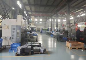
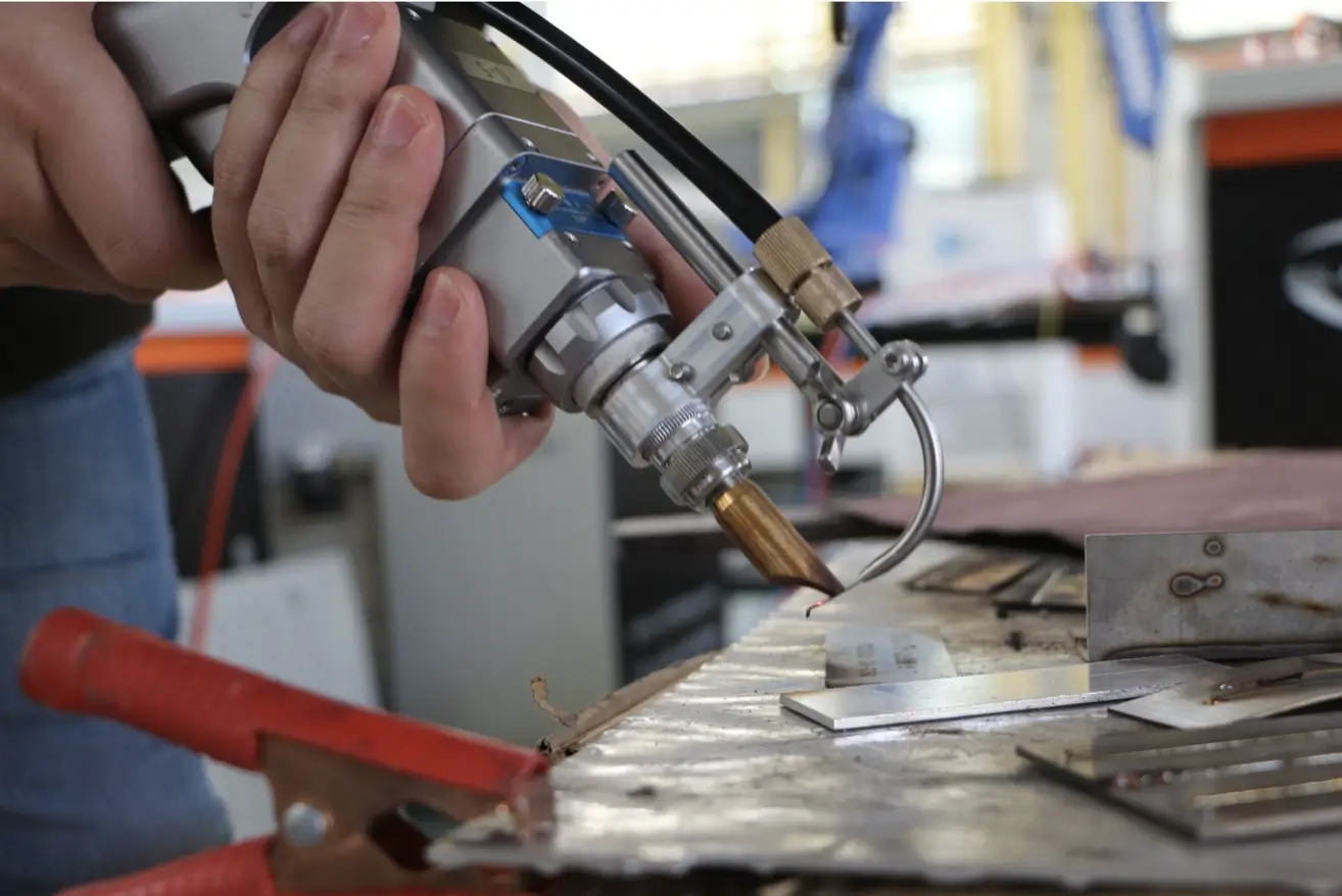
El taller de chapa metálica está equipado con maquinaria de precisión para el procesamiento de chapa metálica, incluyendo 2 máquinas de corte láser CNC avanzadas de gran tamaño, 1 punzonadora CNC, 5 dobladoras CNC, así como remachadoras, máquinas de soldar, amoladoras, trefiladoras y otros equipos.
Los productos procesados abarcan automatización industrial, equipos médicos, equipos eléctricos, cajas eléctricas, cajas de conexiones eléctricas y otros campos. Permite realizar procesos de precisión, como corte rápido y mecanizado de chapa metálica, en los siguientes materiales: acero inoxidable, acero al carbono, acero al silicio, aleación de aluminio, chapa galvanizada, chapa de aluminio-zinc, etc.
Recubrimiento en polvo y pintura
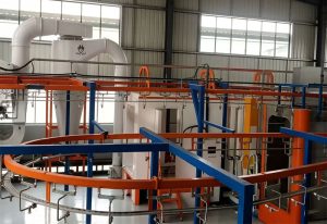
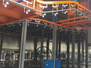
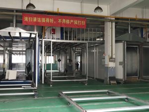
Una línea automática de recubrimiento en polvo;
Una línea de recubrimiento en polvo manual (para piezas grandes y cajas grandes);
Una línea de pintura manual (para piezas grandes y cajas grandes);
Se está construyendo una línea híbrida automática de recubrimiento y pintura en polvo.
Mecanizado de precisión

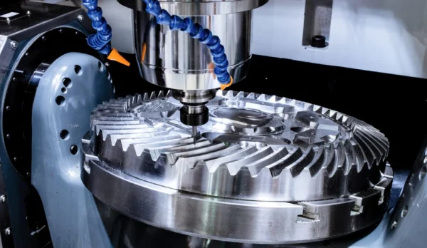
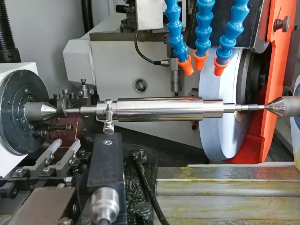
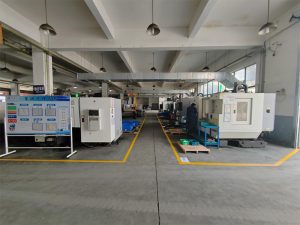
El taller de mecanizado está equipado con maquinaria de precisión, que incluye 6 máquinas CNC de 4 ejes, 1 torno suizo de 5 ejes, 13 tornos CNC de precisión, 4 fresadoras CNC, 16 tornos automáticos de precisión Taiwan Mingyang, así como tornos ordinarios de precisión, fresadoras digitales de precisión de 3 ejes, tornos de banco de precisión, fresadoras automáticas de cantos Taiwan Jizuan, máquinas de laminado de roscas de precisión, matrices de laminado de roscas, máquinas de roscado de precisión, máquinas de taladrado de precisión, fresadoras digitales de precisión Taiwan, rectificadoras de cuchillas de precisión, rectificadoras cilíndricas internas y externas, rectificadoras sin centros, sierras, máquinas de limpieza y secado ultrasónico, pulidoras, soldadoras eléctricas, soldadoras de arco y otros equipos.
nuestro
Vídeo de introducción
nuestros datos curiosos
Se acabó la necesidad de coordinar a más de 5 proveedores. Producción inteligente y rentable: la integración vertical y la optimización de procesos generan una reducción de costes del 15 al 30 % en comparación con las cadenas de suministro fragmentadas.
Rapidez en la comercialización: La ingeniería concurrente reduce los plazos de entrega en un 40 %. Cumpla con los plazos sin comprometer la calidad.
Solicite un análisis DFM gratuito: suba sus planos/muestras. Nuestros ingenieros identificarán optimizaciones de costos y eficiencia en un plazo de 48 horas.

La empresa está construida
0
capital registrado
0METRO
personal
0+
zona de fábrica
0+
nuestro caso
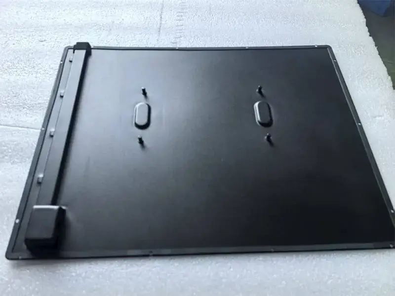
Utilizar el proceso de estiramiento como sustituto de la tecnología de soldadura, pulido y raspado de masilla.
Utilizar el proceso de estiramiento como sustituto de la soldadura y el pulido. +Raspar masilla Tecnología
Superar los obstáculos técnicos y crear piezas estructurales metálicas de alta calidad y precio competitivo para equipos de demostración didáctica:
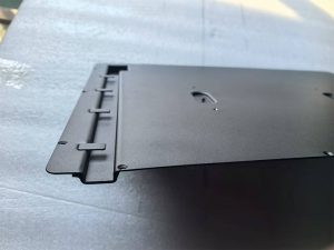
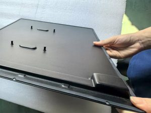
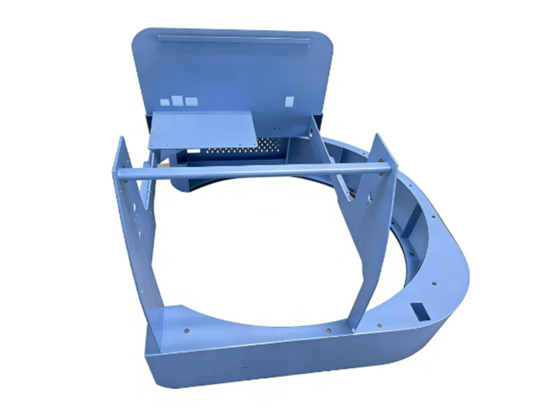
Cuando un cliente desarrollaba una computadora de demostración de gran tamaño para capacitación y enseñanza, sus componentes estructurales metálicos principales presentaron serios problemas. El diseño inicial de la pieza utilizaba un proceso de soldadura para la parte sobresaliente, pero durante la etapa de prueba del producto, la mala estanqueidad de la soldadura impidió que el producto superara la prueba clave. Al mismo tiempo, el alto costo del proceso de soldadura encarecía significativamente el precio de las piezas en comparación con el de la competencia, la entrega del proyecto era inminente y los clientes se enfrentaban a una gran presión en cuanto a calidad y costo.
Localizar con precisión los puntos débiles y responder con rapidez para solucionarlos:
Tras comprender la difícil situación del cliente, rápidamente creamos un equipo técnico especializado. En el primer seminario técnico, analizamos en profundidad la causa raíz de la deficiente estanqueidad de la soldadura. Si bien, mediante la optimización de los parámetros de soldadura y la introducción de máquinas de soldar, hemos resuelto con éxito el problema de la estanqueidad y cumplido con los requisitos de calidad iniciales del cliente, el problema del alto costo de la soldadura persiste.
Plan innovador, de dos fases:
El equipo técnico no se detuvo ahí. Tras numerosas rondas de debate interno y una comunicación fluida con los clientes, propusimos una solución fundamental: sustituir la soldadura original por un proceso integrado de estampado y estirado. Esto no solo elimina por completo el riesgo de soldaduras defectuosas desde el origen, sino que también reduce significativamente el coste de producción y permite que el producto acceda a un mayor mercado.
Aprovecha lo imposible, cumple la promesa:
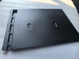
Los comentarios de los clientes consideraron el estampado. El plan se extendió, pero otros proveedores dijeron que no se podía realizar. Ante las dudas, creemos firmemente que "se aprende haciendo". Basándonos en la profunda acumulación de tecnología, brindamos a los clientes sugerencias clave de optimización, que incluyen:
Ajuste el ángulo de inclinación de la tensión para optimizar la fluidez del material y elija una marca específica de chapa de acero laminada en frío con mejor rendimiento a la tracción.
Excelentes resultados, elogiados por los clientes:
Una vez definido el plan, realizamos varias rondas de rigurosas pruebas de proceso y verificación de muestras. Las piezas entregadas finalmente cumplieron a la perfección con los requisitos de diseño y los estándares de rendimiento del cliente. El cliente quedó sumamente satisfecho con los resultados y no solo los elogió efusivamente: «¡Este es el producto perfecto para mi diseño ideal!», sino que también expresó su sincero agradecimiento por la capacidad del equipo de Chuangkai para superar los problemas más difíciles. Hemos ayudado con éxito a nuestros clientes a cumplir con plazos de entrega urgentes, resolviendo problemas complejos de calidad y costes, y contribuyendo a que sus productos obtengan una ventaja competitiva en el mercado.
Superación de obstáculos técnicos para ofrecer componentes metálicos de alta calidad y rentables para sistemas de exhibición educativos.
El desafío:
Un cliente que desarrollaba grandes computadoras de demostración para capacitación y educación se enfrentó a problemas críticos con un componente estructural metálico clave. El diseño inicial utilizaba protuberancias soldadas. Sin embargo, durante las pruebas del producto, la mala integridad del sellado de la soldadura provocó fallas. Para colmo, el alto costo del proceso de soldadura hizo que su componente fuera significativamente más caro que el de la competencia. Con los plazos del proyecto acercándose, el cliente se encontraba bajo una enorme presión para resolver los problemas de calidad y costo.
Nuestra respuesta rápida y solución inicial:
Al conocer el problema del cliente, formamos de inmediato un equipo técnico especializado. En la revisión técnica inicial, analizamos exhaustivamente la causa raíz de la falla del sellado. Mediante extensas pruebas de optimización de parámetros de soldadura y la implementación estratégica de soldadura robótica, logramos la integridad de sellado requerida, cumpliendo con las especificaciones de calidad del cliente.
Identificar el problema de fondo y proponer innovaciones:
Si bien se resolvió el problema inmediato del sellado, persistía el problema fundamental de los costos de fabricación prohibitivos. Negándonos a conformarnos, nuestro equipo de trabajo llevó a cabo una intensa lluvia de ideas interna y mantuvo una comunicación fluida con el cliente. Propusimos una solución transformadora: reemplazar el conjunto soldado con un componente de una sola pieza formado mediante estampado y embutición profunda. Este enfoque prometía:
- Eliminar la causa principal de las fallas de sellado inherentes a la soldadura.
- Logre una reducción significativa de costos mediante la optimización de la producción.
- Mejorar la competitividad en el mercado** para el producto final del cliente.
Superando lo "imposible":
El cliente reveló que previamente había explorado el estampado, pero otros proveedores lo consideraron inviable para esta pieza. Guiados por nuestra creencia de que "la prueba está en la práctica", aprovechamos nuestra experiencia técnica para proponer optimizaciones de diseño cruciales:
- 1. Ajustar el ángulo de estirado para mejorar el flujo del material.
- 2. Especificar un acero laminado en frío de mayor calidad con propiedades superiores de embutición profunda.
El resultado exitoso:
Tras un riguroso proceso de creación de prototipos y pruebas de validación basadas en nuestro diseño optimizado, entregamos el componente final. Los resultados fueron excepcionales, alineándose perfectamente con la intención de diseño y los requisitos de rendimiento del cliente. El cliente expresó su profunda satisfacción y ofreció grandes elogios: «¡Este es el producto perfecto que imaginé en mi diseño!». Agradecieron explícitamente a ChuangKai por resolver su persistente problema técnico. Permitimos al cliente cumplir con su plazo crítico, superando simultáneamente el defecto de calidad y la barrera del costo, lo que mejoró significativamente la competitividad de sus productos en el mercado.
Estudio de caso sobre mejoras para la rotura de ejes en maquinaria agrícola
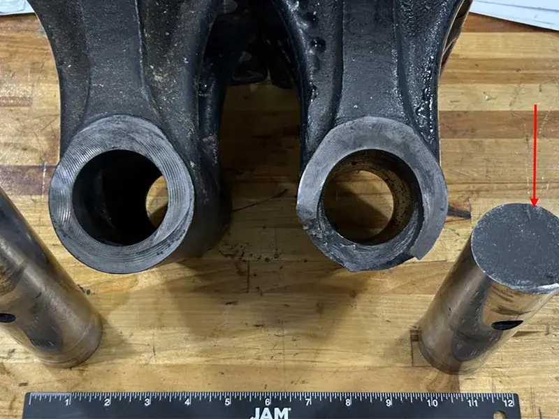
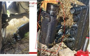
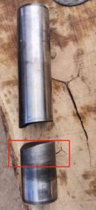
En julio de 2024, un cliente informó que el eje de su cosechadora se había roto durante la operación en el campo, y los clientes finales estaban muy preocupados porque no se podía cosechar el grano maduro sin problemas. Inicialmente pensaron que podría deberse a que la materia prima del eje, 40CrNiMoA, o al proceso de tratamiento térmico no cumplía con los requisitos. Hemos recibido Su ayuda el eje roto fue analizado en el primer momento, y se concluyó que no eran materias primas y Hay un problema con el proceso, pero está diseñado por el cliente. Temporada No se tienen en cuenta las complejas condiciones de trabajo del equipo. Y fatiga de fuerza unidireccional Peligros ocultos, requisitos del cliente Tratamiento térmico de grado duro alto completo conduce a la alta dureza del núcleo, que es fácil de producir rotura por cansancio, Después del análisis Sugerimos adoptar Ajuste de calidad más superficie El proceso de temple por inducción reemplaza el tratamiento térmico original Alta dureza general El proceso hace que la dureza del núcleo Reduzca y la dureza de la superficie exterior es alta, que cumple con la resistencia al desgaste, y se lo enviamos al cliente de acuerdo con el proceso sugerido. La nueva muestra logró excelencia en el segundo experimento de campo. Dar fruto La retroalimentación de.
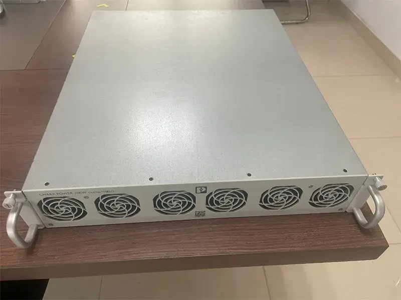
Proceso de mejora de la carcasa de la caja de la fuente de alimentación
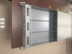
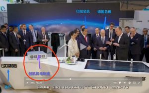
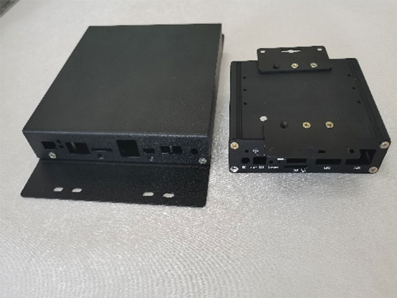
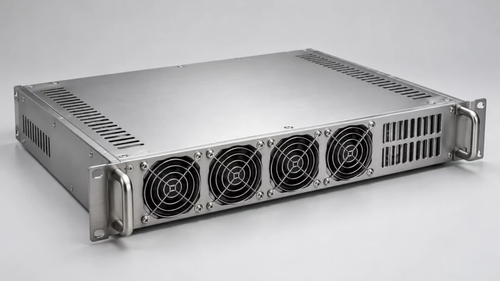
Un cliente alemán de nuestra empresa tiene una caja de combinación con dificultades en la fase de diseño. Si se utiliza el método de remachado, sobresaldrá del plano y afectará a la funcionalidad. Si se utiliza el método de soldadura, el aspecto no cumple con los requisitos y el coste es elevado. Tras contactarnos, descubrimos que habíamos tenido casos de éxito en otros proyectos. Podemos resolver los problemas del cliente de forma muy eficaz utilizando remaches de cabeza plana doble y orificios de ventilación. Enviamos muestras al cliente.
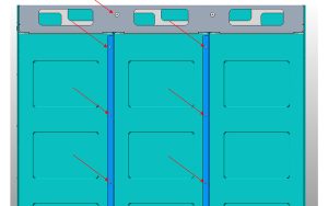
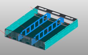
Quedaron muy satisfechos y obtuvieron excelentes resultados en la exposición de Hannover. ¡Recibieron elogios unánimes!

Su socio para soluciones de fabricación integrales
Su socio para soluciones de fabricación integrales
Desde el concepto hasta la finalización: ingeniería de precisión para el éxito global.
En ChuangKai, eliminamos las complejidades del abastecimiento con múltiples proveedores. Como fabricante integrado verticalmente especializado en soluciones ODM y OEM, ofrecemos una producción impecable de componentes de alta precisión gracias a nuestras capacidades integrales:
Servicios de fabricación integrados:
- Mecanizado: Fresado/Torneado CNC, Mecanizado suizo
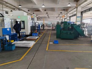
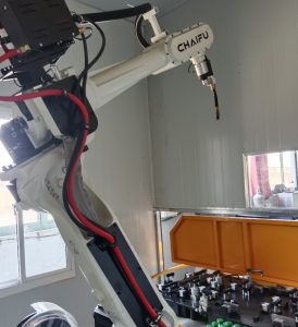
- Fabricación de metales: corte láser, doblado, soldadura.
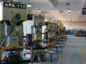
- Estampado y conformado: Estampado con troquel progresivo, embutición profunda
- Herramientas y moldeo: Diseño y fabricación de matrices/moldes a medida
- Tratamiento de superficie: Recubrimiento en polvo, pintura en aerosol
- Ensamblaje y pruebas: Kit completo, validación de calidad.
Ventajas de ODM/OEM para su negocio:
Innovación en el diseño
Nuestro equipo de ingeniería colabora con usted para optimizar los diseños en cuanto a facilidad de fabricación, rentabilidad y rendimiento, transformando los conceptos en productos listos para el mercado.
Responsabilidad de fuente única
Se acabó la necesidad de coordinar a más de 5 proveedores. Gestionamos todo el flujo de trabajo bajo un mismo techo:
Diseño → Prototipado → Herramientas → Abastecimiento de materia prima → Producción → Acabado → Ensamblaje → Logística
Producción rentable
Integración vertical + optimización de procesos = reducción de costes del 15-30% frente a cadenas de suministro fragmentadas.
| Rapidez de comercialización |
La ingeniería concurrente reduce los plazos de entrega en un 40 %. Cumpla con los plazos sin comprometer la calidad.
| Calidad integrada |
Procesos con certificación ISO y trazabilidad digital. Disponibilidad de informes PPAP, FAIR y CPK.
√ Sectores a los que prestamos servicio:
Automoción | Maquinaria industrial | Dispositivos médicos | Energías renovables | Robótica | Generación de electricidad nuclear
¿Por qué nos eligen los clientes internacionales?
Soluciones a problemas: Como en el caso del [Equipo de demostración para la enseñanza] donde reemplazamos conjuntos soldados con piezas estampadas integradas, solucionando fugas y reduciendo costos en un 25 %.
Capacidad escalable: Soporte desde prototipos NPI hasta series de producción de más de 1 millón de unidades.
Agilidad técnica: Más de 20 ingenieros preparados para afrontar desafíos complejos de GD&T, tolerancias estrictas (±0,01 mm) y materiales.
→ Solicitar un análisis DFM gratuito
Suba sus planos/muestras. Nuestros ingenieros identificarán optimizaciones de costos y eficiencia en un plazo de 48 horas.
Productos
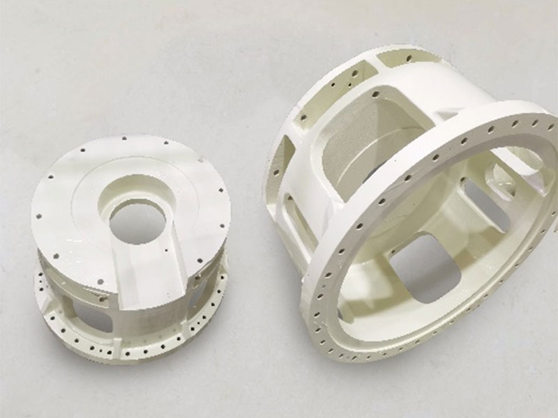

Preguntas frecuentes
Esta sección responde a las preguntas más frecuentes sobre nuestros productos, servicios y políticas mecánicas y eléctricas. Le ayuda a encontrar información rápidamente sin necesidad de contactar con el servicio de asistencia.
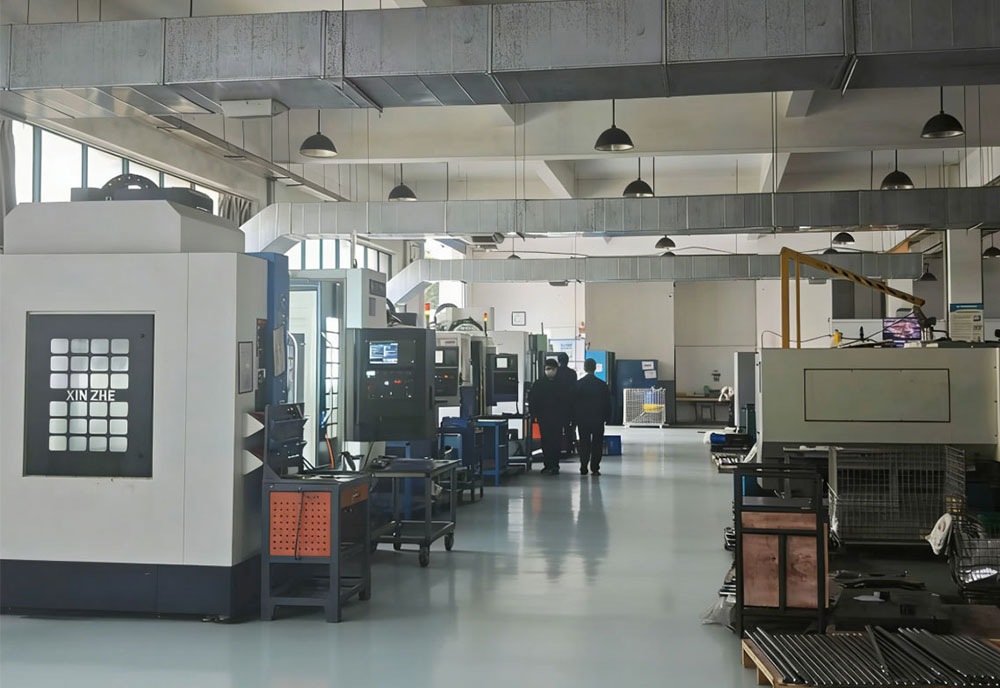
Nuestra principal fortaleza reside en la integración de toda la cadena industrial, desde el mecanizado de precisión, el procesamiento de chapa metálica de precisión, la producción de estampado, el diseño y la fabricación por encargo, el tratamiento superficial profesional mediante pulverización hasta el ensamblaje final del producto, e implementando un sistema de gestión de calidad excepcional en todo el proceso. Esto significa que los clientes no necesitan coordinar a múltiples proveedores para obtener servicios eficientes, coordinados y consistentes. Nuestro estricto control de calidad se aplica en cada eslabón, garantizando que lo que se entrega no solo sean piezas o productos que cumplan con los requisitos, sino también soluciones integrales estables, fiables y de alto nivel, lo que ayuda eficazmente a los clientes a acortar los plazos de entrega, reducir costes y mejorar la eficiencia de la cadena de suministro.
Procesamiento de componentes personalizados no estándar. El costo depende de la complejidad del producto. El plazo de entrega habitual es de entre 2 y 4 semanas.
25
Años de experiencia



















Contáctanos
artículos recientes
artículos recientes
¿Necesitas soluciones mecánicas y eléctricas o tienes alguna pregunta? ¡Contáctanos!
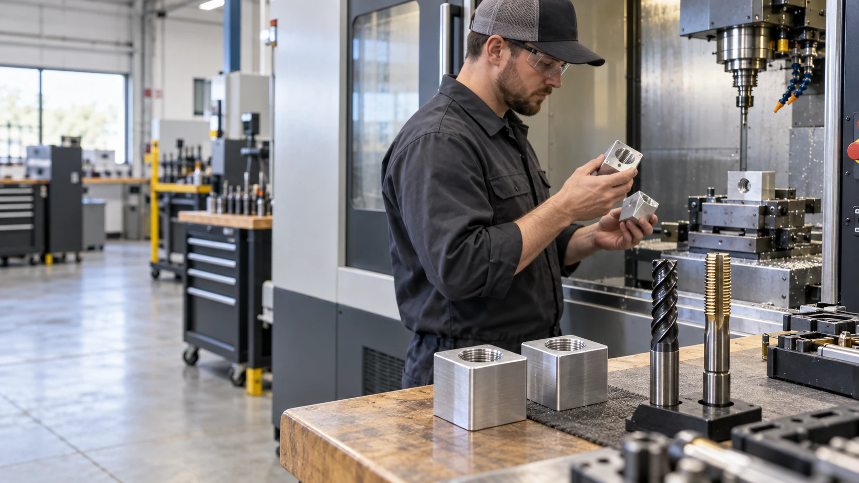
Tapping vs. Thread Milling for CNC-Machined OEM Parts: Choosing the Right Internal Thread Process
23
octubre
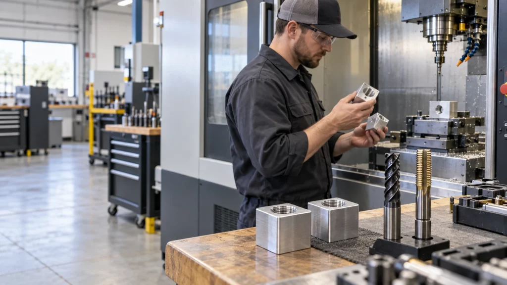
The choice between tapping and thread milling depends on the hole, material, thread specification, production quantity, machine capability, and cost of failure. Tapping is usually the faster route for repeat production of standard internal threads. Thread milling offers more control over thread size and fit, handles a wider range of diameters with fewer tools, and can reduce the consequence of a tool failure in a valuable part.
Neither process is universally better. A through-hole in a stable aluminum part may favor tapping, while a large thread, difficult material, expensive near-finished component, or close fit adjustment may justify thread milling. Blind-hole geometry and usable thread depth can change the answer again.
Tapping vs Thread Milling at a Glance
| Decision factor | Tapping | Thread milling |
| Cycle time | Often faster for standard repeated threads. | Usually longer because the tool follows a helical path. |
| Tool flexibility | One tap normally matches a specific size, pitch, and form. | One cutter may cover multiple diameters that share a compatible pitch and profile. |
| Fit adjustment | Limited after the tap and hole preparation are selected. | Tool-path offsets can adjust the finished thread within process limits. |
| Failure risk | A broken tap may be difficult to remove from the part. | A smaller cutter may be easier to recover from, but breakage can still damage the feature. |
| Machine need | Requires controlled feed and rotation appropriate to the tapping method. | Requires CNC helical interpolation, suitable control, rigidity, and access. |
How Each Process Cuts an Internal Thread
Both methods begin with a prepared hole, but their tool engagement is different. The drawing must specify the finished thread; the process planner then selects the pre-hole, tool, cutting data, and inspection route.
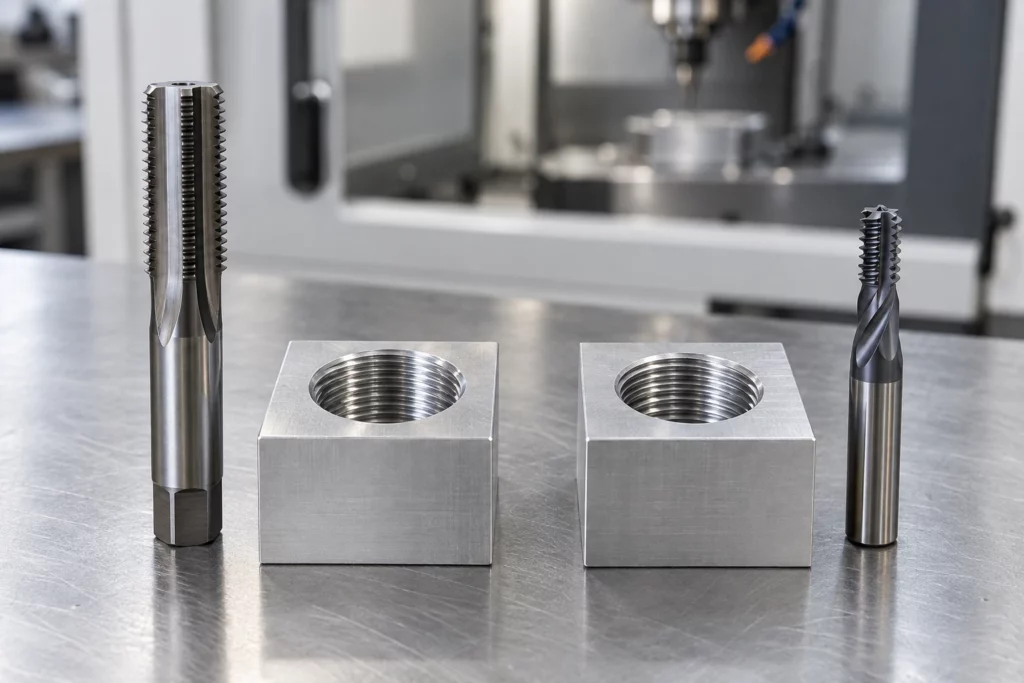
Tapping
A tap advances axially while its cutting edges or forming lobes create the complete thread profile. Because the tool engages around the circumference, torque, alignment, lubrication, chip control, and the prepared-hole diameter are important. Cut taps generate chips. Form taps displace suitable ductile material without chips, but they require a different hole size and should be approved for the material and specification.
Thread Milling
A thread mill rotates while the CNC moves it along a helical path. The cutter is smaller than the finished thread, so it engages a portion of the circumference at a time. The program controls diameter and direction, and suitable cutters can produce internal or external threads. The method needs enough bore access, tool clearance, machine interpolation, and stable workholding.
Choose by Hole Geometry
Through Holes
Through holes usually provide easier chip evacuation and fewer bottom-clearance constraints. For standard sizes and meaningful batch quantities, tapping often provides the most efficient cycle. A spiral-point cutting tap may push chips ahead through the opening when the material and application permit. Thread milling remains useful for large diameters, adjustable fits, mixed thread sizes, or parts where tool-breakage recovery influences the risk calculation.
Blind Holes
Blind holes need separate values for drilled depth, full thread depth, usable engagement, and bottom clearance. A tap has an incomplete lead before it produces full threads, and chips must have somewhere to go. Tap style, coolant delivery, chip evacuation, and reversal therefore matter. Thread milling can approach a shoulder with controlled axial positioning, but it still needs entry and exit clearance and cannot create usable thread beyond its programmed geometry. Do not specify “thread to bottom” without defining a manufacturable termination.
Choose by Material and Thread Specification
Material behavior affects torque, chips, tool wear, heat, and edge quality. Standard threads in machinable aluminum may favor tapping for speed, although chip packing or built-up edge still needs control. Tough stainless steels, high-temperature alloys, or expensive heat-treated parts may make the lower engagement and recovery advantages of thread milling more attractive. The supplier should confirm the exact alloy, hardness, and hole depth before choosing the route.
Thread size and form matter as much as material. Small standard threads may suit tapping, while larger diameters, special profiles, right- and left-hand variants, or adjustable fit classes can favor thread milling. A thread mill is not universal: its diameter, pitch capability, length, cutting form, and reach must match the feature.
Choose by Quantity and Cost of Failure
For a stable high-volume job, the shorter cycle of tapping can outweigh its lower flexibility. For prototypes and mixed families, thread milling may reduce the number of dedicated tools and allow diameter correction through offsets. The value of the workpiece also matters. Breaking a tap in an almost-complete housing can cost more than the saved cycle time; however, thread milling adds programming time and may use a more expensive cutter. Compare total route cost, not tool price alone.
Define the Thread Correctly on the Drawing
A process comparison cannot correct an incomplete specification. Use the same feature-based discipline applied to CNC machining tolerances, and include the following information:
- Thread standard and designation, nominal size, pitch or threads per inch, internal class or tolerance, and right- or left-hand direction.
- Through or blind condition, drilled depth, full thread depth, minimum usable engagement, entrance chamfer, and any bottom-clearance limit.
- Material grade and condition, heat treatment, coating or plating, quantity, critical datum relationships, and mating-fastener information.
- Inspection method, gauge standard, sampling level, first-article record, and any functional assembly test.
A complete CNC machining RFQ checklist also keeps model, drawing, revision, finish, and inspection assumptions consistent across bidders.
Verify the Sample and Production Route
Inspect the pre-hole as well as the finished thread. Confirm location, diameter, depth, chamfer, burr condition, and cleanliness. Use the specified GO and NO-GO gauges or another agreed method, then test the real mating fastener when assembly behavior matters. Record tool offsets and wear limits for thread milling, or torque, tap life, and chip-control checks for tapping. A first article should also confirm that coating, plating, or heat treatment does not invalidate the final fit.
Evaluate Supplier Capability Against the Part
CK Metal Tech publishes precision machining capabilities that include CNC milling, drilling, tapping, and related inspection resources. Its broader CNC machining services for precision metal parts provide the context for OEM process planning. The project review should still confirm whether tapping, thread milling, or another threading method is available and appropriate for the specific size, material, depth, tolerance, quantity, and inspection plan.
Conclusión
Use tapping when a standard internal thread, suitable material, controlled hole, and repeat quantity make cycle time the priority. Consider thread milling when fit adjustment, large or varied sizes, difficult materials, blind-hole constraints, or the cost of a trapped broken tap changes the economics. The drawing and sample plan should make the choice verifiable rather than leaving it to habit.
Preguntas frecuentes
Is Thread Milling Always More Accurate Than Tapping
No. Either process can make acceptable threads when the machine, tool, hole preparation, setup, and inspection suit the requirement. Thread milling offers useful diameter adjustment, but it does not replace process control.
Which Process Is Better for Blind Holes
It depends on usable depth, bottom clearance, material, chip control, thread size, and quantity. A suitable tap can be efficient; thread milling can improve control where evacuation or failure consequences are difficult.
Can One Thread Mill Cut Several Thread Sizes
Sometimes. A cutter may cover multiple diameters with a compatible pitch and profile, within its diameter and reach limits. Confirm the tool manufacturer’s range and the required thread form.
How Should an Internal Thread Be Inspected
Use the drawing’s specified gauge or measurement method and sampling plan. GO and NO-GO gauges are common, but depth, location, surface condition, and functional assembly may also require verification.
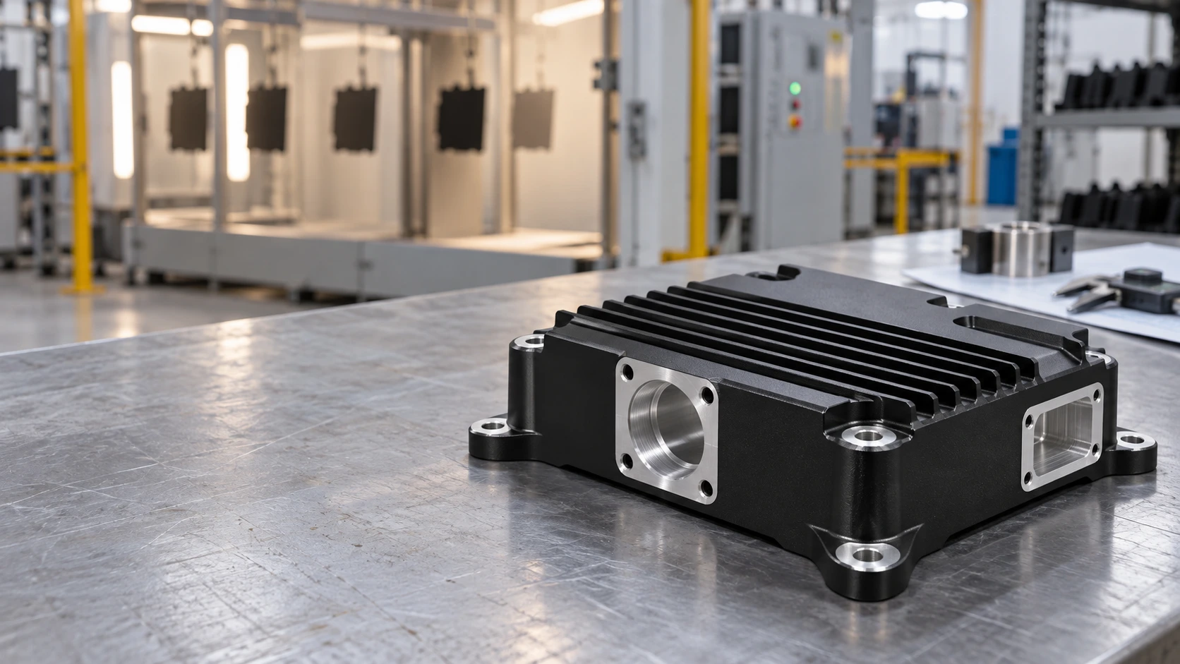
Can CNC-Machined Aluminum Housings Be Powder Coated? Thermal Interfaces, Fits, and Masking
22
octubre
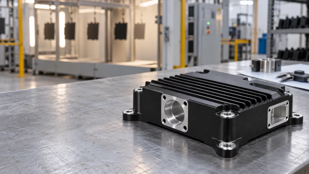
Can aluminum be powder coated after CNC machining? Yes, provided the drawing distinguishes cosmetic or protective surfaces from interfaces that must remain dimensionally, electrically, or thermally functional. A coating that performs well on an exterior wall can cause interference in a close fit, obstruct a thread, insulate a bonding point, or add thermal resistance at a heat-transfer joint.
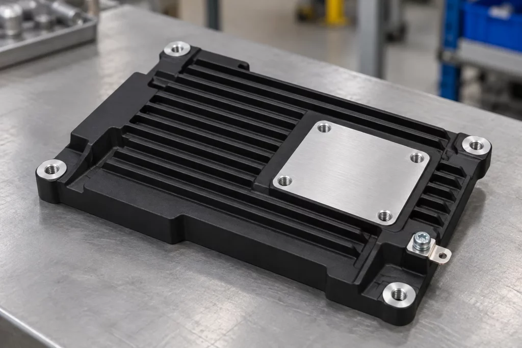
The review should therefore start with the finished assembly, not the color. CK Metal Tech’s aluminum alloy cooling and shielding cover plate illustrates why this distinction matters: one machined component may combine an exterior cover, mounting holes, grooves, structural bosses, shielding functions, and heat-dissipation duties. Those surfaces should not automatically receive the same finish treatment.
Map Functional Surfaces Before Coating
Create a finish map on the controlled drawing or model. Identify coated faces, cosmetic faces, no-coat zones, and surfaces whose final dimensions apply after finishing. A generic note such as “powder coat black” does not tell the manufacturer how the housing must assemble or perform.
Surfaces Commonly Suitable for Coating
Exterior walls, non-mating covers, guards, and handling surfaces are typical candidates when the selected pretreatment and powder system match the aluminum alloy and service environment. Coating can support appearance and surface protection, but corrosion, chemical exposure, ultraviolet exposure, and cleaning requirements still need project-specific confirmation.
Surfaces That Often Need Masking
Common no-coat candidates include bearing or bushing seats, locating datums, close-tolerance bores, sliding rails, O-ring lands, sealing faces, connector grounds, threaded holes, fastener seats, and direct thermal contact pads. The decision is functional rather than categorical: a clearance hole may tolerate film build, while a locating hole with the same nominal diameter may not.
Mask Boundaries Need Their Own Definition
A no-coat note should show where the boundary begins, which direction the mask may shift, and whether a small transition band is acceptable. This is important around countersinks, spotfaces, grooves, stepped bores, gasket lands, and thermal pads. Masking has practical placement variation, and the cured edge may not form a perfectly sharp geometric line. Keep the boundary away from a sealing path or precision datum where possible. If the transition itself affects function, dimension it from a stable feature and include it in the first-article inspection plan.
How Powder Coat Changes Functional Interfaces
Powder coating adds material to the surfaces it covers. The actual build depends on the powder, application, grounding, part geometry, racking, and cure route, so the drawing should define the finished requirement instead of assuming a universal allowance.
| Feature | Coating risk | Drawing or process control |
| Fits and threads | Film build reduces clearance and can obstruct engagement. | Mask, allow for the finish, or approve controlled post-coat machining. |
| Grounding points | The organic film can interrupt metal-to-metal electrical contact. | Mark bonding pads and define continuity or resistance verification. |
| Thermal interfaces | The coating and any trapped air can add resistance at a contact joint. | Keep direct-contact pads bare when required and define flatness, pressure, and interface material. |
| Sealing and datums | Build-up or an uneven mask edge can change seating and measurement references. | State whether dimensions apply before or after coating and locate mask boundaries. |
Fits and Threaded Features
Check each fit against its mating component and the finished-state tolerance. The same feature-level reasoning used for CNC machining tolerances applies after coating. Thread masks must protect the required diameter, lead-in, and usable depth. Forcing a screw through cured powder is not a controlled acceptance method because it can damage the finish and leave debris in the assembly.
Grounding and Thermal Contact
A designated grounding pad needs a clean boundary, a suitable fastener interface, and a defined verification method. Bare aluminum may also need a compatible protection strategy that preserves conductivity. For heat-transfer pads, evaluate coating together with contact area, surface flatness, clamping pressure, and any thermal interface material. A sample should be tested under representative heat load when temperature performance is critical.
Coordinate CNC Machining and Powder Coating as One Route
The safest sequence is established before chips are cut. Treat masking, finishing, and final inspection as part of the manufacturing plan rather than instructions added after machining.
- Review the current drawing, aluminum grade or approved alternative, functional interfaces, cosmetic zones, and operating environment.
- Machine the housing with any agreed allowance for surfaces controlled in the finished state; deburr edges without altering critical geometry.
- Clean and pretreat the part using a route compatible with the alloy, contamination condition, and specified coating system.
- Install plugs, caps, or high-temperature masking at the defined boundaries, then verify mask seating before spraying.
- Apply and cure the coating, remove masks cleanly, and inspect boundaries for lifting, chips, or unintended coverage.
- Complete only approved secondary machining or thread restoration, then clean the part and protect newly exposed aluminum as required.
An integrated review can connect the company’s precision machining capabilities with its powder coating service. The exact masking materials, post-coat operations, and inspection methods should still be confirmed for the part.
Verify the First Article Before Production
A first article should prove more than color and appearance. Use the actual mating components or representative gauges where possible, and record the drawing revision and coating specification used for approval.
- Dimensions: measure critical fits, datums, hole locations, and flatness in the state specified on the drawing.
- Assembly: install fasteners, covers, seals, rails, connectors, and locating features without forcing or finish damage.
- Electrical function: verify required bonding or shielding continuity at the specified contact points.
- Thermal function: check temperature performance under a representative load when the housing forms part of the heat path.
- Finish: inspect coverage, cure evidence, mask edges, handling damage, and cosmetic acceptance against an agreed reference.
Record nonconforming features separately. A part should not pass because its exterior looks uniform when a thread, bonding pad, thermal interface, or locating surface fails its own requirement.
What to Put in the Drawing and RFQ
Submit the 2D drawing and 3D model with material, quantity, coating system or performance requirement, color and texture, finished-state dimensions, no-coat zones, mask depth, thread callouts, grounding locations, thermal pads, inspection records, mating-part information, and sample approval criteria. Separate prototype quantity from expected production volume so the supplier can evaluate masking fixtures and process controls appropriately.
Conclusión
CNC-machined aluminum housings can be powder coated successfully when the finish map protects the part’s working interfaces. The design should preserve required clearance, thread engagement, electrical bonding, and thermal contact, while the process plan should connect machining, pretreatment, masking, coating, and finished-state inspection.
Preguntas frecuentes
Should Every Threaded Hole Be Masked
No. Masking depends on thread function, fastener fit, engagement depth, and the approved finishing route. The drawing should identify which threads must remain coating-free and how they will be checked.
Can Powder Coat Be Allowed for in a Close Fit
Sometimes, but the designer and manufacturer must agree on the final clearance and whether the controlling dimension applies before or after coating. Do not rely on a generic film allowance.
Should a Thermal Contact Pad Remain Bare
Often it should when direct metal contact is part of the heat path. Confirm the complete joint, including flatness, contact pressure, interface material, corrosion protection, and the required thermal test.
Is Post Coating Machining Acceptable
It may be, if the operation is planned. Control chips, protect the surrounding finish, re-inspect dimensions, and define how newly exposed aluminum will be handled.
Request a Joint Machining and Coating Review
Send CK Metal Tech the drawing revision, alloy, quantity, mating-part details, coating requirements, no-coat zones, thermal duty, grounding needs, and inspection expectations. Use the request a joint machining and coating review route to confirm the manufacturing sequence before quotation.
One Metal Supplier vs Multiple Vendors: How to Calculate Total Landed Cost
16
octubre
One metal supplier can reduce transfers between fabrication, finishing, and assembly, but supplier consolidation does not automatically lower total landed cost. Compare both routes at the same delivery destination, then add the buyer-side costs needed to turn delivered parts into accepted assemblies. Keep those layers separate: shipping and import charges belong in the landed-cost calculation; supplier administration, inventory, and integration costs belong in the broader sourcing decision.
For an OEM buying custom metal parts, this distinction prevents a lower piece price from hiding extra work. It also avoids calling every future operating expense a landed cost.
Define the Deliverable Before Comparing Vendors
Start with one controlled bill of materials and drawing revision. Specify material, finish, quantity, inspection criteria, packaging, destination, and assembly responsibility. A coated panel from one vendor cannot be compared directly with an assembled enclosure from another unless the missing operations are priced separately.
Distinguish process splitting from dual sourcing. Sending cutting to one shop and coating to another creates sequential handoffs. Qualifying two independent suppliers for the same finished assembly creates a backup route. These arrangements have different costs and continuity benefits; combining them under “multiple vendors” obscures the decision.
Calculate Total Landed Cost in Two Layers
The core shipment calculation is:
Landed cost = supplier invoices + separately charged tooling + packaging + freight + insurance + applicable duties, taxes, and clearance fees.
The International Trade Administration’s landed-cost guidance supports the product-plus-delivery approach. For metal parts, verify which charges are already included in each quotation. Add only costs outside the quoted scope, and use the same receiving location.
Then calculate a separate management metric:
Sourcing comparison cost = landed cost + buyer assembly and inspection + supplier administration + inventory carrying cost + evidence-based quality and disruption allowances.
This second formula is a purchasing decision tool, not a customs valuation or accounting rule. It does not include equipment operating costs over the product’s lifetime. Keep recoverable taxes and other accounting treatments identifiable for finance review rather than treating every cash payment as a permanent expense.
Normalize Quotes and Allocate Shared Charges
Use the same currency, demand period, release size, and named delivery point. Record the delivery term and which party pays each freight leg. A quote that includes shipping can appear expensive beside a factory-gate quote until the missing freight is added.
For international purchases, ask a qualified broker to verify classification, origin, applicable charges, and the relevant shipment date. Do not copy a tariff percentage from another part or last year’s order.
Allocate shared freight across a mixed shipment using a defensible driver, such as chargeable weight or occupied volume. Allocate tooling over the realistically committed program quantity, with tooling ownership shown separately. Show first-order and repeat-order costs independently; an optimistic lifetime volume can conceal a costly launch.
A Worked Example for One Thousand Assemblies
The following figures are hypothetical USD amounts, not CK Metal Tech quotations or tariff estimates. Both routes ultimately provide 1,000 accepted assemblies. The single supplier includes assembly in its invoice; the split route requires more buyer assembly work. Charges already included in supplier invoices are excluded from the other rows.
| Cost category | One supplier | Multiple vendors |
| Supplier invoices | $40,000 | $37,000 |
| Tooling and setup | $3,000 | $2,200 |
| Packaging freight and insurance | $1,800 | $3,300 |
| Illustrative import and clearance charges | $1,500 | $1,500 |
| Core landed cost | $46,300 | $44,000 |
| Buyer assembly and inspection | $800 | $3,300 |
| Supplier administration | $400 | $1,200 |
| Inventory carrying cost | $600 | $1,100 |
| Expected quality and rework allowance | $600 | $1,800 |
| Sourcing comparison total | $48,700 | $51,400 |
| Cost per accepted assembly | $48.70 | $51.40 |
Multiple vendors win the core landed-cost comparison by $2,300. After buyer-side costs are included, one supplier is lower by $2,700. This result follows the stated assumptions; it does not prove that consolidation is generally cheaper.
The decision changes if the split route reduces internal assembly effort, avoids quality losses, or provides a valuable qualified backup. Replace every allowance with program evidence before using this example for an award decision.
Measure Handoffs Without Double Counting
Map the route from cutting and forming through machining, coating, final inspection, and packing. Sheet metal fabrication may involve several linked operations, so track the transfers between them rather than counting suppliers alone.
For each handoff, record transport, protective packaging, receiving inspection, queue time, and revision-control responsibility. Estimate internal work from hours multiplied by an approved labor rate. Distinguish cash savings from staff capacity released: fewer purchase orders do not necessarily reduce payroll.
Estimate inventory carrying cost from average inventory value, the approved annual carrying rate, and the time period. Use historical rework and expedite costs where available. For a new program, show low, expected, and high cases rather than inventing a precise failure probability.
Avoid charging the same loss twice. If rejected units already reduce the accepted-unit denominator, check whether a separate scrap allowance repeats that loss. Likewise, do not add replacement freight when it is already included in a rework estimate.
Choose the Route and Test Its Weak Points
One supplier is attractive when interfaces dominate the program: welded frames must match machined brackets, coating boundaries affect fit, and completed assemblies require a coordinated release. Multiple vendors may be preferable when a process needs specialist qualification, capacity is constrained, or a genuinely independent backup is essential.
A backup is only useful if drawings, tooling access, qualification status, and available capacity make it executable. Two suppliers sharing the same critical subcontractor may still have a common interruption risk. Keep continuity requirements visible beside the cost comparison.
Test the decision against smaller releases, a rejected batch, an engineering change, and an expedited shipment. If the winner changes under a small assumption adjustment, resolve that uncertainty before committing the production route.
Request a Comparable Metal Manufacturing Quote
CK Metal Tech combines sheet metal processing, machining, stamping, powder coating, painting, and precision-component assembly. Review its metal manufacturing and assembly capabilities against the proposed route; process breadth alone does not establish capacity or suitability for a particular program.
Send the BOM, controlled drawings, quantities, destination, finish requirements, and acceptance plan. Ask CK Metal Tech to separate tooling from recurring prices and identify subcontracted operations, excluded services, and packing assumptions. Give alternative vendors the same package.
Conclusión
Choose the sourcing route using both delivered cost and the work required to obtain accepted assemblies. A transparent comparison can show that multiple vendors win on landed cost while one supplier wins after integration costs, or the reverse. Award the route whose cost assumptions and continuity requirements can be verified.
Preguntas frecuentes
Is one metal supplier always cheaper
No. Consolidation may reduce transfers and administration, while multiple vendors can provide specialist capability or backup capacity. Compare equivalent outputs and documented costs.
Is total landed cost the same as total cost of ownership
No. Landed cost addresses acquisition and delivery. Ownership cost extends into use, maintenance, and disposal. Buyer integration costs should remain a clearly labeled comparison layer.
How should tooling be included
Show the initial tooling payment separately, then allocate it across a defensible committed quantity for the unit comparison. Record ownership, maintenance responsibility, and repeat-order assumptions.
Should supplier management time count as a saving
Include it when comparing resource demand, but distinguish released staff capacity from actual cash savings. Use measured hours and an approved rate.
Request a Sourcing Route Review
Share the current drawings, BOM, delivery location, release schedule, and assembly scope with CK Metal Tech. Request a sourcing-route review to clarify included operations and compare the assumptions behind each quotation.