







-
Pembuatan prototipe dipercepat 1-3 hari & pemenuhan rantai pasokan yang fleksibel dan responsif.
-
Komitmen teguh terhadap pengiriman tepat waktu dan kualitas produk premium yang konsisten.
-
Pilihan material yang komprehensif + rangkaian lengkap perawatan finishing permukaan standar industri.
-
Penawaran harga langsung dari pabrik & rincian biaya yang sepenuhnya terbuka dan transparan.
-
Sistem mutu bersertifikasi ISO 9001:2015 / IATF 16949:2016
-
Layanan perakitan terintegrasi siap pakai: Kami menyediakan barang jadi lengkap yang siap pakai dan suku cadang terpisah.
Layanan Pengerjaan Logam Kustom Terpadu, Mulai dari Pembuatan Prototipe hingga Produksi Massal
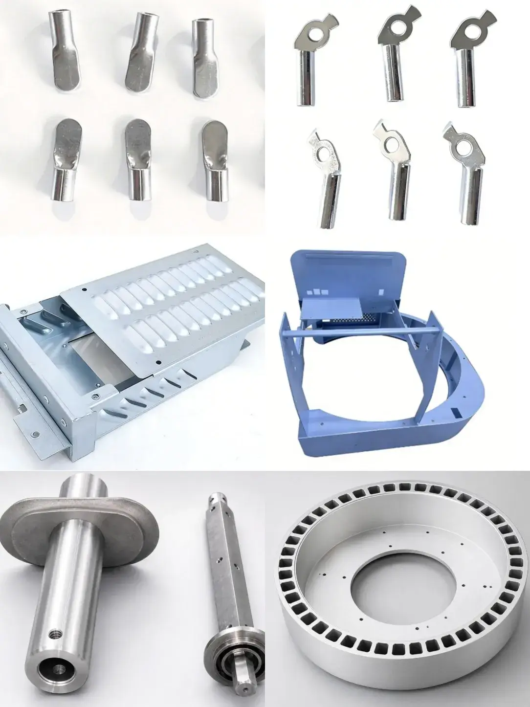
mendukung beragam aplikasi teknik dan manufaktur.
-
Harga Kompetitif & DFM
-
Dukungan Teknis 24/7
-
Pengerjaan Cepat, Waktu Tunggu Singkat, Tanpa Jumlah Pesanan Minimum (MOQ)
Verifikasi Sertifikasi Sesuai Permintaan: ISO 9001:2015 | IATF 16949:2016

tentang Chuangkai
Zhejiang Chuangkai Mechanical and Electrical Technology Co., Ltd. didirikan pada Maret 2003, dengan modal terdaftar sebesar 15 juta RMB. Perusahaan ini merupakan perusahaan teknologi tinggi yang mengintegrasikan desain dan manufaktur perkakas presisi, pencetakan logam presisi, pengolahan lembaran logam presisi, pemesinan presisi, pengecatan permukaan, pelapisan bubuk, dan perakitan komponen presisi. Saat ini, perusahaan memiliki 95 karyawan dan memiliki peralatan pengolahan presisi canggih serta bengkel standar, dengan total luas sekitar 13.500 meter persegi. Kami telah memperoleh sertifikasi sistem ISO9001, IATF16949, ISO45001, dan ISO14001.

Desain dan pembuatan perkakas stamping presisi
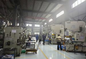
Peralatan utama untuk pengepresan di bengkel pengepresan: 18 set mesin pres presisi kecepatan tinggi dengan spesifikasi seperti 16 ton, 25 ton, 40 ton, 60 ton, 80 ton, 110 ton, 200 ton, dan 250 ton. Kecepatan mesin pres presisi kecepatan tinggi ini dapat mencapai 500 kali per menit.
Bahan untuk proses pencetakan: kuningan, perunggu fosfor, perunggu berilium, tembaga putih nikel, serta berbagai jenis baja dan bahan baja tahan karat, strip Ni, baja canai dingin, baja strip (termasuk yang sudah dilapisi), lembaran galvanis, baja karbon rendah, baja pegas, dan bahan komposit lainnya.
Pembuatan lembaran logam presisi
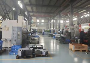
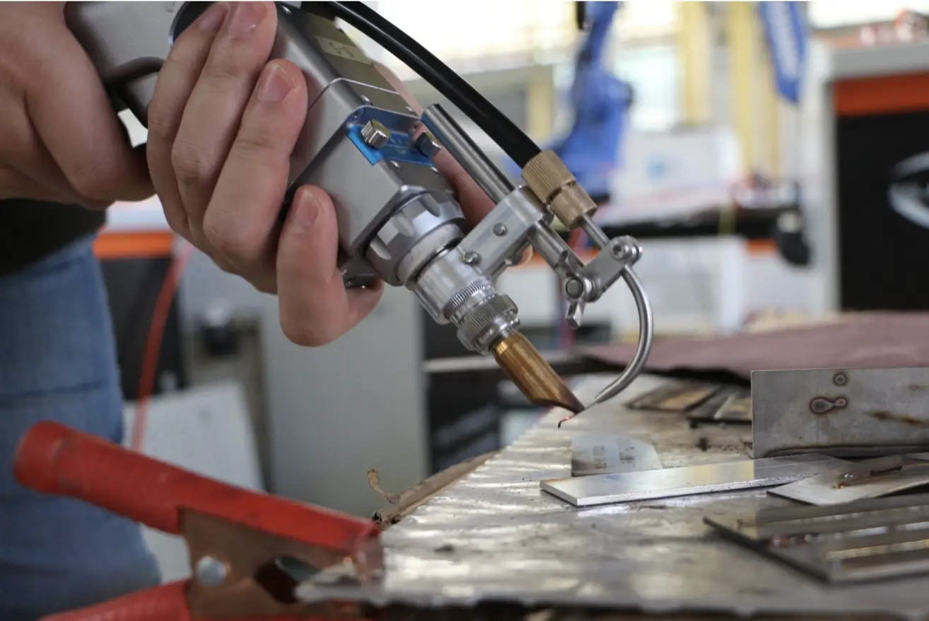
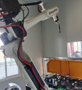
Bengkel pengolahan lembaran logam dilengkapi dengan peralatan pengolahan lembaran logam presisi, termasuk 2 mesin pemotong laser CNC canggih berskala besar, 1 mesin press punch CNC, 5 mesin bending CNC, serta mesin paku keling, mesin las, mesin gerinda, mesin penarik kawat, dan peralatan lainnya.
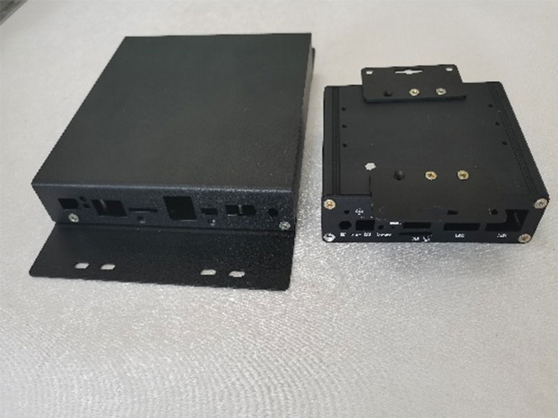
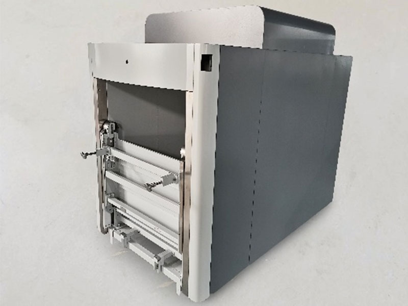
Produk olahan mencakup otomatisasi industri, peralatan medis, peralatan listrik, kotak listrik, kotak sambungan listrik, dan bidang lainnya. Mesin ini dapat melakukan pemrosesan presisi seperti pemotongan cepat dan pemrosesan lembaran logam pada material logam berikut: baja tahan karat, baja karbon, baja silikon, paduan aluminium, lembaran galvanis, lembaran berlapis aluminium-seng, dll.
Pelapisan Serbuk & Pengecatan
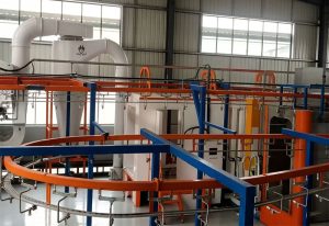
Satu jalur pelapisan bubuk otomatis;
Satu jalur pelapisan bubuk manual (untuk komponen besar dan kotak besar);
Satu jalur pengecatan manual (untuk komponen besar dan kotak besar);
Satu lini hibrida pelapisan bubuk dan pengecatan otomatis sedang dalam pembangunan.
Pemesinan presisi

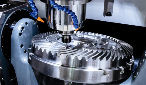
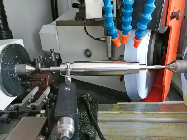
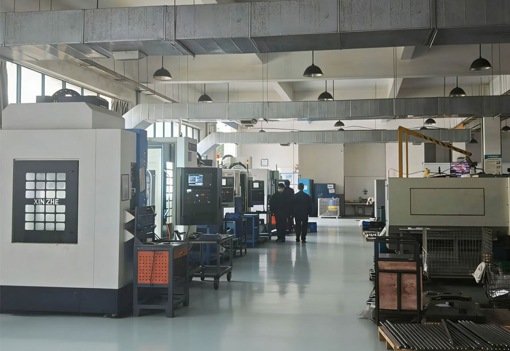
Bengkel permesinan ini dilengkapi dengan peralatan presisi, termasuk 6 set mesin CNC 4 sumbu, 1 set mesin bubut tipe Swiss 5 sumbu, 13 set mesin bubut CNC presisi, 4 set mesin penggilingan CNC, 16 set mesin bubut otomatis presisi Mingyang Taiwan, serta mesin bubut biasa presisi, mesin penggilingan digital display 3 sumbu presisi, mesin bubut bangku presisi, mesin penggilingan tepi otomatis Jizuan Taiwan, mesin penggulung ulir presisi, cetakan penggulung ulir, mesin penyadap presisi, mesin bor presisi, mesin penggilingan digital display Taiwan presisi, mesin pengasah pisau presisi, mesin pengasah silinder internal dan eksternal, mesin pengasah tanpa pusat, mesin gergaji, mesin pembersih dan pengering ultrasonik, mesin pemoles, mesin las listrik, mesin las busur, dan peralatan lainnya.
kita
Video pengantar
fakta menarik kami
Tidak perlu lagi mengkoordinasikan 5+ pemasok. Biaya - Produksi Cerdas: Integrasi vertikal + optimasi proses = pengurangan biaya 15 - 30% dibandingkan rantai pasokan yang terfragmentasi.
Kecepatan Pemasaran: Rekayasa simultan memangkas waktu tunggu hingga 40%. Penuhi tenggat waktu tanpa mengorbankan kualitas.
Minta Analisis DFM Gratis: Unggah gambar/sampel Anda. Teknisi kami akan mengidentifikasi optimalisasi biaya & efisiensi dalam waktu 48 jam.

perusahaan dibangun
0
modal terdaftar
0M
staf
0+
area pabrik
0+
kasus kami
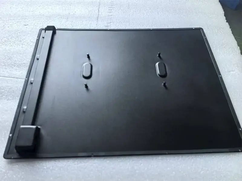
Gunakan proses peregangan sebagai pengganti teknologi dempul las+poles+kikis.
Gunakan proses peregangan sebagai pengganti pengelasan dan pemolesan. +Kikis dempul Teknologi
Atasi kendala teknis dan ciptakan komponen struktural logam berkualitas tinggi dan terjangkau untuk peralatan demonstrasi pengajaran:
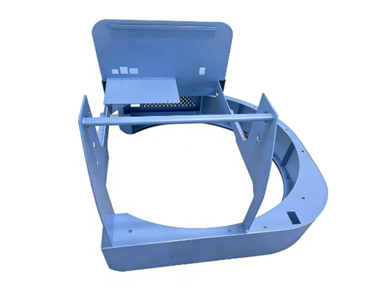
Ketika seorang pelanggan sedang mengembangkan komputer demonstrasi besar untuk pelatihan dan pengajaran, bagian struktur logam intinya menghadapi tantangan serius. Desain awal bagian tersebut menggunakan proses pengelasan untuk membuat bagian yang menonjol, tetapi pada tahap pengujian produk, kekencangan pengelasan yang buruk menyebabkan produk tersebut tidak dapat lolos uji utama. Pada saat yang sama, biaya proses pengelasan yang tinggi membuat harga komponen jauh lebih tinggi daripada pesaing, pengiriman proyek sudah dekat, dan pelanggan menghadapi tekanan besar terkait kualitas dan biaya.
Identifikasi titik-titik permasalahan secara akurat dan berikan respons cepat untuk mengatasinya:
Setelah memahami kesulitan pelanggan, kami segera membentuk tim teknis khusus. Dalam seminar teknis pertama, kami menganalisis secara mendalam akar penyebab buruknya kekedapan udara pada pengelasan. Meskipun dengan mengoptimalkan parameter pengelasan dan memperkenalkan mesin pengelasan serta personel yang tepat, kami telah berhasil memecahkan masalah kekedapan udara dan memenuhi persyaratan kualitas awal pelanggan, namun masalah biaya pengelasan yang tinggi masih belum terselesaikan.
Rencana inovatif, dua arah:
Tim teknis tidak berhenti sampai di situ. Setelah banyak putaran diskusi internal dan komunikasi erat dengan pelanggan, kami telah mengusulkan solusi mendasar: mengganti pengelasan asli dengan proses pencetakan dan peregangan terintegrasi.+Pemolesan+Pengikis dempul Craft. Ini tidak hanya sepenuhnya menghilangkan risiko kekencangan pengelasan dari sumbernya, tetapi juga secara signifikan mengurangi biaya produksi dan memberikan kemungkinan bagi produk untuk meraih pangsa pasar yang lebih besar.
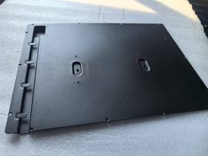
Raihlah 'Mustahil', penuhi janji:
Umpan balik pelanggan telah mempertimbangkan penambahan stempel. Rencana tersebut memang perlu dipertimbangkan, tetapi pemasok lain mengatakan hal itu tidak dapat diwujudkan. Dalam menghadapi pertanyaan tersebut, kami sangat yakin bahwa 'kita belajar dengan melakukan'. Berdasarkan akumulasi teknologi yang mendalam, kami memberikan saran optimasi utama kepada pelanggan, termasuk:
Sesuaikan sudut kemiringan tarik untuk mengoptimalkan fluiditas material, dan pilih merek pelat baja canai dingin tertentu dengan kinerja tarik yang lebih baik.
Hasil luar biasa, dipuji oleh pelanggan:
Setelah rencana ditetapkan, kami melakukan beberapa putaran pengujian proses yang ketat dan verifikasi sampel. Komponen akhir yang dikirimkan sepenuhnya memenuhi persyaratan desain dan standar kinerja pelanggan. Pelanggan sangat puas dengan hasilnya, dan tidak hanya memberikan pujian tinggi: "Ini adalah produk sempurna sesuai desain ideal saya!", tetapi juga menyampaikan terima kasih yang tulus atas kemampuan tim Chuangkai dalam mengatasi masalah-masalah sulit. Kami telah berhasil membantu pelanggan dalam periode pengiriman yang mendesak, sekaligus menyelesaikan masalah kualitas dan biaya yang sulit, serta membantu produk mereka mendapatkan keunggulan dalam persaingan pasar.
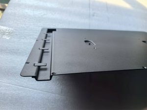
Mengatasi Hambatan Teknis untuk Menghasilkan Komponen Logam Berkualitas Tinggi dan Hemat Biaya untuk Tampilan dan Sistem Pendidikan
Tantangannya:
Seorang klien yang mengembangkan komputer demonstrasi besar untuk pelatihan dan pendidikan menghadapi masalah kritis dengan komponen struktural logam utama. Desain awal menggunakan tonjolan yang dilas. Namun, selama pengujian produk, integritas penyegelan las yang buruk menyebabkan kegagalan. Yang memperparah masalah, biaya proses pengelasan yang tinggi membuat komponen mereka jauh lebih mahal daripada pesaing. Dengan tenggat waktu proyek yang semakin dekat, klien berada di bawah tekanan besar untuk menyelesaikan tantangan kualitas dan biaya.
Respons Cepat & Solusi Awal Kami:
Setelah mengetahui permasalahan klien, kami segera membentuk tim teknis khusus. Dalam tinjauan teknis awal, kami menganalisis secara menyeluruh akar penyebab kegagalan penyegelan. Melalui uji coba optimasi parameter pengelasan yang ekstensif dan implementasi strategis pengelasan robotik, kami berhasil mencapai integritas penyegelan yang dibutuhkan, memenuhi spesifikasi kualitas klien.
Mengidentifikasi Masalah yang Lebih Dalam & Mengusulkan Inovasi:
Meskipun masalah penyegelan langsung telah teratasi, masalah mendasar berupa biaya produksi yang sangat tinggi tetap ada. Menolak untuk berpuas diri, tim kerja kami melakukan brainstorming internal secara intensif dan menjaga komunikasi yang erat dengan klien. Kami mengusulkan solusi transformatif: mengganti rakitan yang dilas dengan komponen satu bagian yang dibentuk melalui proses stamping dan deep drawing. Pendekatan ini menjanjikan:
- Hilangkan akar penyebab kegagalan penyegelan yang melekat pada pengelasan.
- Raih pengurangan biaya yang signifikan dengan menyederhanakan produksi.
- Meningkatkan daya saing pasar** untuk produk akhir klien.
Menerobos Batasan yang Mustahil:
Klien mengungkapkan bahwa mereka sebelumnya telah menjajaki metode pencetakan, tetapi pemasok lain menganggapnya tidak layak untuk bagian ini. Berpegang pada keyakinan kami bahwa 'Bukti terletak pada praktik', kami memanfaatkan keahlian teknis kami untuk mengusulkan optimasi desain yang sangat penting:
- 1. Menyesuaikan sudut penarikan untuk meningkatkan aliran material.
- 2. Menentukan baja canai dingin kelas lebih tinggi dengan sifat penarikan dalam yang unggul.
Hasil yang Sukses:
Setelah melalui proses pembuatan prototipe dan pengujian validasi yang ketat berdasarkan desain yang telah kami optimalkan, kami mengirimkan komponen final. Hasilnya luar biasa, selaras sempurna dengan maksud desain dan persyaratan kinerja klien. Klien menyatakan kepuasan yang mendalam, memberikan pujian tinggi: "Ini adalah produk sempurna yang saya bayangkan dalam desain saya!" Mereka secara eksplisit berterima kasih kepada ChuangKai karena telah menyelesaikan masalah teknis yang terus-menerus mereka hadapi. Kami memungkinkan klien untuk memenuhi tenggat waktu kritis mereka sekaligus mengatasi cacat kualitas dan hambatan biaya, secara signifikan meningkatkan daya saing pasar produk mereka.
Studi Kasus tentang Perbaikan untuk Kerusakan Poros Mesin Pertanian
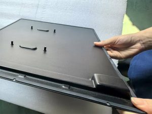
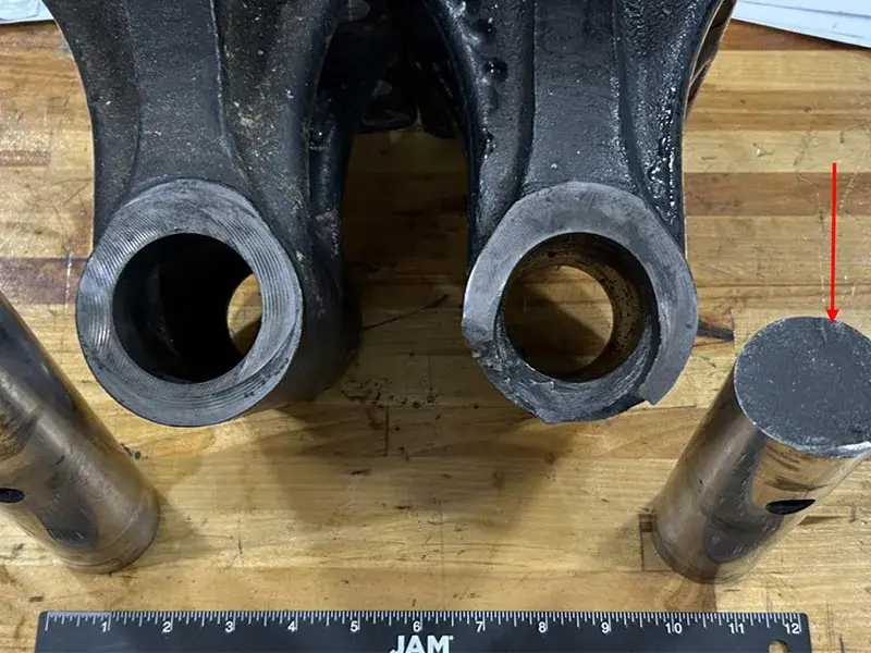
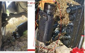
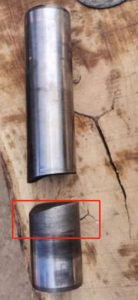
Pada Juli 2024, seorang pelanggan memberikan umpan balik bahwa poros mesin pemanen gabungan mereka mengalami kerusakan selama operasi di lapangan, dan pelanggan akhir sangat khawatir karena biji-bijian yang matang tidak dapat dipanen dengan lancar. Awalnya mereka mengira bahwa mungkin bahan baku poros 40CrNiMoA atau proses perlakuan panasnya tidak memenuhi persyaratan. Kami telah menerima bantuan mereka, poros yang patah dianalisis untuk pertama kalinya, dan disimpulkan bahwa itu bukan bahan baku dan ada masalah dengan prosesnya, tetapi dirancang oleh pelanggan. Musim tidak memperhitungkan kondisi kerja peralatan yang kompleks. Dan bahaya tersembunyi kelelahan gaya satu arah, persyaratan pelanggan. Perlakuan panas tingkat kekerasan tinggi secara keseluruhan menghasilkan kekerasan inti yang tinggi, yang mudah menghasilkan kerusakan akibat kelelahan. Setelah analisis, kami menyarankan untuk mengadopsi penyesuaian kualitas keseluruhan ditambah proses pendinginan induksi permukaan menggantikan perlakuan panas asli. Kekerasan keseluruhan yang tinggi. Proses ini mengurangi kekerasan inti dan meningkatkan kekerasan permukaan luar, yang memenuhi ketahanan aus, dan mengirimkannya ke pelanggan sesuai dengan proses yang disarankan. Sampel baru mencapai hasil yang sangat baik dalam percobaan lapangan kedua. Membuahkan hasil, umpan balik positif.
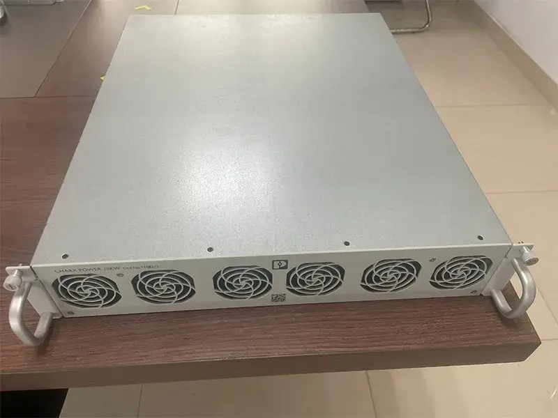
Proses peningkatan penutup kotak catu daya
Seorang pelanggan asal Jerman dari perusahaan kami memiliki kotak kombinasi yang mengalami kesulitan pada tahap desain. Jika menggunakan metode paku keling, kotak akan menonjol dari permukaan dan memengaruhi fungsinya. Jika menggunakan metode pengelasan, tampilannya tidak memenuhi persyaratan dan biayanya tinggi. Setelah menghubungi kami, kami kebetulan memiliki kasus sukses dalam proyek lain. Kami dapat menyelesaikan masalah pelanggan dengan sangat baik menggunakan paku keling kepala datar ganda dan lubang sekrup. Kami telah mengirimkan sampel kepada pelanggan.
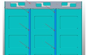
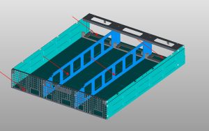
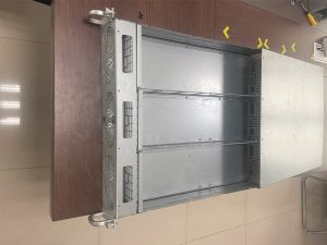
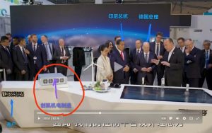
Mereka sangat puas dan meraih hasil yang memuaskan di pameran Hanover.,Mendapatkan pujian bulat!

Mitra Solusi Manufaktur Lengkap Anda
Mitra Solusi Manufaktur Lengkap Anda
Dari Konsep hingga Penyelesaian – Direkayasa dengan Presisi untuk Kesuksesan Global
Di ChuangKai, kami menghilangkan kerumitan pengadaan dari berbagai vendor. Sebagai produsen terintegrasi vertikal yang mengkhususkan diri dalam solusi ODM & OEM, kami menghadirkan produksi komponen presisi tinggi yang lancar melalui kemampuan komprehensif kami:
Layanan Manufaktur Terpadu:
- Pemesinan: Penggilingan/Pembubutan CNC, Pemesinan Swiss
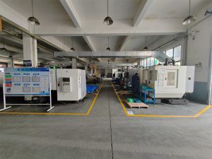
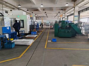
- Fabrikasi Logam: Pemotongan Laser, Pembengkokan, Pengelasan
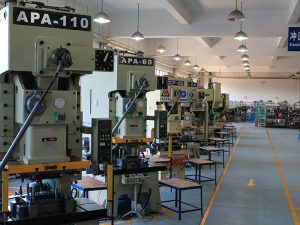
- Pencetakan & Pembentukan: Pencetakan Cetakan Progresif, Penarikan Dalam
- Pembuatan Perkakas & Cetakan: Desain & Pembuatan Cetakan/Die Kustom
- Perlakuan Permukaan: Pelapisan Serbuk, Pengecatan Semprot
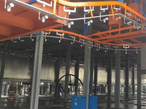
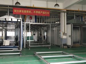
- Perakitan & Pengujian: Perlengkapan Lengkap, Validasi Kualitas
Keunggulan ODM/OEM untuk Bisnis Anda:
Inovasi Desain
Tim teknik kami berkolaborasi dengan Anda untuk mengoptimalkan desain demi kemudahan manufaktur, efisiensi biaya, dan kinerja – mengubah konsep menjadi produk siap pasar.
Akuntabilitas Satu Sumber
Tidak perlu lagi mengkoordinasikan 5+ pemasok. Kami mengelola seluruh alur kerja di bawah satu atap:
Desain → Pembuatan Prototipe → Pembuatan Peralatan → Pengadaan Bahan Baku → Produksi → Penyelesaian Akhir → Perakitan → Logistik
Produksi Hemat Biaya
Integrasi vertikal + optimasi proses = pengurangan biaya 15-30% dibandingkan dengan rantai pasokan yang terfragmentasi.
| Kecepatan Peluncuran ke Pasar |
Rekayasa simultan memangkas waktu tunggu hingga 40%. Penuhi tenggat waktu tanpa mengorbankan kualitas.
| Kualitas Terintegrasi |
Proses bersertifikasi ISO dengan ketertelusuran digital. Pelaporan PPAP, FAIR, dan CPK tersedia.
√ Industri yang Kami Layani:
Otomotif | Mesin Industri | Alat Kesehatan | Energi Terbarukan | Robotika | Pembangkit Listrik Nuklir
Mengapa Klien Global Memilih Kami:
Pemecah Masalah: Seperti [Studi Kasus Peralatan Demonstrasi Pengajaran] di mana kami mengganti rakitan yang dilas dengan komponen hasil cetakan terintegrasi – mengatasi kebocoran + memangkas biaya 25%.
Kapasitas yang Dapat Diperluas: Dukungan mulai dari prototipe NPI hingga produksi massal lebih dari 1 juta unit.
Ketangkasan Teknis: Lebih dari 20 insinyur siap menangani GD&T yang kompleks, toleransi ketat (±0,01 mm), dan tantangan material.
→ Minta Analisis DFM Gratis
Unggah gambar/sampel Anda. Teknisi kami akan mengidentifikasi optimalisasi biaya & efisiensi dalam waktu 48 jam.
Produk

Pertanyaan yang Sering Diajukan (FAQ)
Bagian ini menjawab pertanyaan umum tentang produk, layanan, dan kebijakan mekanik dan elektrik kami. Ini membantu Anda menemukan informasi dengan cepat tanpa perlu menghubungi dukungan.
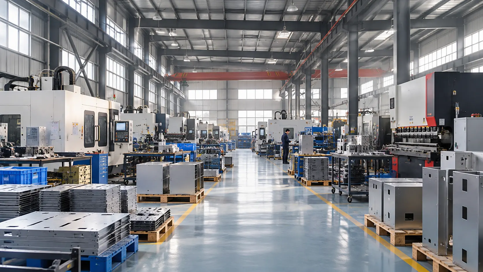
Kekuatan inti kami terletak pada integrasi seluruh rantai industri, mulai dari pemesinan presisi, pemrosesan lembaran logam presisi, produksi stamping, desain dan manufaktur kontrak, perawatan permukaan profesional dengan penyemprotan hingga perakitan produk akhir, dan penerapan sistem manajemen kualitas yang luar biasa di seluruh proses. Ini berarti pelanggan tidak perlu mengkoordinasikan banyak pemasok untuk mendapatkan layanan yang efisien, terkoordinasi, dan konsisten. Kontrol kualitas ketat kami diterapkan di setiap环节, memastikan bahwa yang pada akhirnya dikirimkan bukan hanya suku cadang atau produk yang memenuhi persyaratan, tetapi juga solusi keseluruhan yang stabil, andal, dan berstandar tinggi, secara efektif membantu pelanggan mempersingkat waktu pengiriman, mengurangi biaya, dan meningkatkan efisiensi rantai pasokan.
Pemrosesan komponen non-standar yang disesuaikan. Hal ini bergantung pada kompleksitas produk. Jangka waktu pengiriman umum biasanya antara 2 hingga 4 minggu.
25
Pengalaman bertahun-tahun















Hubungi kami
artikel terbaru
artikel terbaru
Butuh solusi mekanik dan elektrik atau punya pertanyaan? Hubungi kami!
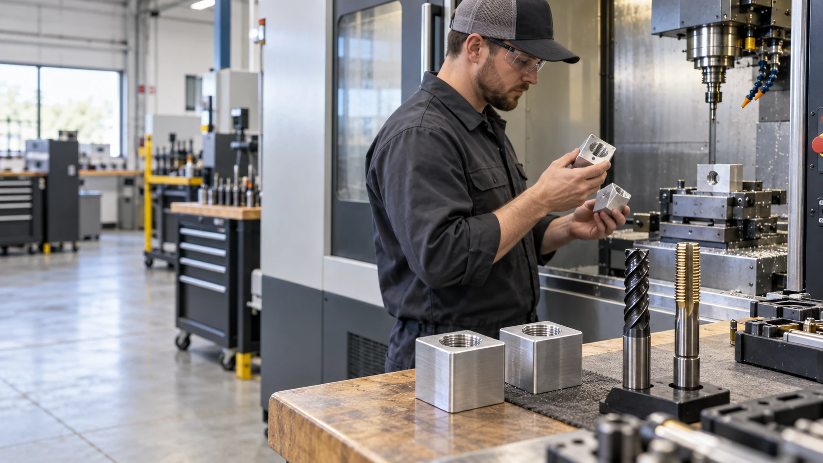
Tapping vs. Thread Milling for CNC-Machined OEM Parts: Choosing the Right Internal Thread Process
23
Oktober
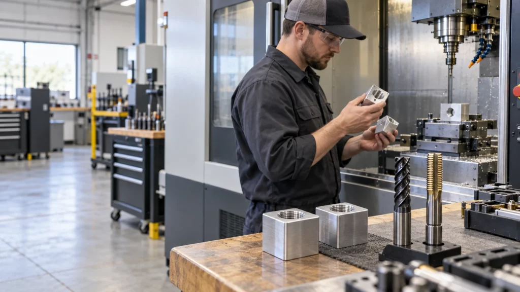
The choice between tapping and thread milling depends on the hole, material, thread specification, production quantity, machine capability, and cost of failure. Tapping is usually the faster route for repeat production of standard internal threads. Thread milling offers more control over thread size and fit, handles a wider range of diameters with fewer tools, and can reduce the consequence of a tool failure in a valuable part.
Neither process is universally better. A through-hole in a stable aluminum part may favor tapping, while a large thread, difficult material, expensive near-finished component, or close fit adjustment may justify thread milling. Blind-hole geometry and usable thread depth can change the answer again.
Tapping vs Thread Milling at a Glance
| Decision factor | Tapping | Thread milling |
| Cycle time | Often faster for standard repeated threads. | Usually longer because the tool follows a helical path. |
| Tool flexibility | One tap normally matches a specific size, pitch, and form. | One cutter may cover multiple diameters that share a compatible pitch and profile. |
| Fit adjustment | Limited after the tap and hole preparation are selected. | Tool-path offsets can adjust the finished thread within process limits. |
| Failure risk | A broken tap may be difficult to remove from the part. | A smaller cutter may be easier to recover from, but breakage can still damage the feature. |
| Machine need | Requires controlled feed and rotation appropriate to the tapping method. | Requires CNC helical interpolation, suitable control, rigidity, and access. |
How Each Process Cuts an Internal Thread
Both methods begin with a prepared hole, but their tool engagement is different. The drawing must specify the finished thread; the process planner then selects the pre-hole, tool, cutting data, and inspection route.
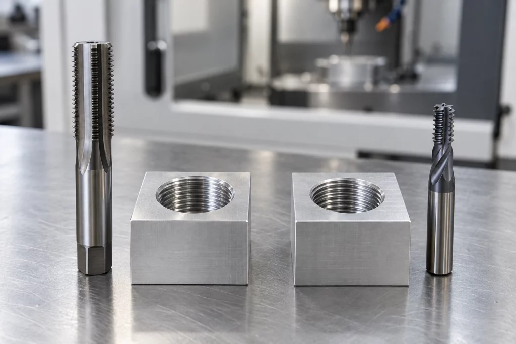
Tapping
A tap advances axially while its cutting edges or forming lobes create the complete thread profile. Because the tool engages around the circumference, torque, alignment, lubrication, chip control, and the prepared-hole diameter are important. Cut taps generate chips. Form taps displace suitable ductile material without chips, but they require a different hole size and should be approved for the material and specification.
Thread Milling
A thread mill rotates while the CNC moves it along a helical path. The cutter is smaller than the finished thread, so it engages a portion of the circumference at a time. The program controls diameter and direction, and suitable cutters can produce internal or external threads. The method needs enough bore access, tool clearance, machine interpolation, and stable workholding.
Choose by Hole Geometry
Through Holes
Through holes usually provide easier chip evacuation and fewer bottom-clearance constraints. For standard sizes and meaningful batch quantities, tapping often provides the most efficient cycle. A spiral-point cutting tap may push chips ahead through the opening when the material and application permit. Thread milling remains useful for large diameters, adjustable fits, mixed thread sizes, or parts where tool-breakage recovery influences the risk calculation.
Blind Holes
Blind holes need separate values for drilled depth, full thread depth, usable engagement, and bottom clearance. A tap has an incomplete lead before it produces full threads, and chips must have somewhere to go. Tap style, coolant delivery, chip evacuation, and reversal therefore matter. Thread milling can approach a shoulder with controlled axial positioning, but it still needs entry and exit clearance and cannot create usable thread beyond its programmed geometry. Do not specify “thread to bottom” without defining a manufacturable termination.
Choose by Material and Thread Specification
Material behavior affects torque, chips, tool wear, heat, and edge quality. Standard threads in machinable aluminum may favor tapping for speed, although chip packing or built-up edge still needs control. Tough stainless steels, high-temperature alloys, or expensive heat-treated parts may make the lower engagement and recovery advantages of thread milling more attractive. The supplier should confirm the exact alloy, hardness, and hole depth before choosing the route.
Thread size and form matter as much as material. Small standard threads may suit tapping, while larger diameters, special profiles, right- and left-hand variants, or adjustable fit classes can favor thread milling. A thread mill is not universal: its diameter, pitch capability, length, cutting form, and reach must match the feature.
Choose by Quantity and Cost of Failure
For a stable high-volume job, the shorter cycle of tapping can outweigh its lower flexibility. For prototypes and mixed families, thread milling may reduce the number of dedicated tools and allow diameter correction through offsets. The value of the workpiece also matters. Breaking a tap in an almost-complete housing can cost more than the saved cycle time; however, thread milling adds programming time and may use a more expensive cutter. Compare total route cost, not tool price alone.
Define the Thread Correctly on the Drawing
A process comparison cannot correct an incomplete specification. Use the same feature-based discipline applied to CNC machining tolerances, and include the following information:
- Thread standard and designation, nominal size, pitch or threads per inch, internal class or tolerance, and right- or left-hand direction.
- Through or blind condition, drilled depth, full thread depth, minimum usable engagement, entrance chamfer, and any bottom-clearance limit.
- Material grade and condition, heat treatment, coating or plating, quantity, critical datum relationships, and mating-fastener information.
- Inspection method, gauge standard, sampling level, first-article record, and any functional assembly test.
A complete CNC machining RFQ checklist also keeps model, drawing, revision, finish, and inspection assumptions consistent across bidders.
Verify the Sample and Production Route
Inspect the pre-hole as well as the finished thread. Confirm location, diameter, depth, chamfer, burr condition, and cleanliness. Use the specified GO and NO-GO gauges or another agreed method, then test the real mating fastener when assembly behavior matters. Record tool offsets and wear limits for thread milling, or torque, tap life, and chip-control checks for tapping. A first article should also confirm that coating, plating, or heat treatment does not invalidate the final fit.
Evaluate Supplier Capability Against the Part
CK Metal Tech publishes precision machining capabilities that include CNC milling, drilling, tapping, and related inspection resources. Its broader CNC machining services for precision metal parts provide the context for OEM process planning. The project review should still confirm whether tapping, thread milling, or another threading method is available and appropriate for the specific size, material, depth, tolerance, quantity, and inspection plan.
Kesimpulan
Use tapping when a standard internal thread, suitable material, controlled hole, and repeat quantity make cycle time the priority. Consider thread milling when fit adjustment, large or varied sizes, difficult materials, blind-hole constraints, or the cost of a trapped broken tap changes the economics. The drawing and sample plan should make the choice verifiable rather than leaving it to habit.
Pertanyaan yang Sering Diajukan (FAQ)
Is Thread Milling Always More Accurate Than Tapping
No. Either process can make acceptable threads when the machine, tool, hole preparation, setup, and inspection suit the requirement. Thread milling offers useful diameter adjustment, but it does not replace process control.
Which Process Is Better for Blind Holes
It depends on usable depth, bottom clearance, material, chip control, thread size, and quantity. A suitable tap can be efficient; thread milling can improve control where evacuation or failure consequences are difficult.
Can One Thread Mill Cut Several Thread Sizes
Sometimes. A cutter may cover multiple diameters with a compatible pitch and profile, within its diameter and reach limits. Confirm the tool manufacturer’s range and the required thread form.
How Should an Internal Thread Be Inspected
Use the drawing’s specified gauge or measurement method and sampling plan. GO and NO-GO gauges are common, but depth, location, surface condition, and functional assembly may also require verification.
Can CNC-Machined Aluminum Housings Be Powder Coated? Thermal Interfaces, Fits, and Masking
22
Oktober
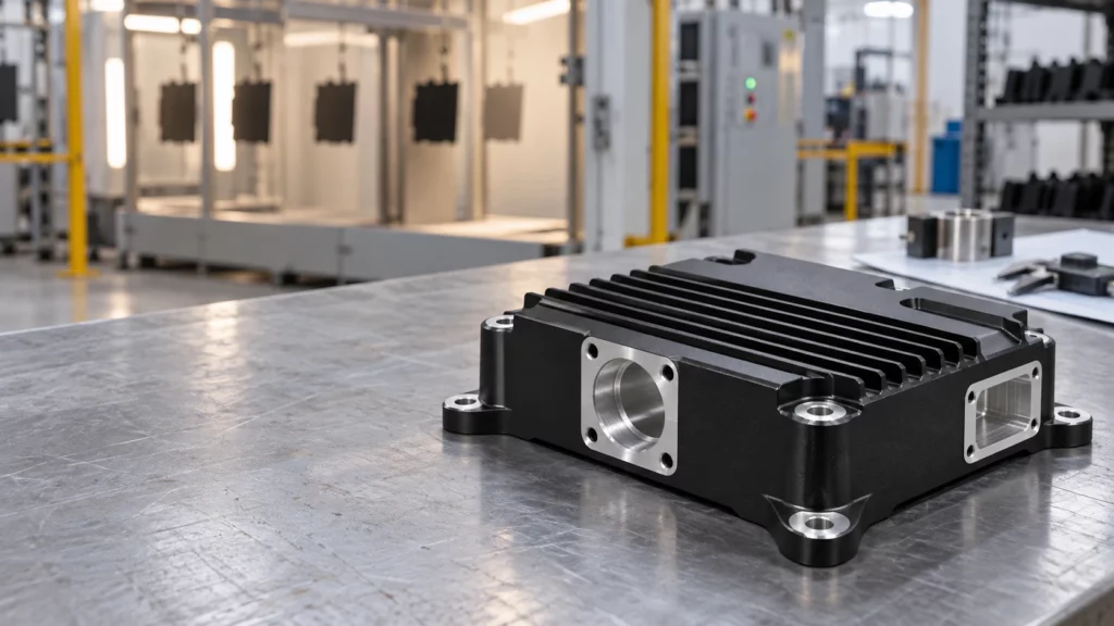
Can aluminum be powder coated after CNC machining? Yes, provided the drawing distinguishes cosmetic or protective surfaces from interfaces that must remain dimensionally, electrically, or thermally functional. A coating that performs well on an exterior wall can cause interference in a close fit, obstruct a thread, insulate a bonding point, or add thermal resistance at a heat-transfer joint.
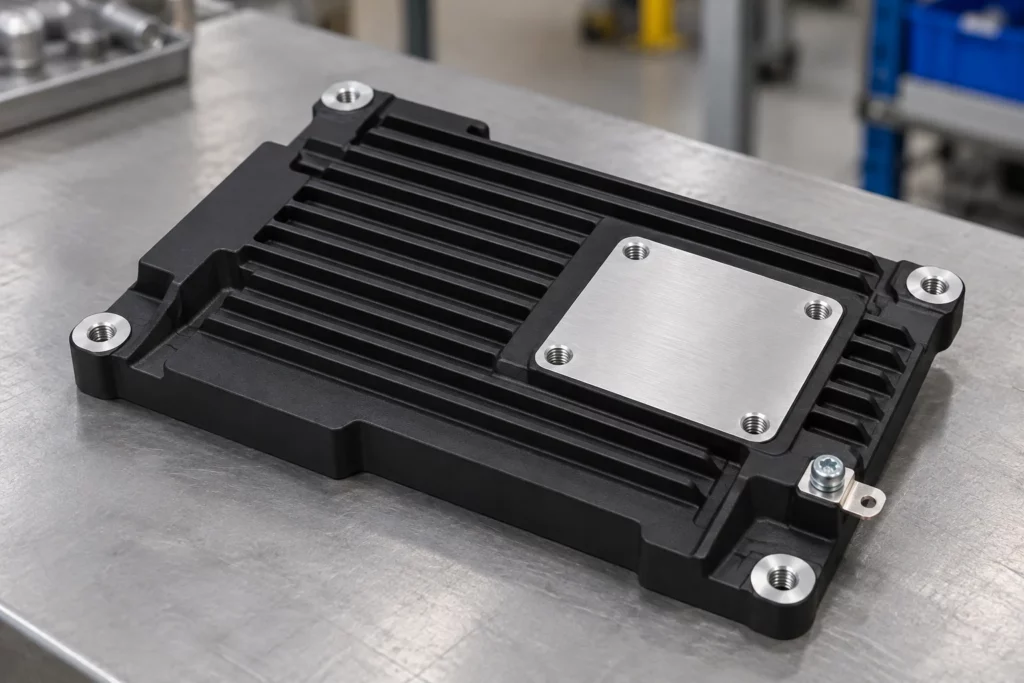
The review should therefore start with the finished assembly, not the color. CK Metal Tech’s aluminum alloy cooling and shielding cover plate illustrates why this distinction matters: one machined component may combine an exterior cover, mounting holes, grooves, structural bosses, shielding functions, and heat-dissipation duties. Those surfaces should not automatically receive the same finish treatment.
Map Functional Surfaces Before Coating
Create a finish map on the controlled drawing or model. Identify coated faces, cosmetic faces, no-coat zones, and surfaces whose final dimensions apply after finishing. A generic note such as “powder coat black” does not tell the manufacturer how the housing must assemble or perform.
Surfaces Commonly Suitable for Coating
Exterior walls, non-mating covers, guards, and handling surfaces are typical candidates when the selected pretreatment and powder system match the aluminum alloy and service environment. Coating can support appearance and surface protection, but corrosion, chemical exposure, ultraviolet exposure, and cleaning requirements still need project-specific confirmation.
Surfaces That Often Need Masking
Common no-coat candidates include bearing or bushing seats, locating datums, close-tolerance bores, sliding rails, O-ring lands, sealing faces, connector grounds, threaded holes, fastener seats, and direct thermal contact pads. The decision is functional rather than categorical: a clearance hole may tolerate film build, while a locating hole with the same nominal diameter may not.
Mask Boundaries Need Their Own Definition
A no-coat note should show where the boundary begins, which direction the mask may shift, and whether a small transition band is acceptable. This is important around countersinks, spotfaces, grooves, stepped bores, gasket lands, and thermal pads. Masking has practical placement variation, and the cured edge may not form a perfectly sharp geometric line. Keep the boundary away from a sealing path or precision datum where possible. If the transition itself affects function, dimension it from a stable feature and include it in the first-article inspection plan.
How Powder Coat Changes Functional Interfaces
Powder coating adds material to the surfaces it covers. The actual build depends on the powder, application, grounding, part geometry, racking, and cure route, so the drawing should define the finished requirement instead of assuming a universal allowance.
| Feature | Coating risk | Drawing or process control |
| Fits and threads | Film build reduces clearance and can obstruct engagement. | Mask, allow for the finish, or approve controlled post-coat machining. |
| Grounding points | The organic film can interrupt metal-to-metal electrical contact. | Mark bonding pads and define continuity or resistance verification. |
| Thermal interfaces | The coating and any trapped air can add resistance at a contact joint. | Keep direct-contact pads bare when required and define flatness, pressure, and interface material. |
| Sealing and datums | Build-up or an uneven mask edge can change seating and measurement references. | State whether dimensions apply before or after coating and locate mask boundaries. |
Fits and Threaded Features
Check each fit against its mating component and the finished-state tolerance. The same feature-level reasoning used for CNC machining tolerances applies after coating. Thread masks must protect the required diameter, lead-in, and usable depth. Forcing a screw through cured powder is not a controlled acceptance method because it can damage the finish and leave debris in the assembly.
Grounding and Thermal Contact
A designated grounding pad needs a clean boundary, a suitable fastener interface, and a defined verification method. Bare aluminum may also need a compatible protection strategy that preserves conductivity. For heat-transfer pads, evaluate coating together with contact area, surface flatness, clamping pressure, and any thermal interface material. A sample should be tested under representative heat load when temperature performance is critical.
Coordinate CNC Machining and Powder Coating as One Route
The safest sequence is established before chips are cut. Treat masking, finishing, and final inspection as part of the manufacturing plan rather than instructions added after machining.
- Review the current drawing, aluminum grade or approved alternative, functional interfaces, cosmetic zones, and operating environment.
- Machine the housing with any agreed allowance for surfaces controlled in the finished state; deburr edges without altering critical geometry.
- Clean and pretreat the part using a route compatible with the alloy, contamination condition, and specified coating system.
- Install plugs, caps, or high-temperature masking at the defined boundaries, then verify mask seating before spraying.
- Apply and cure the coating, remove masks cleanly, and inspect boundaries for lifting, chips, or unintended coverage.
- Complete only approved secondary machining or thread restoration, then clean the part and protect newly exposed aluminum as required.
An integrated review can connect the company’s precision machining capabilities with its powder coating service. The exact masking materials, post-coat operations, and inspection methods should still be confirmed for the part.
Verify the First Article Before Production
A first article should prove more than color and appearance. Use the actual mating components or representative gauges where possible, and record the drawing revision and coating specification used for approval.
- Dimensions: measure critical fits, datums, hole locations, and flatness in the state specified on the drawing.
- Assembly: install fasteners, covers, seals, rails, connectors, and locating features without forcing or finish damage.
- Electrical function: verify required bonding or shielding continuity at the specified contact points.
- Thermal function: check temperature performance under a representative load when the housing forms part of the heat path.
- Finish: inspect coverage, cure evidence, mask edges, handling damage, and cosmetic acceptance against an agreed reference.
Record nonconforming features separately. A part should not pass because its exterior looks uniform when a thread, bonding pad, thermal interface, or locating surface fails its own requirement.
What to Put in the Drawing and RFQ
Submit the 2D drawing and 3D model with material, quantity, coating system or performance requirement, color and texture, finished-state dimensions, no-coat zones, mask depth, thread callouts, grounding locations, thermal pads, inspection records, mating-part information, and sample approval criteria. Separate prototype quantity from expected production volume so the supplier can evaluate masking fixtures and process controls appropriately.
Kesimpulan
CNC-machined aluminum housings can be powder coated successfully when the finish map protects the part’s working interfaces. The design should preserve required clearance, thread engagement, electrical bonding, and thermal contact, while the process plan should connect machining, pretreatment, masking, coating, and finished-state inspection.
Pertanyaan yang Sering Diajukan (FAQ)
Should Every Threaded Hole Be Masked
No. Masking depends on thread function, fastener fit, engagement depth, and the approved finishing route. The drawing should identify which threads must remain coating-free and how they will be checked.
Can Powder Coat Be Allowed for in a Close Fit
Sometimes, but the designer and manufacturer must agree on the final clearance and whether the controlling dimension applies before or after coating. Do not rely on a generic film allowance.
Should a Thermal Contact Pad Remain Bare
Often it should when direct metal contact is part of the heat path. Confirm the complete joint, including flatness, contact pressure, interface material, corrosion protection, and the required thermal test.
Is Post Coating Machining Acceptable
It may be, if the operation is planned. Control chips, protect the surrounding finish, re-inspect dimensions, and define how newly exposed aluminum will be handled.
Request a Joint Machining and Coating Review
Send CK Metal Tech the drawing revision, alloy, quantity, mating-part details, coating requirements, no-coat zones, thermal duty, grounding needs, and inspection expectations. Use the request a joint machining and coating review route to confirm the manufacturing sequence before quotation.
One Metal Supplier vs Multiple Vendors: How to Calculate Total Landed Cost
16
Oktober
One metal supplier can reduce transfers between fabrication, finishing, and assembly, but supplier consolidation does not automatically lower total landed cost. Compare both routes at the same delivery destination, then add the buyer-side costs needed to turn delivered parts into accepted assemblies. Keep those layers separate: shipping and import charges belong in the landed-cost calculation; supplier administration, inventory, and integration costs belong in the broader sourcing decision.
For an OEM buying custom metal parts, this distinction prevents a lower piece price from hiding extra work. It also avoids calling every future operating expense a landed cost.
Define the Deliverable Before Comparing Vendors
Start with one controlled bill of materials and drawing revision. Specify material, finish, quantity, inspection criteria, packaging, destination, and assembly responsibility. A coated panel from one vendor cannot be compared directly with an assembled enclosure from another unless the missing operations are priced separately.
Distinguish process splitting from dual sourcing. Sending cutting to one shop and coating to another creates sequential handoffs. Qualifying two independent suppliers for the same finished assembly creates a backup route. These arrangements have different costs and continuity benefits; combining them under “multiple vendors” obscures the decision.
Calculate Total Landed Cost in Two Layers
The core shipment calculation is:
Landed cost = supplier invoices + separately charged tooling + packaging + freight + insurance + applicable duties, taxes, and clearance fees.
The International Trade Administration’s landed-cost guidance supports the product-plus-delivery approach. For metal parts, verify which charges are already included in each quotation. Add only costs outside the quoted scope, and use the same receiving location.
Then calculate a separate management metric:
Sourcing comparison cost = landed cost + buyer assembly and inspection + supplier administration + inventory carrying cost + evidence-based quality and disruption allowances.
This second formula is a purchasing decision tool, not a customs valuation or accounting rule. It does not include equipment operating costs over the product’s lifetime. Keep recoverable taxes and other accounting treatments identifiable for finance review rather than treating every cash payment as a permanent expense.
Normalize Quotes and Allocate Shared Charges
Use the same currency, demand period, release size, and named delivery point. Record the delivery term and which party pays each freight leg. A quote that includes shipping can appear expensive beside a factory-gate quote until the missing freight is added.
For international purchases, ask a qualified broker to verify classification, origin, applicable charges, and the relevant shipment date. Do not copy a tariff percentage from another part or last year’s order.
Allocate shared freight across a mixed shipment using a defensible driver, such as chargeable weight or occupied volume. Allocate tooling over the realistically committed program quantity, with tooling ownership shown separately. Show first-order and repeat-order costs independently; an optimistic lifetime volume can conceal a costly launch.
A Worked Example for One Thousand Assemblies
The following figures are hypothetical USD amounts, not CK Metal Tech quotations or tariff estimates. Both routes ultimately provide 1,000 accepted assemblies. The single supplier includes assembly in its invoice; the split route requires more buyer assembly work. Charges already included in supplier invoices are excluded from the other rows.
| Cost category | One supplier | Multiple vendors |
| Supplier invoices | $40,000 | $37,000 |
| Tooling and setup | $3,000 | $2,200 |
| Packaging freight and insurance | $1,800 | $3,300 |
| Illustrative import and clearance charges | $1,500 | $1,500 |
| Core landed cost | $46,300 | $44,000 |
| Buyer assembly and inspection | $800 | $3,300 |
| Supplier administration | $400 | $1,200 |
| Inventory carrying cost | $600 | $1,100 |
| Expected quality and rework allowance | $600 | $1,800 |
| Sourcing comparison total | $48,700 | $51,400 |
| Cost per accepted assembly | $48.70 | $51.40 |
Multiple vendors win the core landed-cost comparison by $2,300. After buyer-side costs are included, one supplier is lower by $2,700. This result follows the stated assumptions; it does not prove that consolidation is generally cheaper.
The decision changes if the split route reduces internal assembly effort, avoids quality losses, or provides a valuable qualified backup. Replace every allowance with program evidence before using this example for an award decision.
Measure Handoffs Without Double Counting
Map the route from cutting and forming through machining, coating, final inspection, and packing. Sheet metal fabrication may involve several linked operations, so track the transfers between them rather than counting suppliers alone.
For each handoff, record transport, protective packaging, receiving inspection, queue time, and revision-control responsibility. Estimate internal work from hours multiplied by an approved labor rate. Distinguish cash savings from staff capacity released: fewer purchase orders do not necessarily reduce payroll.
Estimate inventory carrying cost from average inventory value, the approved annual carrying rate, and the time period. Use historical rework and expedite costs where available. For a new program, show low, expected, and high cases rather than inventing a precise failure probability.
Avoid charging the same loss twice. If rejected units already reduce the accepted-unit denominator, check whether a separate scrap allowance repeats that loss. Likewise, do not add replacement freight when it is already included in a rework estimate.
Choose the Route and Test Its Weak Points
One supplier is attractive when interfaces dominate the program: welded frames must match machined brackets, coating boundaries affect fit, and completed assemblies require a coordinated release. Multiple vendors may be preferable when a process needs specialist qualification, capacity is constrained, or a genuinely independent backup is essential.
A backup is only useful if drawings, tooling access, qualification status, and available capacity make it executable. Two suppliers sharing the same critical subcontractor may still have a common interruption risk. Keep continuity requirements visible beside the cost comparison.
Test the decision against smaller releases, a rejected batch, an engineering change, and an expedited shipment. If the winner changes under a small assumption adjustment, resolve that uncertainty before committing the production route.
Request a Comparable Metal Manufacturing Quote
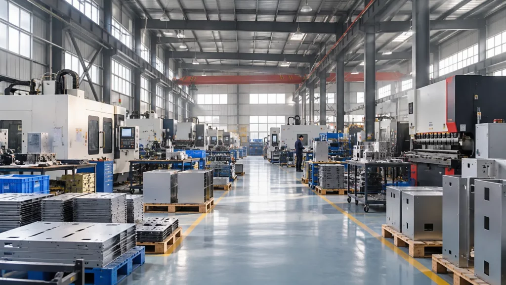
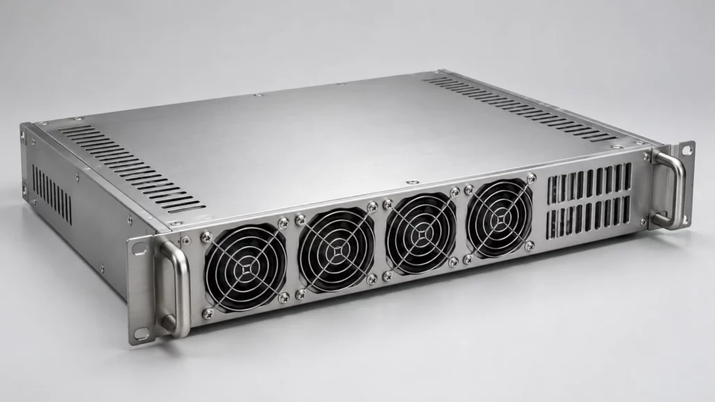
CK Metal Tech combines sheet metal processing, machining, stamping, powder coating, painting, and precision-component assembly. Review its metal manufacturing and assembly capabilities against the proposed route; process breadth alone does not establish capacity or suitability for a particular program.
Send the BOM, controlled drawings, quantities, destination, finish requirements, and acceptance plan. Ask CK Metal Tech to separate tooling from recurring prices and identify subcontracted operations, excluded services, and packing assumptions. Give alternative vendors the same package.
Kesimpulan
Choose the sourcing route using both delivered cost and the work required to obtain accepted assemblies. A transparent comparison can show that multiple vendors win on landed cost while one supplier wins after integration costs, or the reverse. Award the route whose cost assumptions and continuity requirements can be verified.
Pertanyaan yang Sering Diajukan (FAQ)
Is one metal supplier always cheaper
No. Consolidation may reduce transfers and administration, while multiple vendors can provide specialist capability or backup capacity. Compare equivalent outputs and documented costs.
Is total landed cost the same as total cost of ownership
No. Landed cost addresses acquisition and delivery. Ownership cost extends into use, maintenance, and disposal. Buyer integration costs should remain a clearly labeled comparison layer.
How should tooling be included
Show the initial tooling payment separately, then allocate it across a defensible committed quantity for the unit comparison. Record ownership, maintenance responsibility, and repeat-order assumptions.
Should supplier management time count as a saving
Include it when comparing resource demand, but distinguish released staff capacity from actual cash savings. Use measured hours and an approved rate.
Request a Sourcing Route Review
Share the current drawings, BOM, delivery location, release schedule, and assembly scope with CK Metal Tech. Request a sourcing-route review to clarify included operations and compare the assumptions behind each quotation.