







-
Fabrication accélérée de prototypes en 1 à 3 jours et chaîne d'approvisionnement flexible et réactive
-
Engagement ferme à assurer des livraisons ponctuelles et une qualité de produit supérieure et constante.
-
Large choix de matériaux + gamme complète de traitements de finition de surface conformes aux normes industrielles
-
Prix direct usine et ventilation des coûts totalement transparente.
-
Système de qualité certifié conforme aux normes ISO 9001:2015 / IATF 16949:2016
-
Service d'assemblage intégré clé en main : nous fournissons des produits finis complets et prêts à l'emploi ainsi que des pièces détachées.
Service complet de fabrication métallique sur mesure, du prototypage à la production en série
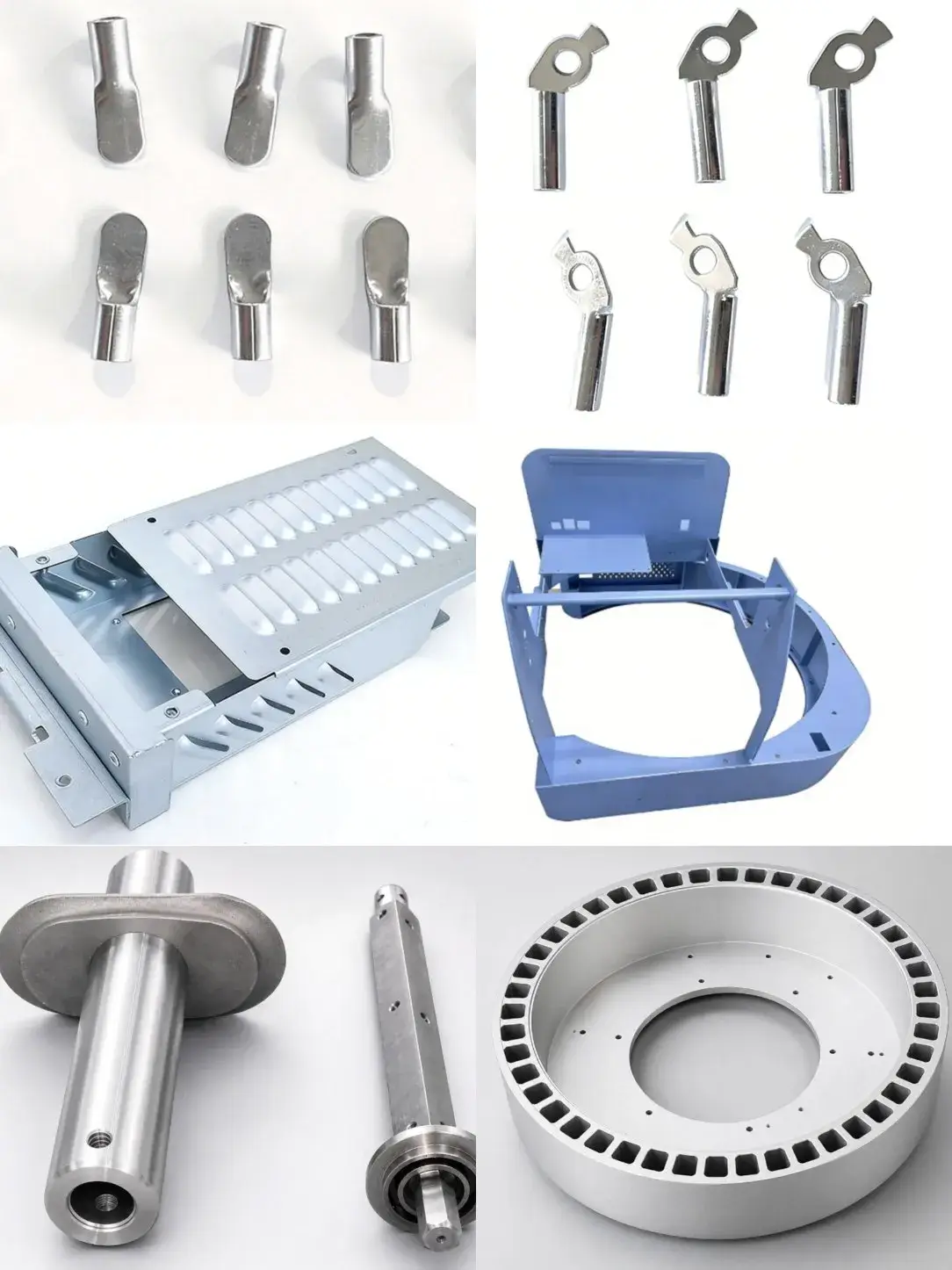
soutenir diverses applications d'ingénierie et de fabrication.
-
Prix compétitifs et DFM
-
Assistance technique 24h/24 et 7j/7
-
Délais de livraison courts, pas de quantité minimale de commande.
Vérification des certifications à la demande : ISO 9001:2015 | IATF 16949:2016

à propos de Chuangkai
La société Zhejiang Chuangkai Mechanical and Electrical Technology Co., Ltd., fondée en mars 2003 avec un capital social de 15 millions de RMB, est une entreprise de haute technologie spécialisée dans la conception et la fabrication d'outillage de précision, l'emboutissage de précision, le travail de la tôle de précision, l'usinage de précision, la peinture de surface, le revêtement en poudre et l'assemblage de composants de précision. Elle emploie actuellement 95 personnes et dispose d'équipements de pointe pour l'usinage de précision ainsi que d'ateliers aux normes établies, sur une superficie totale d'environ 13 500 mètres carrés. Elle est certifiée ISO 9001, IATF 16949, ISO 45001 et ISO 14001.

Conception et fabrication d'outillage d'emboutissage de précision
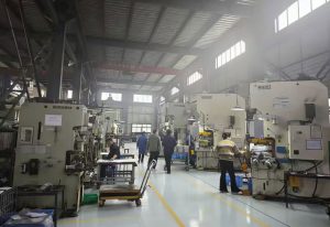
Principaux équipements d'emboutissage de l'atelier : 18 presses à poinçonner de précision à grande vitesse, d'une capacité de 16 à 250 tonnes. La cadence de ces presses peut atteindre 500 poinçonnages par minute.
Matériaux pour le traitement d'emboutissage : laiton, bronze phosphoreux, bronze au béryllium, cuivre blanc nickelé, ainsi que divers types d'acier et d'acier inoxydable, bandes de Ni, acier laminé à froid, bande d'acier (y compris pré-plaquée), tôles galvanisées, acier à faible teneur en carbone, acier à ressort et autres matériaux composites.
fabrication de tôles de précision
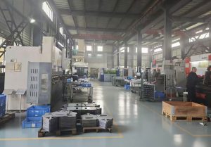
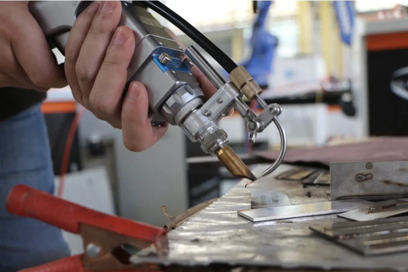
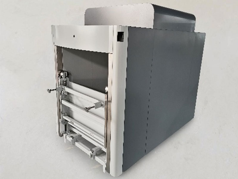
L'atelier de tôlerie est équipé de machines de traitement de tôlerie de précision, notamment 2 machines de découpe laser CNC de grande taille et de pointe, 1 presse à poinçonner CNC, 5 machines de pliage CNC, ainsi que des riveteuses, des machines à souder, des meuleuses, des machines à tréfiler et d'autres équipements.
Les produits transformés couvrent des domaines tels que l'automatisation industrielle, les équipements médicaux, les équipements électriques, les coffrets électriques, les boîtes de jonction et bien d'autres. L'entreprise réalise des usinages de précision, notamment la découpe rapide et le travail de la tôle, sur les matériaux suivants : acier inoxydable, acier au carbone, acier au silicium, alliage d'aluminium, tôle galvanisée, tôle zinguée-aluminium, etc.
Peinture en poudre
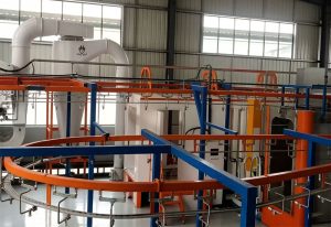
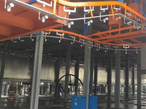
Une ligne de revêtement en poudre automatique ;
Une ligne de revêtement en poudre manuelle (pour les grandes pièces et les grandes boîtes) ;
Une ligne de peinture manuelle (pour les grandes pièces et les grandes boîtes) ;
Une ligne hybride automatique de revêtement en poudre et de peinture est en construction.
Usinage de précision

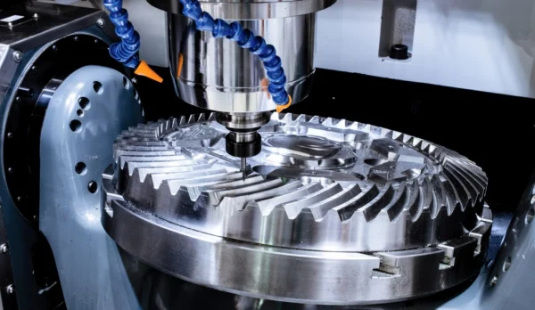
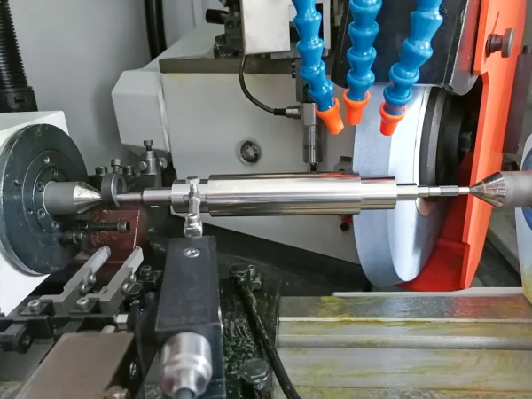
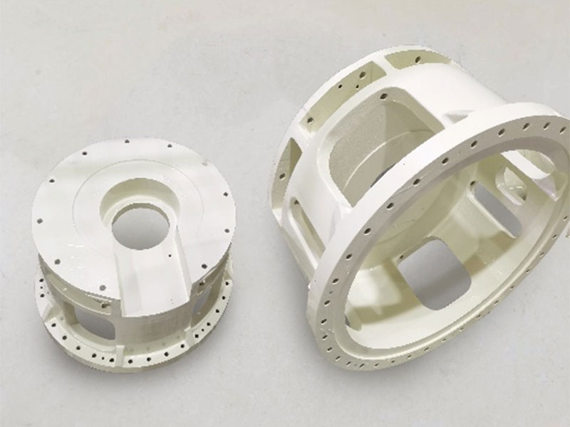
L'atelier d'usinage est équipé de machines de précision, notamment 6 machines CNC 4 axes, 1 tour suisse 5 axes, 13 tours CNC de précision, 4 fraiseuses CNC, 16 tours automatiques de précision Mingyang (Taïwan), ainsi que des tours ordinaires de précision, des fraiseuses numériques 3 axes de précision, des tours d'établi de précision, des fraiseuses automatiques de bord Jizuan (Taïwan), des rouleuses de filetage de précision, des matrices de roulage de filetage, des taraudeuses de précision, des perceuses de précision, des fraiseuses numériques de précision (Taïwan), des affûteuses de couteaux de précision, des rectifieuses cylindriques internes et externes, des rectifieuses sans centre, des scies, des machines de nettoyage et de séchage par ultrasons, des polisseuses, des soudeuses électriques, des soudeuses à l'arc et d'autres équipements.
notre
Vidéo d'introduction
nos faits amusants
Plus besoin de coordonner plus de 5 fournisseurs. Production intelligente et économique : intégration verticale et optimisation des processus = réduction des coûts de 15 à 30 % par rapport aux chaînes d’approvisionnement fragmentées.
Accélération de la mise sur le marché : l’ingénierie simultanée réduit les délais de 40 %. Respectez les échéances sans compromettre la qualité.
Demandez une analyse DFM gratuite : téléchargez vos dessins/échantillons. Nos ingénieurs identifieront les optimisations de coûts et d’efficacité sous 48 heures.

l'entreprise est construite
0
capital social
0M
personnel
0+
zone industrielle
0+
notre cas
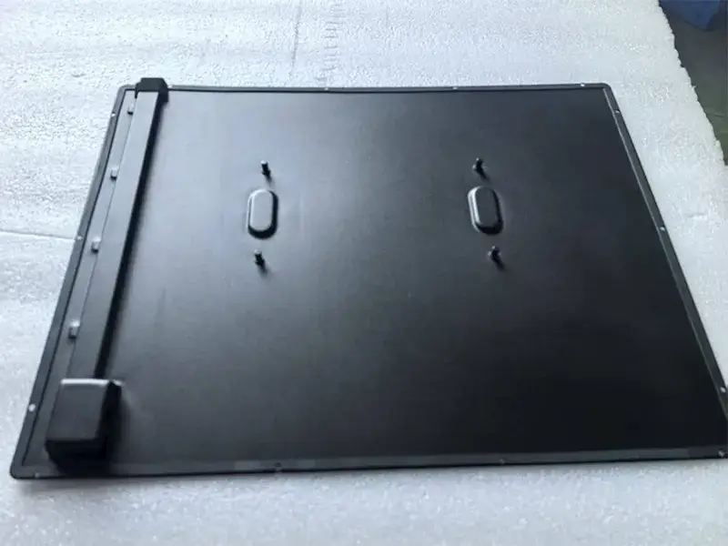
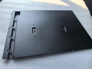
Utiliser le procédé d'étirage en remplacement de la technologie de soudage, polissage et grattage du mastic.
Utiliser le procédé d'étirage en remplacement du soudage et du polissage +Mastic à gratter Technologie
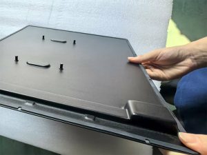
Surmontez les obstacles techniques et créez des pièces structurelles métalliques de haute qualité et à prix compétitif pour les équipements de démonstration pédagogique :
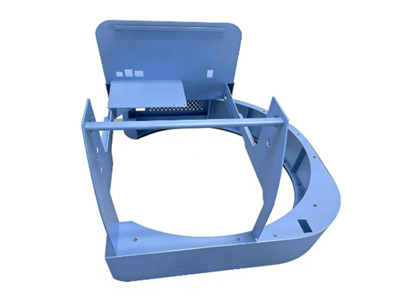
Lors du développement d'un ordinateur de démonstration de grande taille destiné à la formation et à l'enseignement, un client a rencontré des difficultés majeures au niveau de ses pièces métalliques structurelles principales. La conception initiale prévoyait l'utilisation du soudage pour la réalisation des parties saillantes, mais lors des tests, la faible étanchéité des soudures a empêché le produit de réussir le test clé. Parallèlement, le coût élevé du soudage a engendré un prix nettement supérieur à celui de la concurrence, et alors que la livraison du projet était imminente, le client était soumis à une forte pression en matière de qualité et de coûts.
Identifier précisément les points sensibles et réagir rapidement pour les résoudre :
Après avoir compris la situation difficile du client, nous avons rapidement mis en place une équipe technique dédiée. Lors du premier séminaire technique, nous avons analysé en profondeur les causes profondes du défaut d'étanchéité des soudures. Bien que l'optimisation des paramètres de soudage et l'introduction de nouvelles machines à souder nous aient permis de résoudre le problème d'étanchéité et de satisfaire aux exigences de qualité initiales du client, le problème du coût élevé du soudage demeure.
Plan novateur, à deux volets :
L'équipe technique ne s'est pas arrêtée là. Après de nombreuses discussions internes et une étroite collaboration avec nos clients, nous avons proposé une solution fondamentale : remplacer la soudure d'origine par un procédé intégré d'emboutissage et d'étirage, suivi d'un polissage et d'un ébavurage. Cette solution élimine non seulement tout risque lié à l'étanchéité de la soudure à la source, mais réduit également considérablement les coûts de production et permet au produit de conquérir un marché plus vaste.
Saisir l'impossible, tenir sa promesse :
Les retours clients ont évoqué la possibilité d'étendre le projet d'estampage, mais d'autres fournisseurs ont affirmé que c'était irréalisable. Face à ces interrogations, nous restons convaincus que « c'est en pratiquant qu'on apprend ». Forts d'une solide expérience technologique, nous proposons à nos clients des suggestions d'optimisation clés, notamment :
Ajustez l'angle de pente de traction pour optimiser la fluidité du matériau et choisissez une marque spécifique de tôle d'acier laminée à froid offrant de meilleures performances de traction.
Résultats excellents, salués par les clients :
Une fois le plan établi, nous avons mené plusieurs séries de tests rigoureux et de vérifications d'échantillons. Les pièces livrées répondent parfaitement aux exigences de conception et aux normes de performance du client. Ce dernier s'est déclaré extrêmement satisfait et a non seulement exprimé son enthousiasme : « C'est le produit idéal, conforme à ma conception ! », mais il a également remercié sincèrement l'équipe de Chuangkai pour sa capacité à surmonter les difficultés rencontrées. Nous avons ainsi pu répondre aux exigences de nos clients dans des délais de livraison très courts, tout en résolvant les problèmes complexes de qualité et de coûts, et en contribuant à donner à leurs produits un avantage concurrentiel sur le marché.
Surmonter les obstacles techniques pour fournir des composants métalliques de haute qualité et rentables pour les systèmes et écrans éducatifs
Le défi :
Un client développant de grands ordinateurs de démonstration pour la formation et l'éducation a rencontré des problèmes critiques avec un composant structurel métallique essentiel. La conception initiale utilisait des protubérances soudées. Cependant, lors des tests du produit, une mauvaise étanchéité des soudures a entraîné des défaillances. De plus, le coût élevé du procédé de soudage rendait leur composant nettement plus cher que ceux de la concurrence. Avec des échéances de projet imminentes, le client était soumis à une pression immense pour résoudre les problèmes de qualité et de conformité.
Notre réponse rapide et notre solution initiale :
Dès que nous avons eu connaissance du problème rencontré par le client, nous avons immédiatement constitué une équipe technique dédiée. Lors de l'analyse technique initiale, nous avons examiné en détail la cause profonde du défaut d'étanchéité. Grâce à de nombreux essais d'optimisation des paramètres de soudage et à la mise en œuvre stratégique du soudage robotisé, nous avons réussi à obtenir l'étanchéité requise, conformément aux spécifications de qualité du client.
Identifier le problème de fond et proposer des solutions innovantes :
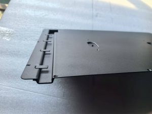
Bien que le problème d'étanchéité immédiat ait été résolu, le problème fondamental des coûts de fabrication prohibitifs persistait. Refusant de nous contenter de cette situation, notre équipe a mené une réflexion interne approfondie et a maintenu une communication étroite avec le client. Nous avons proposé une solution novatrice : remplacer l'assemblage soudé par un composant monobloc formé par estampage et emboutissage profond. Cette approche promettait de :
- Éliminer la cause première des défaillances d'étanchéité inhérentes au soudage.
- Réalisez des économies significatives en rationalisant la production.
- Améliorer la compétitivité du marché** pour le produit final du client.
Briser l'« impossible » :
Le client a révélé avoir déjà envisagé l'emboutissage, mais d'autres fournisseurs l'avaient jugé irréalisable pour cette pièce. Convaincus que « la preuve réside dans la pratique », nous avons mis à profit notre expertise technique pour proposer des optimisations de conception cruciales :
- 1. Ajuster l'angle de tirage pour améliorer le flux de matière.
- 2Spécifier un acier laminé à froid de qualité supérieure avec des propriétés d'emboutissage profond supérieures.
Le résultat positif :
Après un prototypage rigoureux et des tests de validation basés sur notre conception optimisée, nous avons livré le composant final. Les résultats ont été exceptionnels, en parfaite adéquation avec les intentions de conception et les exigences de performance du client. Ce dernier a exprimé sa profonde satisfaction et a fait l'éloge du produit : « C'est exactement le produit que j'avais imaginé ! » Il a remercié ChuangKai d'avoir résolu son problème technique persistant. Nous avons permis au client de respecter ses délais critiques tout en surmontant les problèmes de qualité et de coût, renforçant ainsi considérablement la compétitivité de ses produits sur le marché.
Étude de cas sur les améliorations apportées à la rupture des arbres de transmission des machines agricoles
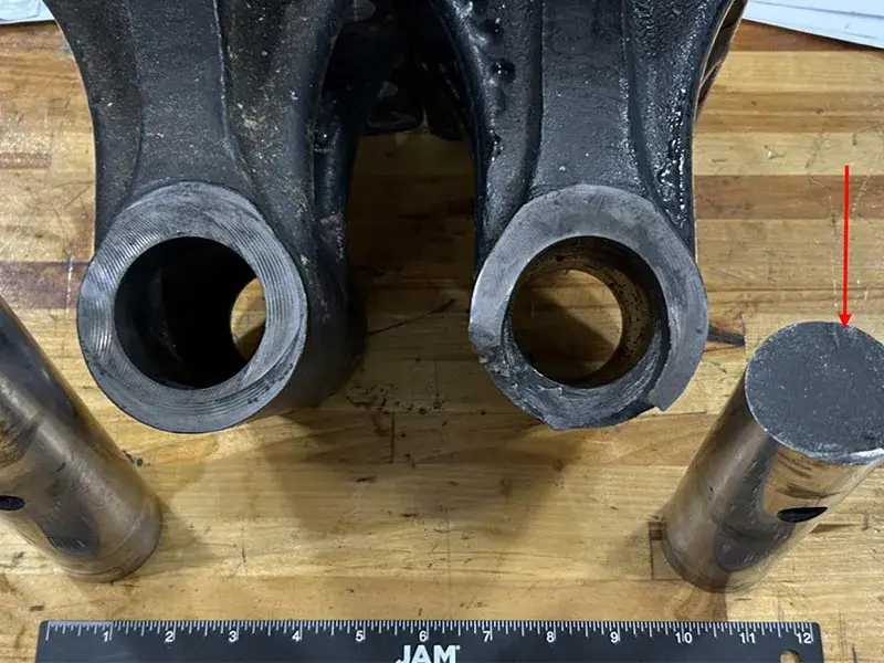
En juillet 2024, un client a signalé que l'axe de sa moissonneuse-batteuse s'était rompu lors d'une opération aux champs. Les clients finaux étaient très inquiets, car la récolte des céréales mûres ne pouvait se faire correctement. Ils ont d'abord pensé que la cause pouvait être la qualité de l'acier de l'arbre (40CrNiMoA) ou le traitement thermique. Nous avons reçu leur aide. L'axe cassé a été analysé une première fois et il a été conclu qu'il ne s'agissait pas d'un problème de matières premières ni de processus, mais d'un problème de conception du client. La saisonnalité n'est pas prise en compte. Les conditions de travail complexes de l'équipement et la fatigue unidirectionnelle présentent des dangers cachés. Les exigences du client concernant le traitement thermique global à haute dureté entraînent une dureté élevée du noyau, ce qui facilite la rupture par fatigue. Après analyse, nous avons suggéré d'adopter un processus de trempe par induction global, remplaçant le traitement thermique initial. Ce processus à haute dureté globale réduit la dureté du noyau et augmente la dureté de la surface extérieure, répondant ainsi aux exigences de résistance à l'usure. Nous avons ensuite envoyé le produit au client conformément au processus suggéré. Le nouvel échantillon a obtenu d'excellents résultats lors du deuxième essai sur le terrain. Les retours sont positifs.
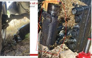
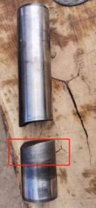
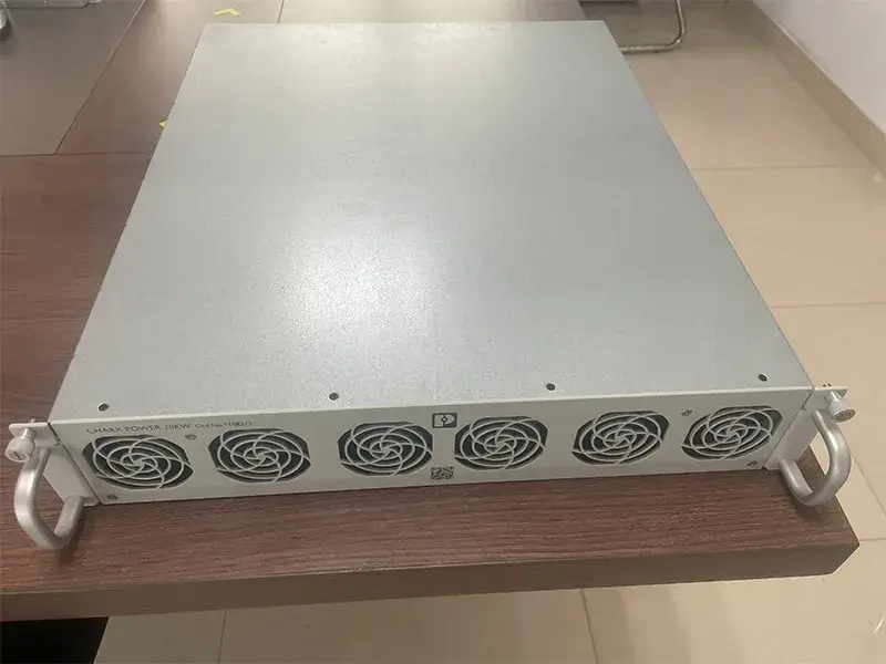
processus d'amélioration du boîtier d'alimentation
Un client allemand de notre entreprise rencontrait des difficultés de conception pour un coffret. L'utilisation de rivets entraînerait un dépassement du plan, affectant ainsi son fonctionnement. Quant au soudage, il ne répondrait pas aux exigences esthétiques et engendrerait un coût élevé. Après nous avoir contactés, nous avons constaté que nous avions déjà réalisé avec succès des projets similaires. Nous avons pu résoudre efficacement les problèmes de nos clients grâce à l'utilisation de rivets à double tête plate et de trous de fixation. Nous leur avons envoyé des échantillons.
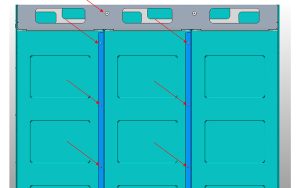
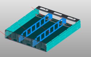
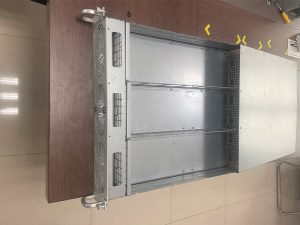
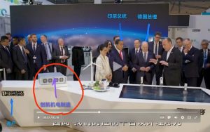
Ils étaient très satisfaits et ont obtenu d'excellents résultats à l'exposition de Hanovre. Ils ont reçu des éloges unanimes !

Votre partenaire pour des solutions de fabrication de bout en bout
Votre partenaire pour des solutions de fabrication de bout en bout
De la conception à la réalisation – Une ingénierie de précision pour un succès mondial
Chez ChuangKai, nous simplifions l'approvisionnement auprès de plusieurs fournisseurs. Fabricant verticalement intégré et spécialisé dans les solutions ODM et OEM, nous assurons une production fluide de composants de haute précision grâce à nos capacités étendues :
Services de fabrication intégrés :
- Usinage : Fraisage/Tournage CNC, Usinage suisse
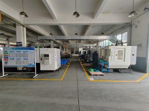
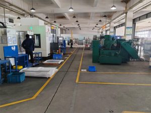
- Fabrication métallique : découpe laser, pliage, soudage
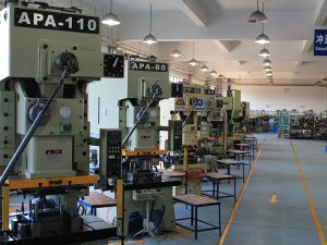
- Estampage et formage : Estampage progressif, emboutissage profond
- Outillage et moulage : Conception et fabrication de moules sur mesure
- Traitement de surface : revêtement en poudre, peinture au pistolet
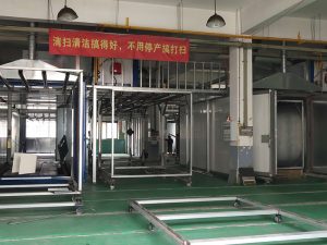
- Assemblage et tests : Kit complet, validation de la qualité
Avantages ODM/OEM pour votre entreprise :
Innovation en matière de design
Notre équipe d'ingénieurs collabore avec vous pour optimiser les conceptions en termes de fabricabilité, de rentabilité et de performance, transformant ainsi les concepts en produits prêts à être commercialisés.
Responsabilité à source unique
Plus besoin de coordonner plus de 5 fournisseurs. Nous gérons l'intégralité du flux de travail au sein d'une seule et même structure :
Conception → Prototypage → Outillage → Approvisionnement en matières premières → Production → Finition → Assemblage → Logistique
Production économique
Intégration verticale + optimisation des processus = réduction des coûts de 15 à 30 % par rapport aux chaînes d'approvisionnement fragmentées.
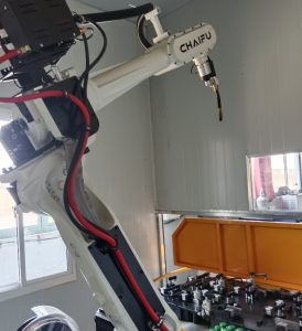
| Rapidité de mise sur le marché |
L'ingénierie simultanée réduit les délais de 40 %. Respectez les échéances sans compromettre la qualité.
| Qualité intégrée |
Processus certifiés ISO avec traçabilité numérique. Rapports PPAP, FAIR et CPK disponibles.
√ Secteurs d'activité que nous desservons :
Automobile | Machines industrielles | Dispositifs médicaux | Énergies renouvelables | Robotique | Production d'électricité nucléaire
Pourquoi nos clients internationaux nous choisissent :
Solutions aux problèmes : comme le [cas d'équipement de démonstration pédagogique] où nous avons remplacé les assemblages soudés par des pièces estampées intégrées – résolvant les fuites + réduisant les coûts de 25 %.
Capacité évolutive : prise en charge des prototypes NPI jusqu’aux séries de production de plus d’un million d’unités.
Agilité technique : Plus de 20 ingénieurs prêts à relever les défis complexes liés à la GD&T, aux tolérances serrées (±0,01 mm) et aux matériaux.
→ Demandez une analyse DFM gratuite
Téléchargez vos dessins/échantillons. Nos ingénieurs identifieront les optimisations de coûts et d'efficacité sous 48 heures.
Produits
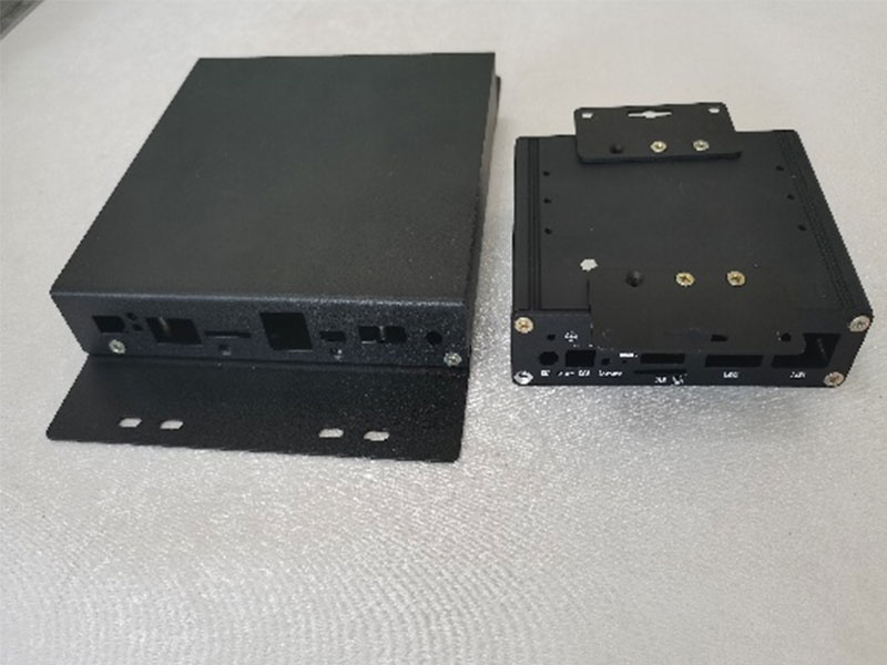
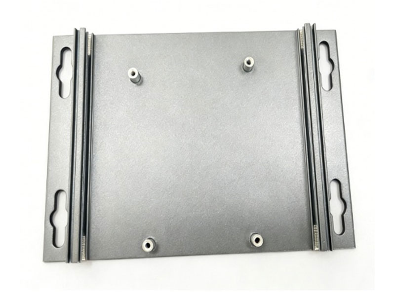

FAQ
Cette section répond aux questions fréquentes concernant nos produits, services et politiques mécaniques et électriques. Elle vous permet de trouver rapidement les informations dont vous avez besoin sans contacter le service d'assistance.
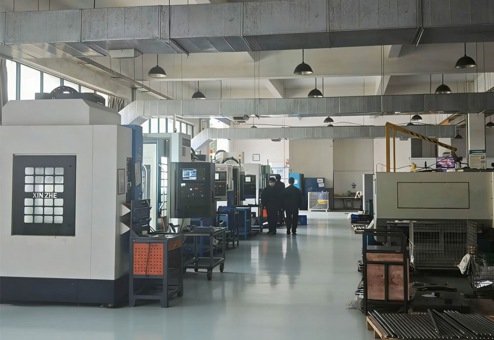
Notre force réside dans l'intégration de l'ensemble de la chaîne industrielle, depuis l'usinage de précision et le traitement de tôlerie de précision, la production par emboutissage, la conception et la fabrication à façon, le traitement de surface professionnel par pulvérisation jusqu'à l'assemblage final du produit, et la mise en œuvre d'un système de gestion de la qualité exceptionnel tout au long du processus. Ainsi, nos clients n'ont plus besoin de coordonner plusieurs fournisseurs pour bénéficier de services efficaces, coordonnés et constants. Notre contrôle qualité rigoureux est appliqué à chaque étape, garantissant que les pièces et produits livrés répondent non seulement aux exigences, mais constituent également des solutions globales stables, fiables et performantes, permettant à nos clients de réduire leurs délais de livraison et leurs coûts, et d'optimiser leur chaîne d'approvisionnement.
Traitement sur mesure des composants non standard. Ce délai dépend de la complexité du produit. Le délai de livraison est généralement de 2 à 4 semaines.
25
Années d'expérience
















Contactez-nous
articles récents
articles récents
Besoin de solutions mécaniques et électriques ou de questions ? Contactez-nous !
Tapping vs. Thread Milling for CNC-Machined OEM Parts: Choosing the Right Internal Thread Process
23
octobre
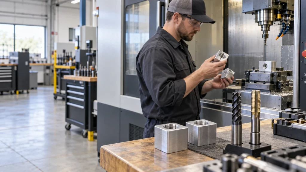
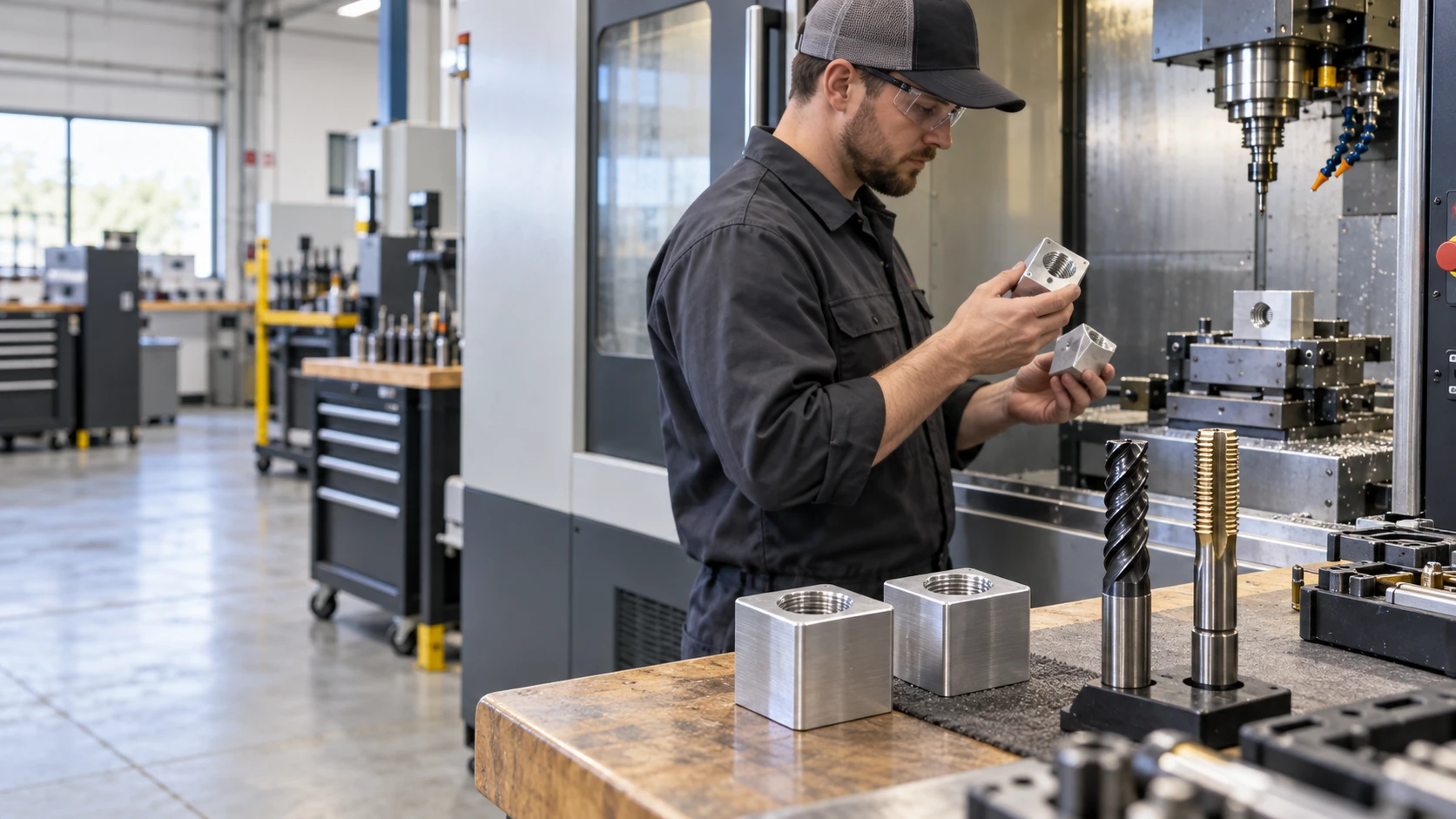
The choice between tapping and thread milling depends on the hole, material, thread specification, production quantity, machine capability, and cost of failure. Tapping is usually the faster route for repeat production of standard internal threads. Thread milling offers more control over thread size and fit, handles a wider range of diameters with fewer tools, and can reduce the consequence of a tool failure in a valuable part.
Neither process is universally better. A through-hole in a stable aluminum part may favor tapping, while a large thread, difficult material, expensive near-finished component, or close fit adjustment may justify thread milling. Blind-hole geometry and usable thread depth can change the answer again.
Tapping vs Thread Milling at a Glance
| Decision factor | Tapping | Thread milling |
| Cycle time | Often faster for standard repeated threads. | Usually longer because the tool follows a helical path. |
| Tool flexibility | One tap normally matches a specific size, pitch, and form. | One cutter may cover multiple diameters that share a compatible pitch and profile. |
| Fit adjustment | Limited after the tap and hole preparation are selected. | Tool-path offsets can adjust the finished thread within process limits. |
| Failure risk | A broken tap may be difficult to remove from the part. | A smaller cutter may be easier to recover from, but breakage can still damage the feature. |
| Machine need | Requires controlled feed and rotation appropriate to the tapping method. | Requires CNC helical interpolation, suitable control, rigidity, and access. |
How Each Process Cuts an Internal Thread
Both methods begin with a prepared hole, but their tool engagement is different. The drawing must specify the finished thread; the process planner then selects the pre-hole, tool, cutting data, and inspection route.
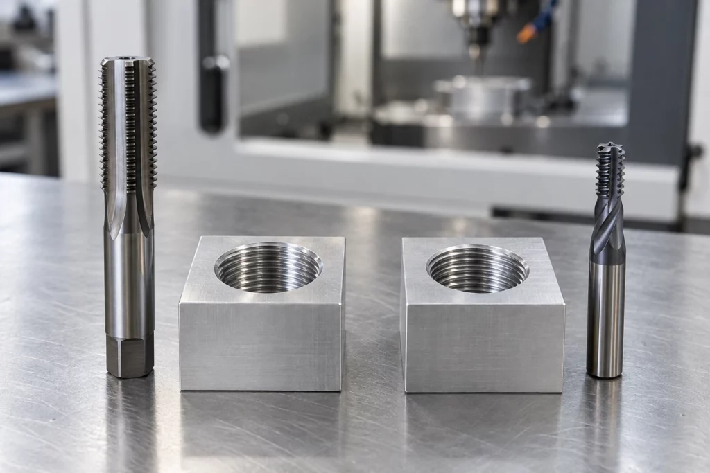
Tapping
A tap advances axially while its cutting edges or forming lobes create the complete thread profile. Because the tool engages around the circumference, torque, alignment, lubrication, chip control, and the prepared-hole diameter are important. Cut taps generate chips. Form taps displace suitable ductile material without chips, but they require a different hole size and should be approved for the material and specification.
Thread Milling
A thread mill rotates while the CNC moves it along a helical path. The cutter is smaller than the finished thread, so it engages a portion of the circumference at a time. The program controls diameter and direction, and suitable cutters can produce internal or external threads. The method needs enough bore access, tool clearance, machine interpolation, and stable workholding.
Choose by Hole Geometry
Through Holes
Through holes usually provide easier chip evacuation and fewer bottom-clearance constraints. For standard sizes and meaningful batch quantities, tapping often provides the most efficient cycle. A spiral-point cutting tap may push chips ahead through the opening when the material and application permit. Thread milling remains useful for large diameters, adjustable fits, mixed thread sizes, or parts where tool-breakage recovery influences the risk calculation.
Blind Holes
Blind holes need separate values for drilled depth, full thread depth, usable engagement, and bottom clearance. A tap has an incomplete lead before it produces full threads, and chips must have somewhere to go. Tap style, coolant delivery, chip evacuation, and reversal therefore matter. Thread milling can approach a shoulder with controlled axial positioning, but it still needs entry and exit clearance and cannot create usable thread beyond its programmed geometry. Do not specify “thread to bottom” without defining a manufacturable termination.
Choose by Material and Thread Specification
Material behavior affects torque, chips, tool wear, heat, and edge quality. Standard threads in machinable aluminum may favor tapping for speed, although chip packing or built-up edge still needs control. Tough stainless steels, high-temperature alloys, or expensive heat-treated parts may make the lower engagement and recovery advantages of thread milling more attractive. The supplier should confirm the exact alloy, hardness, and hole depth before choosing the route.
Thread size and form matter as much as material. Small standard threads may suit tapping, while larger diameters, special profiles, right- and left-hand variants, or adjustable fit classes can favor thread milling. A thread mill is not universal: its diameter, pitch capability, length, cutting form, and reach must match the feature.
Choose by Quantity and Cost of Failure
For a stable high-volume job, the shorter cycle of tapping can outweigh its lower flexibility. For prototypes and mixed families, thread milling may reduce the number of dedicated tools and allow diameter correction through offsets. The value of the workpiece also matters. Breaking a tap in an almost-complete housing can cost more than the saved cycle time; however, thread milling adds programming time and may use a more expensive cutter. Compare total route cost, not tool price alone.
Define the Thread Correctly on the Drawing
A process comparison cannot correct an incomplete specification. Use the same feature-based discipline applied to CNC machining tolerances, and include the following information:
- Thread standard and designation, nominal size, pitch or threads per inch, internal class or tolerance, and right- or left-hand direction.
- Through or blind condition, drilled depth, full thread depth, minimum usable engagement, entrance chamfer, and any bottom-clearance limit.
- Material grade and condition, heat treatment, coating or plating, quantity, critical datum relationships, and mating-fastener information.
- Inspection method, gauge standard, sampling level, first-article record, and any functional assembly test.
A complete CNC machining RFQ checklist also keeps model, drawing, revision, finish, and inspection assumptions consistent across bidders.
Verify the Sample and Production Route
Inspect the pre-hole as well as the finished thread. Confirm location, diameter, depth, chamfer, burr condition, and cleanliness. Use the specified GO and NO-GO gauges or another agreed method, then test the real mating fastener when assembly behavior matters. Record tool offsets and wear limits for thread milling, or torque, tap life, and chip-control checks for tapping. A first article should also confirm that coating, plating, or heat treatment does not invalidate the final fit.
Evaluate Supplier Capability Against the Part
CK Metal Tech publishes precision machining capabilities that include CNC milling, drilling, tapping, and related inspection resources. Its broader CNC machining services for precision metal parts provide the context for OEM process planning. The project review should still confirm whether tapping, thread milling, or another threading method is available and appropriate for the specific size, material, depth, tolerance, quantity, and inspection plan.
Conclusion
Use tapping when a standard internal thread, suitable material, controlled hole, and repeat quantity make cycle time the priority. Consider thread milling when fit adjustment, large or varied sizes, difficult materials, blind-hole constraints, or the cost of a trapped broken tap changes the economics. The drawing and sample plan should make the choice verifiable rather than leaving it to habit.
FAQ
Is Thread Milling Always More Accurate Than Tapping
No. Either process can make acceptable threads when the machine, tool, hole preparation, setup, and inspection suit the requirement. Thread milling offers useful diameter adjustment, but it does not replace process control.
Which Process Is Better for Blind Holes
It depends on usable depth, bottom clearance, material, chip control, thread size, and quantity. A suitable tap can be efficient; thread milling can improve control where evacuation or failure consequences are difficult.
Can One Thread Mill Cut Several Thread Sizes
Sometimes. A cutter may cover multiple diameters with a compatible pitch and profile, within its diameter and reach limits. Confirm the tool manufacturer’s range and the required thread form.
How Should an Internal Thread Be Inspected
Use the drawing’s specified gauge or measurement method and sampling plan. GO and NO-GO gauges are common, but depth, location, surface condition, and functional assembly may also require verification.
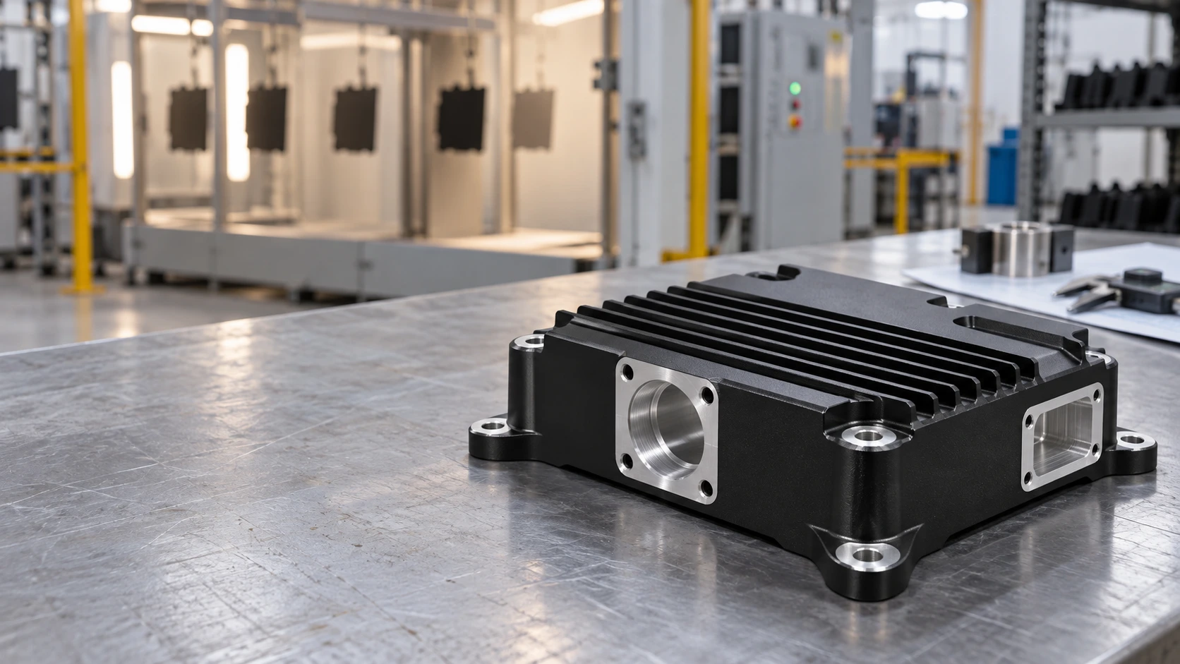
Can CNC-Machined Aluminum Housings Be Powder Coated? Thermal Interfaces, Fits, and Masking
22
octobre
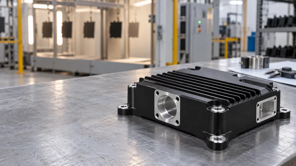
Can aluminum be powder coated after CNC machining? Yes, provided the drawing distinguishes cosmetic or protective surfaces from interfaces that must remain dimensionally, electrically, or thermally functional. A coating that performs well on an exterior wall can cause interference in a close fit, obstruct a thread, insulate a bonding point, or add thermal resistance at a heat-transfer joint.
The review should therefore start with the finished assembly, not the color. CK Metal Tech’s aluminum alloy cooling and shielding cover plate illustrates why this distinction matters: one machined component may combine an exterior cover, mounting holes, grooves, structural bosses, shielding functions, and heat-dissipation duties. Those surfaces should not automatically receive the same finish treatment.
Map Functional Surfaces Before Coating
Create a finish map on the controlled drawing or model. Identify coated faces, cosmetic faces, no-coat zones, and surfaces whose final dimensions apply after finishing. A generic note such as “powder coat black” does not tell the manufacturer how the housing must assemble or perform.
Surfaces Commonly Suitable for Coating
Exterior walls, non-mating covers, guards, and handling surfaces are typical candidates when the selected pretreatment and powder system match the aluminum alloy and service environment. Coating can support appearance and surface protection, but corrosion, chemical exposure, ultraviolet exposure, and cleaning requirements still need project-specific confirmation.
Surfaces That Often Need Masking
Common no-coat candidates include bearing or bushing seats, locating datums, close-tolerance bores, sliding rails, O-ring lands, sealing faces, connector grounds, threaded holes, fastener seats, and direct thermal contact pads. The decision is functional rather than categorical: a clearance hole may tolerate film build, while a locating hole with the same nominal diameter may not.
Mask Boundaries Need Their Own Definition
A no-coat note should show where the boundary begins, which direction the mask may shift, and whether a small transition band is acceptable. This is important around countersinks, spotfaces, grooves, stepped bores, gasket lands, and thermal pads. Masking has practical placement variation, and the cured edge may not form a perfectly sharp geometric line. Keep the boundary away from a sealing path or precision datum where possible. If the transition itself affects function, dimension it from a stable feature and include it in the first-article inspection plan.
How Powder Coat Changes Functional Interfaces
Powder coating adds material to the surfaces it covers. The actual build depends on the powder, application, grounding, part geometry, racking, and cure route, so the drawing should define the finished requirement instead of assuming a universal allowance.
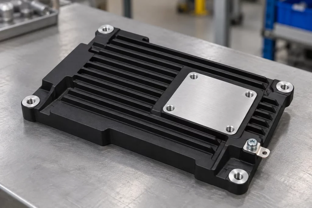
| Feature | Coating risk | Drawing or process control |
| Fits and threads | Film build reduces clearance and can obstruct engagement. | Mask, allow for the finish, or approve controlled post-coat machining. |
| Grounding points | The organic film can interrupt metal-to-metal electrical contact. | Mark bonding pads and define continuity or resistance verification. |
| Thermal interfaces | The coating and any trapped air can add resistance at a contact joint. | Keep direct-contact pads bare when required and define flatness, pressure, and interface material. |
| Sealing and datums | Build-up or an uneven mask edge can change seating and measurement references. | State whether dimensions apply before or after coating and locate mask boundaries. |
Fits and Threaded Features
Check each fit against its mating component and the finished-state tolerance. The same feature-level reasoning used for CNC machining tolerances applies after coating. Thread masks must protect the required diameter, lead-in, and usable depth. Forcing a screw through cured powder is not a controlled acceptance method because it can damage the finish and leave debris in the assembly.
Grounding and Thermal Contact
A designated grounding pad needs a clean boundary, a suitable fastener interface, and a defined verification method. Bare aluminum may also need a compatible protection strategy that preserves conductivity. For heat-transfer pads, evaluate coating together with contact area, surface flatness, clamping pressure, and any thermal interface material. A sample should be tested under representative heat load when temperature performance is critical.
Coordinate CNC Machining and Powder Coating as One Route
The safest sequence is established before chips are cut. Treat masking, finishing, and final inspection as part of the manufacturing plan rather than instructions added after machining.
- Review the current drawing, aluminum grade or approved alternative, functional interfaces, cosmetic zones, and operating environment.
- Machine the housing with any agreed allowance for surfaces controlled in the finished state; deburr edges without altering critical geometry.
- Clean and pretreat the part using a route compatible with the alloy, contamination condition, and specified coating system.
- Install plugs, caps, or high-temperature masking at the defined boundaries, then verify mask seating before spraying.
- Apply and cure the coating, remove masks cleanly, and inspect boundaries for lifting, chips, or unintended coverage.
- Complete only approved secondary machining or thread restoration, then clean the part and protect newly exposed aluminum as required.
An integrated review can connect the company’s precision machining capabilities with its powder coating service. The exact masking materials, post-coat operations, and inspection methods should still be confirmed for the part.
Verify the First Article Before Production
A first article should prove more than color and appearance. Use the actual mating components or representative gauges where possible, and record the drawing revision and coating specification used for approval.
- Dimensions: measure critical fits, datums, hole locations, and flatness in the state specified on the drawing.
- Assembly: install fasteners, covers, seals, rails, connectors, and locating features without forcing or finish damage.
- Electrical function: verify required bonding or shielding continuity at the specified contact points.
- Thermal function: check temperature performance under a representative load when the housing forms part of the heat path.
- Finish: inspect coverage, cure evidence, mask edges, handling damage, and cosmetic acceptance against an agreed reference.
Record nonconforming features separately. A part should not pass because its exterior looks uniform when a thread, bonding pad, thermal interface, or locating surface fails its own requirement.
What to Put in the Drawing and RFQ
Submit the 2D drawing and 3D model with material, quantity, coating system or performance requirement, color and texture, finished-state dimensions, no-coat zones, mask depth, thread callouts, grounding locations, thermal pads, inspection records, mating-part information, and sample approval criteria. Separate prototype quantity from expected production volume so the supplier can evaluate masking fixtures and process controls appropriately.
Conclusion
CNC-machined aluminum housings can be powder coated successfully when the finish map protects the part’s working interfaces. The design should preserve required clearance, thread engagement, electrical bonding, and thermal contact, while the process plan should connect machining, pretreatment, masking, coating, and finished-state inspection.
FAQ
Should Every Threaded Hole Be Masked
No. Masking depends on thread function, fastener fit, engagement depth, and the approved finishing route. The drawing should identify which threads must remain coating-free and how they will be checked.
Can Powder Coat Be Allowed for in a Close Fit
Sometimes, but the designer and manufacturer must agree on the final clearance and whether the controlling dimension applies before or after coating. Do not rely on a generic film allowance.
Should a Thermal Contact Pad Remain Bare
Often it should when direct metal contact is part of the heat path. Confirm the complete joint, including flatness, contact pressure, interface material, corrosion protection, and the required thermal test.
Is Post Coating Machining Acceptable
It may be, if the operation is planned. Control chips, protect the surrounding finish, re-inspect dimensions, and define how newly exposed aluminum will be handled.
Request a Joint Machining and Coating Review
Send CK Metal Tech the drawing revision, alloy, quantity, mating-part details, coating requirements, no-coat zones, thermal duty, grounding needs, and inspection expectations. Use the request a joint machining and coating review route to confirm the manufacturing sequence before quotation.
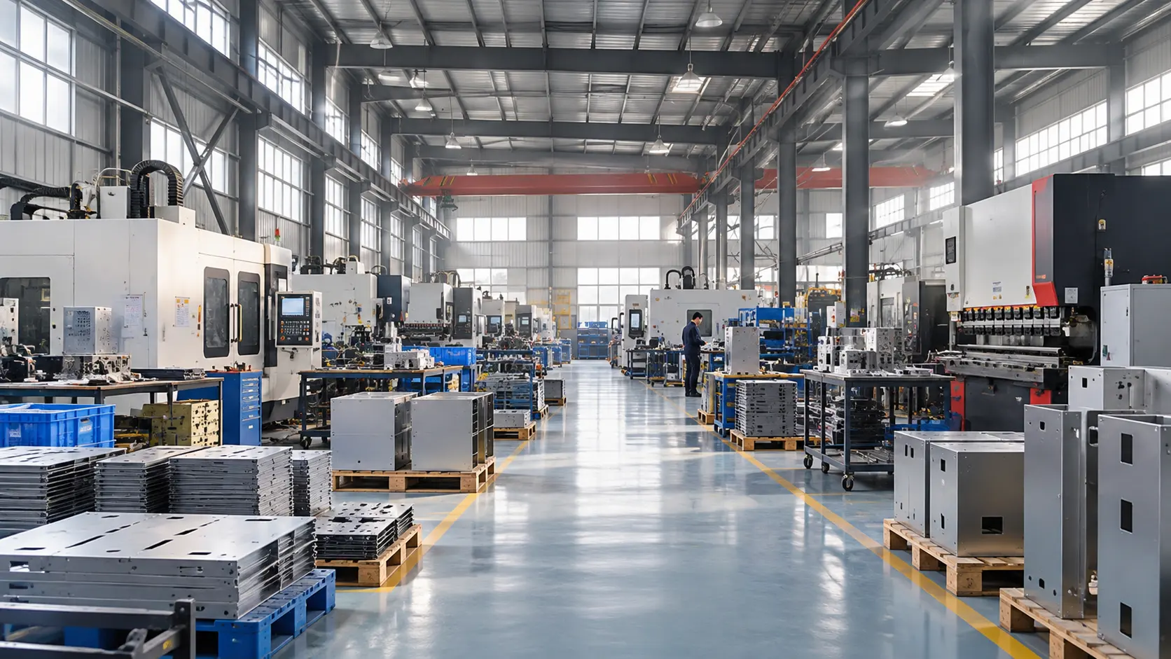
One Metal Supplier vs Multiple Vendors: How to Calculate Total Landed Cost
16
octobre
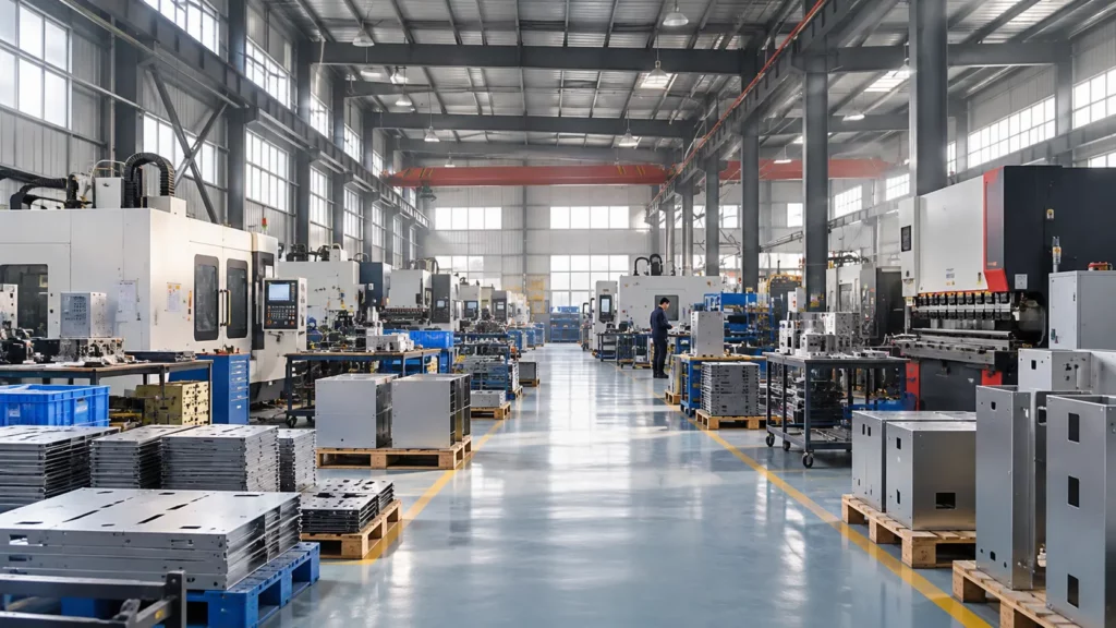
One metal supplier can reduce transfers between fabrication, finishing, and assembly, but supplier consolidation does not automatically lower total landed cost. Compare both routes at the same delivery destination, then add the buyer-side costs needed to turn delivered parts into accepted assemblies. Keep those layers separate: shipping and import charges belong in the landed-cost calculation; supplier administration, inventory, and integration costs belong in the broader sourcing decision.
For an OEM buying custom metal parts, this distinction prevents a lower piece price from hiding extra work. It also avoids calling every future operating expense a landed cost.
Define the Deliverable Before Comparing Vendors
Start with one controlled bill of materials and drawing revision. Specify material, finish, quantity, inspection criteria, packaging, destination, and assembly responsibility. A coated panel from one vendor cannot be compared directly with an assembled enclosure from another unless the missing operations are priced separately.
Distinguish process splitting from dual sourcing. Sending cutting to one shop and coating to another creates sequential handoffs. Qualifying two independent suppliers for the same finished assembly creates a backup route. These arrangements have different costs and continuity benefits; combining them under “multiple vendors” obscures the decision.
Calculate Total Landed Cost in Two Layers
The core shipment calculation is:
Landed cost = supplier invoices + separately charged tooling + packaging + freight + insurance + applicable duties, taxes, and clearance fees.
The International Trade Administration’s landed-cost guidance supports the product-plus-delivery approach. For metal parts, verify which charges are already included in each quotation. Add only costs outside the quoted scope, and use the same receiving location.
Then calculate a separate management metric:
Sourcing comparison cost = landed cost + buyer assembly and inspection + supplier administration + inventory carrying cost + evidence-based quality and disruption allowances.
This second formula is a purchasing decision tool, not a customs valuation or accounting rule. It does not include equipment operating costs over the product’s lifetime. Keep recoverable taxes and other accounting treatments identifiable for finance review rather than treating every cash payment as a permanent expense.
Normalize Quotes and Allocate Shared Charges
Use the same currency, demand period, release size, and named delivery point. Record the delivery term and which party pays each freight leg. A quote that includes shipping can appear expensive beside a factory-gate quote until the missing freight is added.
For international purchases, ask a qualified broker to verify classification, origin, applicable charges, and the relevant shipment date. Do not copy a tariff percentage from another part or last year’s order.
Allocate shared freight across a mixed shipment using a defensible driver, such as chargeable weight or occupied volume. Allocate tooling over the realistically committed program quantity, with tooling ownership shown separately. Show first-order and repeat-order costs independently; an optimistic lifetime volume can conceal a costly launch.
A Worked Example for One Thousand Assemblies
The following figures are hypothetical USD amounts, not CK Metal Tech quotations or tariff estimates. Both routes ultimately provide 1,000 accepted assemblies. The single supplier includes assembly in its invoice; the split route requires more buyer assembly work. Charges already included in supplier invoices are excluded from the other rows.
| Cost category | One supplier | Multiple vendors |
| Supplier invoices | $40,000 | $37,000 |
| Tooling and setup | $3,000 | $2,200 |
| Packaging freight and insurance | $1,800 | $3,300 |
| Illustrative import and clearance charges | $1,500 | $1,500 |
| Core landed cost | $46,300 | $44,000 |
| Buyer assembly and inspection | $800 | $3,300 |
| Supplier administration | $400 | $1,200 |
| Inventory carrying cost | $600 | $1,100 |
| Expected quality and rework allowance | $600 | $1,800 |
| Sourcing comparison total | $48,700 | $51,400 |
| Cost per accepted assembly | $48.70 | $51.40 |
Multiple vendors win the core landed-cost comparison by $2,300. After buyer-side costs are included, one supplier is lower by $2,700. This result follows the stated assumptions; it does not prove that consolidation is generally cheaper.
The decision changes if the split route reduces internal assembly effort, avoids quality losses, or provides a valuable qualified backup. Replace every allowance with program evidence before using this example for an award decision.
Measure Handoffs Without Double Counting
Map the route from cutting and forming through machining, coating, final inspection, and packing. Sheet metal fabrication may involve several linked operations, so track the transfers between them rather than counting suppliers alone.
For each handoff, record transport, protective packaging, receiving inspection, queue time, and revision-control responsibility. Estimate internal work from hours multiplied by an approved labor rate. Distinguish cash savings from staff capacity released: fewer purchase orders do not necessarily reduce payroll.
Estimate inventory carrying cost from average inventory value, the approved annual carrying rate, and the time period. Use historical rework and expedite costs where available. For a new program, show low, expected, and high cases rather than inventing a precise failure probability.
Avoid charging the same loss twice. If rejected units already reduce the accepted-unit denominator, check whether a separate scrap allowance repeats that loss. Likewise, do not add replacement freight when it is already included in a rework estimate.
Choose the Route and Test Its Weak Points
One supplier is attractive when interfaces dominate the program: welded frames must match machined brackets, coating boundaries affect fit, and completed assemblies require a coordinated release. Multiple vendors may be preferable when a process needs specialist qualification, capacity is constrained, or a genuinely independent backup is essential.
A backup is only useful if drawings, tooling access, qualification status, and available capacity make it executable. Two suppliers sharing the same critical subcontractor may still have a common interruption risk. Keep continuity requirements visible beside the cost comparison.
Test the decision against smaller releases, a rejected batch, an engineering change, and an expedited shipment. If the winner changes under a small assumption adjustment, resolve that uncertainty before committing the production route.
Request a Comparable Metal Manufacturing Quote
CK Metal Tech combines sheet metal processing, machining, stamping, powder coating, painting, and precision-component assembly. Review its metal manufacturing and assembly capabilities against the proposed route; process breadth alone does not establish capacity or suitability for a particular program.
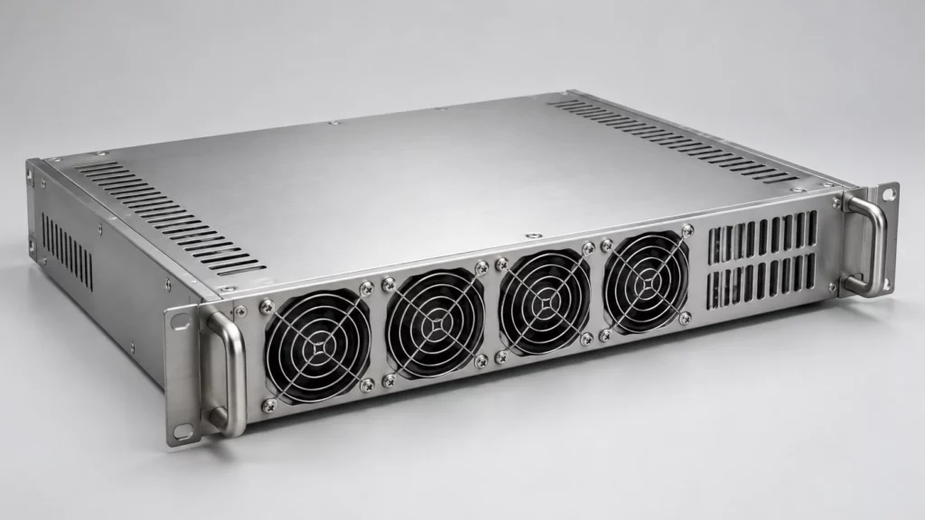
Send the BOM, controlled drawings, quantities, destination, finish requirements, and acceptance plan. Ask CK Metal Tech to separate tooling from recurring prices and identify subcontracted operations, excluded services, and packing assumptions. Give alternative vendors the same package.
Conclusion
Choose the sourcing route using both delivered cost and the work required to obtain accepted assemblies. A transparent comparison can show that multiple vendors win on landed cost while one supplier wins after integration costs, or the reverse. Award the route whose cost assumptions and continuity requirements can be verified.
FAQ
Is one metal supplier always cheaper
No. Consolidation may reduce transfers and administration, while multiple vendors can provide specialist capability or backup capacity. Compare equivalent outputs and documented costs.
Is total landed cost the same as total cost of ownership
No. Landed cost addresses acquisition and delivery. Ownership cost extends into use, maintenance, and disposal. Buyer integration costs should remain a clearly labeled comparison layer.
How should tooling be included
Show the initial tooling payment separately, then allocate it across a defensible committed quantity for the unit comparison. Record ownership, maintenance responsibility, and repeat-order assumptions.
Should supplier management time count as a saving
Include it when comparing resource demand, but distinguish released staff capacity from actual cash savings. Use measured hours and an approved rate.
Request a Sourcing Route Review
Share the current drawings, BOM, delivery location, release schedule, and assembly scope with CK Metal Tech. Request a sourcing-route review to clarify included operations and compare the assumptions behind each quotation.