







-
Fabricação de protótipos acelerada em 1 a 3 dias e cadeia de suprimentos flexível e ágil.
-
Compromisso firme com a entrega pontual e qualidade premium consistente do produto.
-
Ampla gama de opções de materiais + tratamentos de acabamento de superfície padrão da indústria.
-
Cotação direta da fábrica e detalhamento de custos totalmente transparente.
-
Sistema de qualidade certificado segundo as normas ISO 9001:2015 / IATF 16949:2016
-
Serviço de montagem integrado chave na mão: Fornecemos produtos acabados e prontos para uso, além de peças de reposição avulsas.
Serviço completo de metalurgia personalizada, da prototipagem à produção em massa.
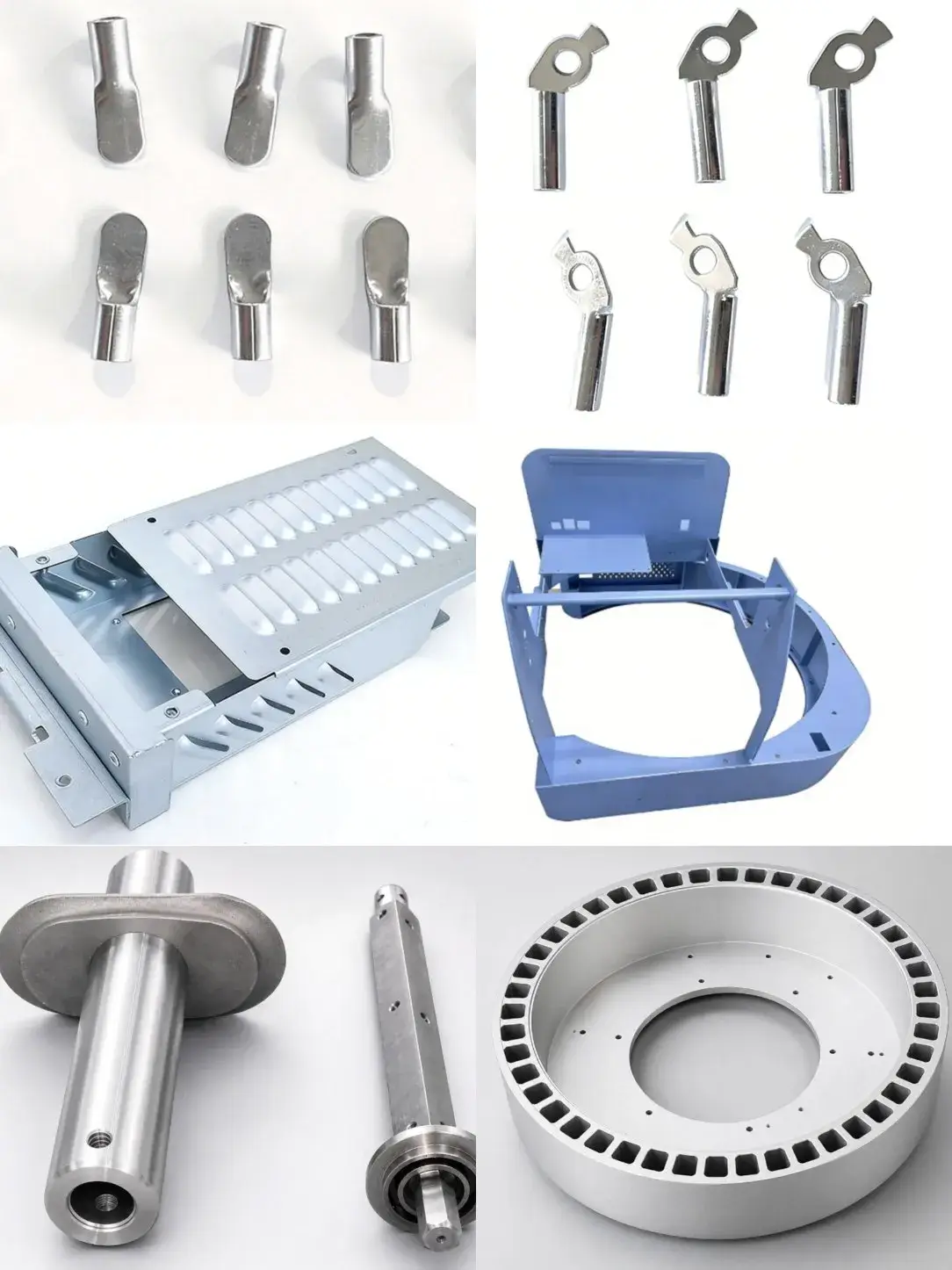
Apoiar diversas aplicações de engenharia e fabricação.
-
Preços competitivos e DFM (Design for Manufacturing)
-
Suporte de engenharia 24 horas por dia, 7 dias por semana
-
Entrega rápida, prazo de produção curto, sem quantidade mínima de pedido.
Verifique as certificações sob demanda: ISO 9001:2015 | IATF 16949:2016

sobre chuangkai
A Zhejiang Chuangkai Mechanical and Electrical Technology Co., Ltd. foi fundada em março de 2003, com um capital social de 15 milhões de RMB. A empresa é uma empresa de alta tecnologia que integra o projeto e a fabricação de ferramentas de precisão, estampagem de metais de precisão, processamento de chapas metálicas de precisão, usinagem de precisão, pintura de superfície, revestimento em pó e montagem de componentes de precisão. Atualmente, conta com 95 funcionários e possui equipamentos avançados de processamento de precisão e oficinas padronizadas, com uma área total de aproximadamente 13.500 metros quadrados. Obtivemos as certificações ISO9001, IATF16949, ISO45001 e ISO14001.

Projeto e fabricação de ferramentas de estampagem de precisão

Principais equipamentos de estampagem na oficina de estampagem: 18 conjuntos de prensas de puncionamento de alta velocidade e precisão com especificações de 16 toneladas, 25 toneladas, 40 toneladas, 60 toneladas, 80 toneladas, 110 toneladas, 200 toneladas e 250 toneladas. A velocidade das prensas de puncionamento de alta precisão pode atingir 500 vezes por minuto.
Materiais para processos de estampagem: latão, bronze fosforoso, bronze berílio, cobre branco níquel, bem como vários tipos de aço e aço inoxidável, tiras de níquel, aço laminado a frio, tiras de aço (incluindo pré-revestidas), chapas galvanizadas, aço de baixo carbono, aço mola e outros materiais compostos.
Fabricação de chapas metálicas de precisão
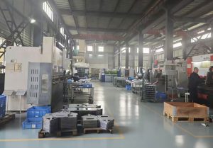
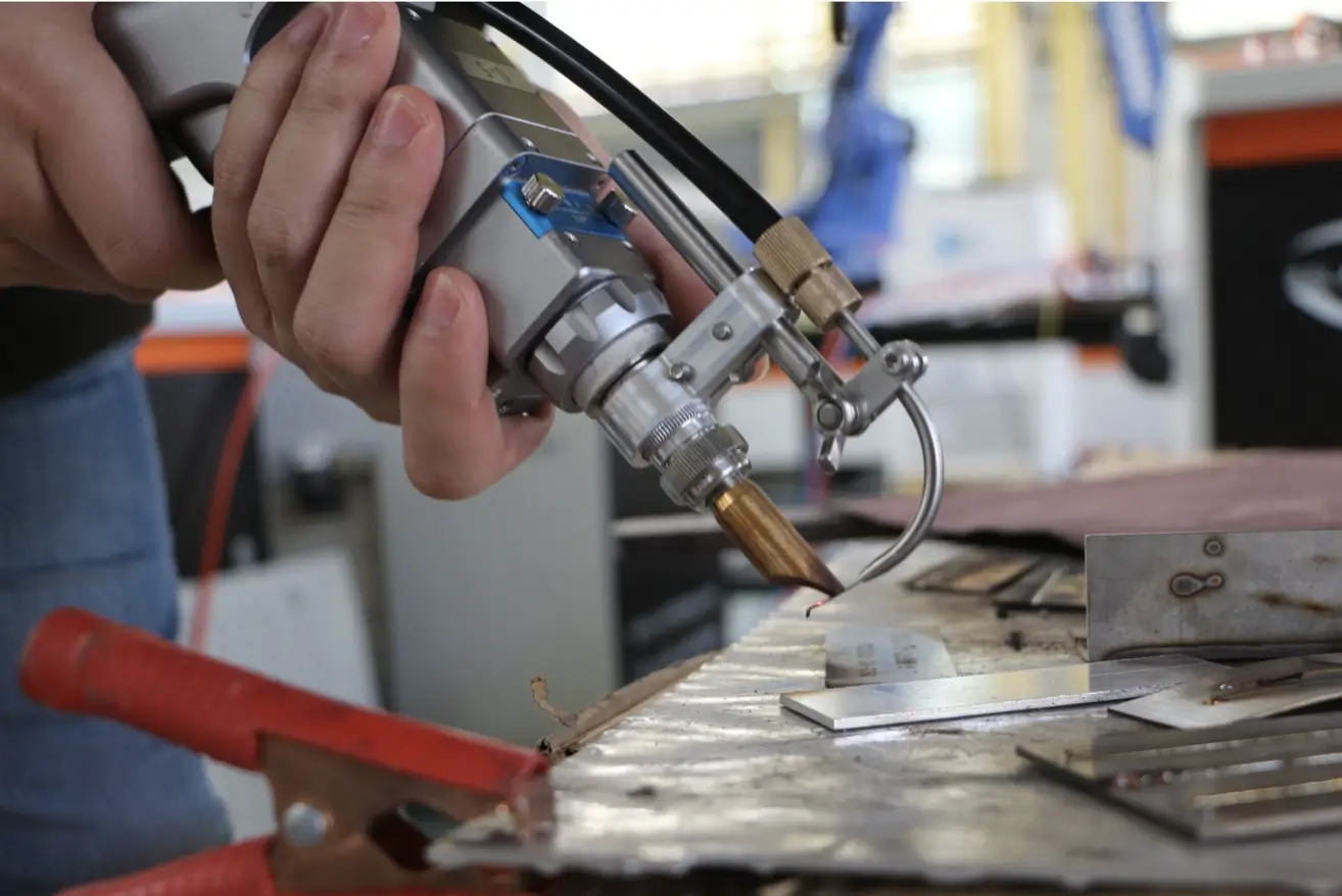
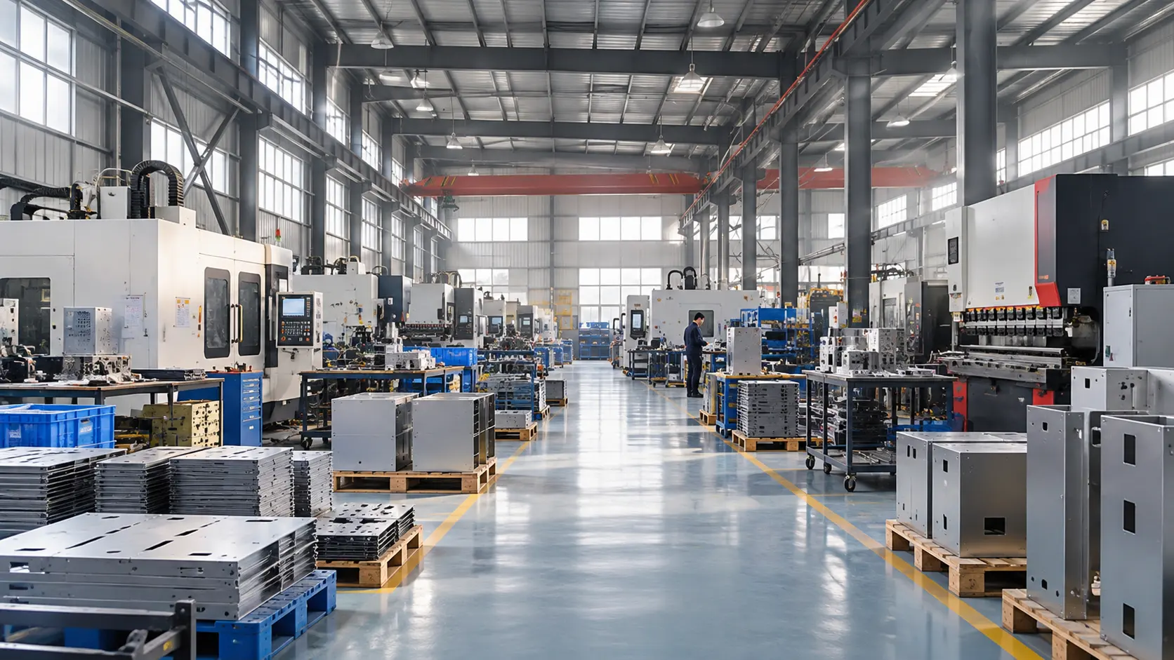
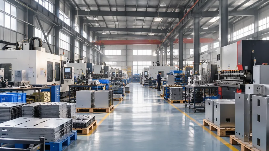
A oficina de chapas metálicas está equipada com equipamentos de processamento de chapas metálicas de precisão, incluindo 2 máquinas de corte a laser CNC avançadas de grande escala, 1 prensa de puncionamento CNC, 5 máquinas de dobra CNC, bem como máquinas de rebitagem, máquinas de solda, retificadoras, máquinas de trefilação e outros equipamentos.
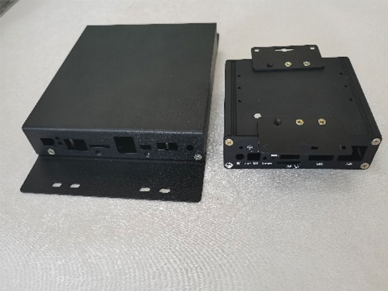
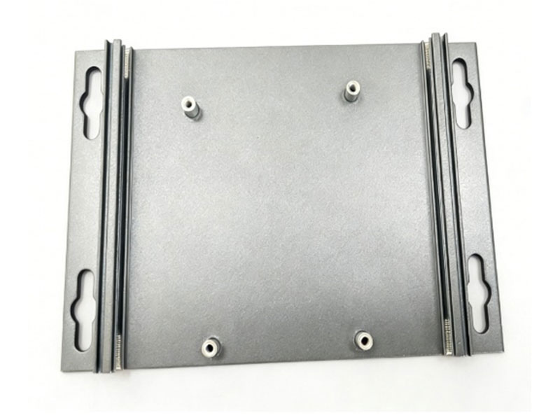
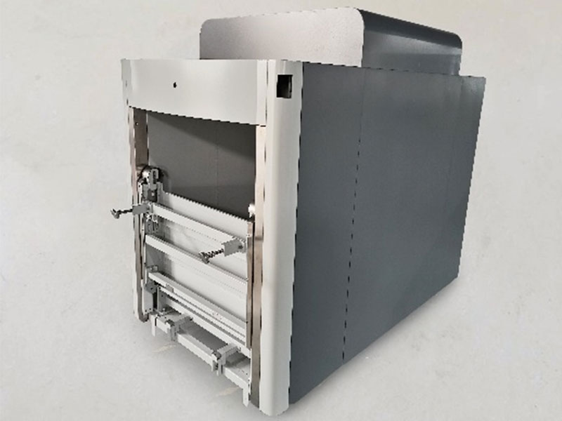
Os produtos processados abrangem automação industrial, equipamentos médicos, equipamentos elétricos, caixas elétricas, caixas de junção elétrica e outras áreas. A empresa realiza processamento de precisão, como corte rápido e processamento de chapas metálicas nos seguintes materiais: aço inoxidável, aço carbono, aço silício, liga de alumínio, chapa galvanizada, chapa de alumínio-zinco, etc.
Revestimento em pó e pintura
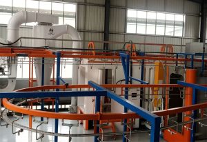
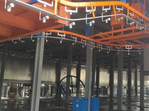
Uma linha automática de pintura a pó;
Uma linha manual de pintura a pó (para peças grandes e caixas grandes);
Uma linha de pintura manual (para peças grandes e caixas grandes);
Uma linha híbrida automática de pintura e revestimento em pó está em construção.
Usinagem de precisão

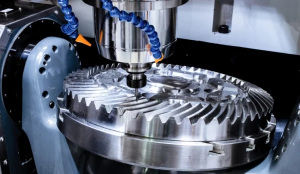
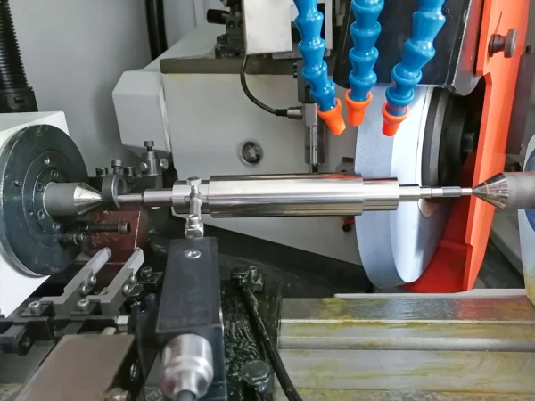
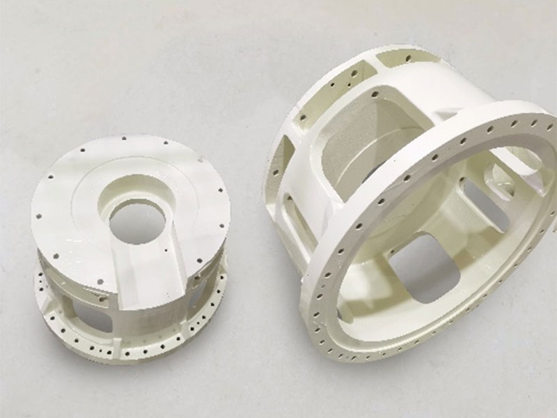
A oficina de usinagem está equipada com equipamentos de precisão, incluindo 6 conjuntos de máquinas CNC de 4 eixos, 1 conjunto de torno tipo suíço de 5 eixos, 13 conjuntos de tornos CNC de precisão, 4 conjuntos de fresadoras CNC, 16 conjuntos de tornos automáticos de precisão Mingyang de Taiwan, bem como tornos comuns de precisão, fresadoras de precisão de 3 eixos com display digital, tornos de bancada de precisão, fresadoras de borda automáticas Jizuan de Taiwan, máquinas de laminação de roscas de precisão, matrizes de laminação de roscas, máquinas de rosqueamento de precisão, furadeiras de precisão, fresadoras de precisão com display digital de Taiwan, afiadores de facas de precisão, retificadoras cilíndricas internas e externas, retificadoras sem centros, serras, máquinas de limpeza e secagem ultrassônicas, máquinas de polimento, soldadores elétricos, soldadores a arco e outros equipamentos.
nosso
Vídeo de introdução
nossas curiosidades
Chega de coordenar mais de 5 fornecedores. Produção com custo inteligente: Integração vertical + otimização de processos = redução de custos de 15 a 30% em comparação com cadeias de suprimentos fragmentadas.
Agilidade no lançamento do produto: A engenharia simultânea reduz os prazos de entrega em 40%. Cumpra os prazos sem comprometer a qualidade.
Solicite uma Análise DFM gratuita: Envie seus desenhos/amostras. Nossos engenheiros identificarão otimizações de custo e eficiência em até 48 horas.

a empresa é construída
0
capital registrado
0M
funcionários
0+
área da fábrica
0+
nosso caso
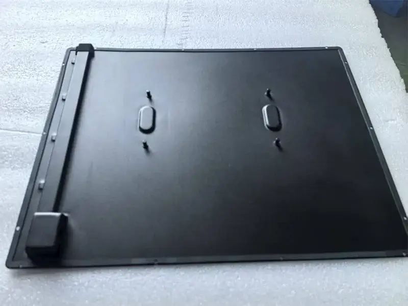
Utilize o processo de estiramento como substituto da tecnologia de solda + polimento + raspagem com massa.
Utilize o processo de estiramento como substituto para soldagem e polimento. +Raspe a massa Tecnologia
Supere o gargalo técnico e crie peças estruturais metálicas de alta qualidade e com preço acessível para equipamentos de demonstração didática:
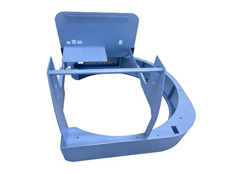
Quando um cliente estava desenvolvendo um computador de demonstração de grande porte para treinamento e ensino, suas principais peças estruturais metálicas enfrentaram sérios desafios. O projeto inicial da peça utilizava soldagem para fabricar a parte saliente, mas, na fase de testes do produto, a baixa resistência da solda impediu que o produto passasse nos testes críticos. Ao mesmo tempo, o alto custo do processo de soldagem elevava significativamente o preço das peças em comparação com a concorrência, o prazo de entrega do projeto era iminente e o cliente enfrentava grande pressão em relação à qualidade e ao custo.
Identifique com precisão os pontos problemáticos e responda rapidamente para resolvê-los:
Após entendermos a situação do cliente, rapidamente formamos uma equipe técnica especializada. No primeiro seminário técnico, analisamos a fundo a causa raiz da baixa estanqueidade da soldagem. Embora tenhamos conseguido resolver o problema da estanqueidade e atender aos requisitos iniciais de qualidade do cliente com a otimização dos parâmetros de soldagem e a introdução de novas máquinas e operadores. No entanto, o problema do alto custo da soldagem ainda persiste.
Plano inovador, de duas frentes:
A equipe técnica não parou por aí. Após várias rodadas de discussões internas e comunicação constante com os clientes, propusemos uma solução fundamental: substituir a soldagem original por um processo integrado de estampagem e estiramento + polimento + raspagem. Isso não só elimina completamente o risco de falhas na soldagem desde a origem, como também reduz significativamente o custo de produção e possibilita que o produto conquiste uma fatia maior do mercado.
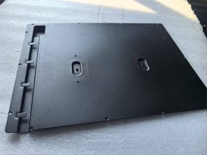
Agarre o impossível, cumpra a promessa:
O feedback dos clientes considerou a possibilidade de personalização. O plano de personalização, no entanto, foi questionado por outros fornecedores, que afirmaram ser inviável. Diante das dúvidas, acreditamos firmemente que "aprende-se fazendo". Com base em nossa vasta experiência tecnológica, oferecemos aos clientes sugestões essenciais de otimização, incluindo:
Ajuste o ângulo de inclinação da tração para otimizar a fluidez do material e escolha uma marca específica de chapa de aço laminada a frio com melhor desempenho de tração.
Excelentes resultados, elogiados pelos clientes:
Após a definição do plano, realizamos diversas rodadas de testes de processo rigorosos e verificação de amostras. As peças finais entregues atendem perfeitamente aos requisitos de projeto e padrões de desempenho do cliente. O cliente ficou extremamente satisfeito com os resultados e não apenas elogiou o produto: "Este é o produto perfeito, exatamente como eu queria!", como também expressou sua sincera gratidão pela capacidade da equipe Chuangkai em superar desafios complexos. Conseguimos ajudar nossos clientes dentro do prazo de entrega urgente, solucionando problemas complexos de qualidade e custo, e contribuindo para que seus produtos obtivessem vantagem competitiva no mercado.
Superando obstáculos técnicos para fornecer componentes metálicos de alta qualidade e custo-benefício para sistemas e displays educacionais.
O desafio:
Um cliente que desenvolvia computadores de demonstração de grande porte para treinamento e educação enfrentou problemas críticos com um componente estrutural metálico fundamental. O projeto inicial utilizava saliências soldadas. No entanto, durante os testes do produto, a baixa integridade da vedação da solda causou falhas. Para agravar o problema, o alto custo do processo de soldagem tornou o componente significativamente mais caro do que o da concorrência. Com os prazos do projeto se aproximando, o cliente estava sob imensa pressão para resolver os desafios de qualidade e custo.
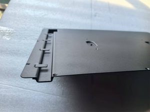
Nossa resposta rápida e solução inicial:
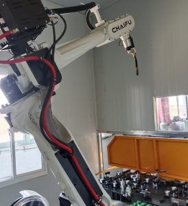
Ao tomarmos conhecimento do dilema do cliente, formamos imediatamente uma equipe técnica dedicada. Na análise técnica inicial, investigamos minuciosamente a causa raiz da falha de vedação. Através de extensos testes de otimização dos parâmetros de soldagem e da implementação estratégica da soldagem robótica, alcançamos com sucesso a integridade de vedação necessária, atendendo às especificações de qualidade do cliente.
Identificar a questão mais profunda e propor inovação:
Embora o problema imediato de vedação tivesse sido resolvido, o problema fundamental dos custos proibitivos de fabricação persistia. Recusando-nos a aceitar uma solução inconclusiva, nossa equipe de trabalho se dedicou a um intenso brainstorming interno e manteve comunicação constante com o cliente. Propusemos uma solução transformadora: substituir a montagem soldada por um componente monobloco formado por estampagem e embutimento profundo. Essa abordagem prometia:
- Elimine a causa principal das falhas de vedação inerentes à soldagem.
- Obtenha uma redução significativa de custos através da otimização da produção.
- Aumentar a competitividade de mercado** para o produto final do cliente.
Superando o "Impossível":
O cliente revelou que já havia explorado a estampagem, mas outros fornecedores a consideraram inviável para esta peça. Guiados pela nossa crença de que "a prova está na prática", aproveitamos nossa expertise técnica para propor otimizações de design cruciais:
- 1. Ajustar o ângulo de tração para melhorar o fluxo de material.
- 2. Especificar um aço laminado a frio de qualidade superior com propriedades de estampagem profunda excelentes.
O resultado bem-sucedido:
Após rigorosos testes de prototipagem e validação baseados em nosso projeto otimizado, entregamos o componente final. Os resultados foram excepcionais, alinhando-se perfeitamente com a intenção do projeto e os requisitos de desempenho do cliente. O cliente expressou profunda satisfação, tecendo grandes elogios: "Este é o produto perfeito que imaginei em meu projeto!". Eles agradeceram explicitamente à ChuangKai por resolver seu persistente problema técnico. Permitimos que o cliente cumprisse seu prazo crítico, superando simultaneamente o defeito de qualidade e a barreira de custo, aumentando significativamente a competitividade de seus produtos no mercado.
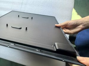
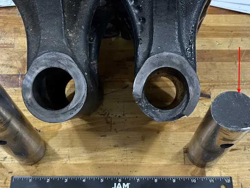
Estudo de caso sobre melhorias para evitar a quebra do eixo de máquinas agrícolas
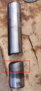
Em julho de 2024, um cliente relatou que o eixo de sua colheitadeira havia se rompido durante a operação no campo, e os clientes finais estavam muito preocupados com o fato de que os grãos maduros não poderiam ser colhidos adequadamente. Inicialmente, eles pensaram que poderia ser devido à matéria-prima do eixo (40CrNiMoA) ou ao processo de tratamento térmico que não atendia aos requisitos. Recebemos a ajuda deles. O eixo quebrado foi analisado inicialmente e concluiu-se que o problema não estava nas matérias-primas, mas sim no processo de fabricação. O projeto do cliente não levou em consideração as complexas condições de trabalho do equipamento, além dos riscos ocultos de fadiga por força unidirecional. O tratamento térmico de alta dureza, exigido pelo cliente, resulta em um núcleo altamente duro, o que facilita a quebra por desgaste. Após a análise, sugerimos a adoção de um processo de têmpera por indução, substituindo o tratamento térmico original. Esse processo reduz a dureza do núcleo e aumenta a dureza da superfície externa, atendendo aos requisitos de resistência ao desgaste. Enviamos a amostra ao cliente de acordo com o processo sugerido. A nova amostra obteve excelentes resultados no segundo teste de campo. O feedback tem sido muito positivo.
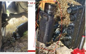
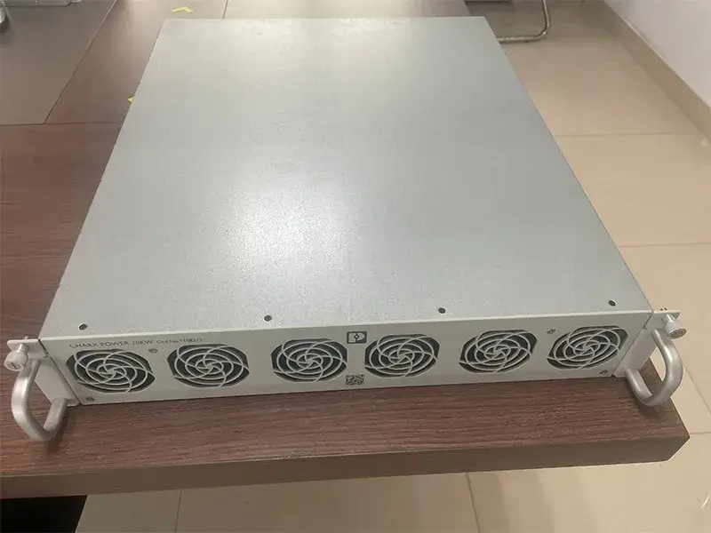
Processo de melhoria da caixa da fonte de alimentação
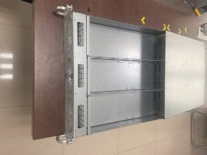
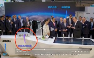
Um cliente alemão da nossa empresa tinha uma caixa de combinação que apresentava dificuldades na fase de projeto. Se o método de rebitagem fosse adotado, a peça ficaria saliente, afetando a funcionalidade. Se o método de soldagem fosse utilizado, a aparência não atenderia aos requisitos e o custo seria elevado. Após entrar em contato conosco, descobrimos que tínhamos casos de sucesso em outros projetos. Conseguimos resolver os problemas do cliente de forma muito eficaz utilizando rebites de cabeça chata dupla e furos de fixação. Enviamos amostras para o cliente.
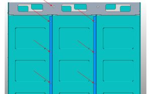
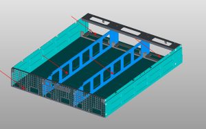
Eles ficaram muito satisfeitos e obtiveram excelentes resultados na exposição de Hanôver, recebendo elogios unânimes!

Seu parceiro para soluções de fabricação de ponta a ponta
Seu parceiro para soluções de fabricação de ponta a ponta
Do conceito à conclusão – Engenharia de precisão para o sucesso global.
Na ChuangKai, eliminamos as complexidades da terceirização com múltiplos fornecedores. Como fabricante verticalmente integrado, especializado em soluções ODM e OEM, oferecemos produção contínua de componentes de alta precisão por meio de nossas amplas capacidades:
Serviços Integrados de Manufatura:
- Usinagem: Fresamento/Torneamento CNC, Usinagem Suíça
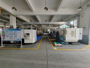
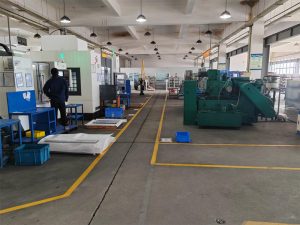
- Fabricação de metais: corte a laser, dobra, soldagem.
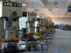
- Estampagem e Conformação: Estampagem Progressiva, Estampagem Profunda
- Ferramentas e Moldagem: Projeto e Fabricação de Matrizes/Moldes Personalizados
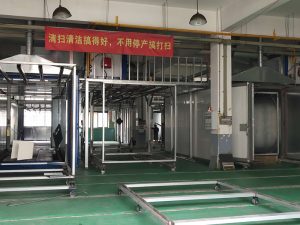
- Tratamento de superfície: Revestimento em pó, Pintura por pulverização
- Montagem e Testes: Kit completo, Validação de Qualidade
Vantagens de ODM/OEM para o seu negócio:
Inovação em Design
Nossa equipe de engenharia colabora com você para otimizar projetos em termos de fabricação, custo-benefício e desempenho, transformando conceitos em produtos prontos para o mercado.
Responsabilidade de fonte única
Chega de coordenar mais de 5 fornecedores. Gerenciamos todo o fluxo de trabalho em um só lugar:
Design → Prototipagem → Ferramentaria → Aquisição de Matéria-Prima → Produção → Acabamento → Montagem → Logística
Produção com custo-benefício
Integração vertical + otimização de processos = redução de custos de 15 a 30% em comparação com cadeias de suprimentos fragmentadas.
| Rapidez no lançamento do produto no mercado |
A engenharia simultânea reduz os prazos de entrega em 40%. Cumpra os prazos sem comprometer a qualidade.
| Qualidade Integrada |
Processos com certificação ISO e rastreabilidade digital. Relatórios PPAP, FAIR e CPK disponíveis.
√ Setores que atendemos:
Automotivo | Máquinas Industriais | Dispositivos Médicos | Energias Renováveis | Robótica | Geração de energia nuclear
Por que clientes globais nos escolhem:
Soluções para problemas: como no [Caso de Equipamento de Demonstração Didática], onde substituímos conjuntos soldados por peças estampadas integradas, resolvendo vazamentos e reduzindo custos em 25%.
Capacidade escalável: suporte desde protótipos de novos produtos até lotes de produção de mais de 1 milhão de unidades.
Agilidade técnica: Mais de 20 engenheiros prontos para enfrentar desafios complexos de GD&T, tolerâncias rigorosas (±0,01 mm) e materiais.
→ Solicite uma Análise DFM gratuita
Envie seus desenhos/amostras. Nossos engenheiros identificarão otimizações de custo e eficiência em até 48 horas.
Produtos

Perguntas frequentes
Esta seção responde a perguntas frequentes sobre nossos produtos, serviços e políticas mecânicas e elétricas. Ela ajuda você a encontrar informações rapidamente, sem precisar entrar em contato com o suporte.
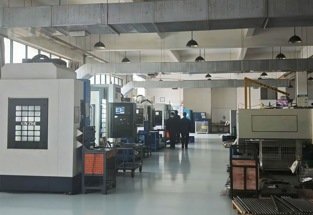
Nossa principal força reside na integração de toda a cadeia industrial, desde usinagem de precisão, processamento de chapas metálicas de precisão, produção de estampagem, projeto e fabricação por encomenda, tratamento de superfície profissional por pulverização até a montagem final do produto, implementando um sistema de gestão da qualidade excepcional em todo o processo. Isso significa que os clientes não precisam coordenar vários fornecedores para obter serviços eficientes, coordenados e consistentes. Nosso rigoroso controle de qualidade é implementado em cada etapa, garantindo que o que é entregue, em última análise, não sejam apenas peças ou produtos que atendam aos requisitos, mas também soluções globais estáveis, confiáveis e de alto padrão, ajudando efetivamente os clientes a reduzir prazos de entrega, custos e a melhorar a eficiência da cadeia de suprimentos.
Processamento personalizado de componentes não padronizados. Isso depende da complexidade do produto. O prazo de entrega geralmente varia entre 2 e 4 semanas.
25
Anos de experiência



















Contate-nos
artigos recentes
artigos recentes
Precisa de soluções mecânicas e elétricas ou tem alguma dúvida? Entre em contato!
Tapping vs. Thread Milling for CNC-Machined OEM Parts: Choosing the Right Internal Thread Process
23
Outubro
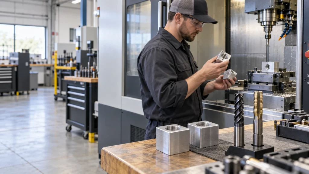
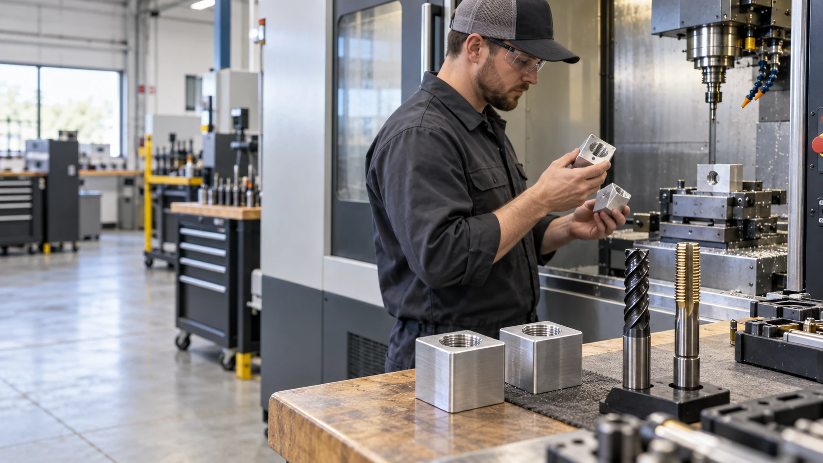
The choice between tapping and thread milling depends on the hole, material, thread specification, production quantity, machine capability, and cost of failure. Tapping is usually the faster route for repeat production of standard internal threads. Thread milling offers more control over thread size and fit, handles a wider range of diameters with fewer tools, and can reduce the consequence of a tool failure in a valuable part.
Neither process is universally better. A through-hole in a stable aluminum part may favor tapping, while a large thread, difficult material, expensive near-finished component, or close fit adjustment may justify thread milling. Blind-hole geometry and usable thread depth can change the answer again.
Tapping vs Thread Milling at a Glance
| Decision factor | Tapping | Thread milling |
| Cycle time | Often faster for standard repeated threads. | Usually longer because the tool follows a helical path. |
| Tool flexibility | One tap normally matches a specific size, pitch, and form. | One cutter may cover multiple diameters that share a compatible pitch and profile. |
| Fit adjustment | Limited after the tap and hole preparation are selected. | Tool-path offsets can adjust the finished thread within process limits. |
| Failure risk | A broken tap may be difficult to remove from the part. | A smaller cutter may be easier to recover from, but breakage can still damage the feature. |
| Machine need | Requires controlled feed and rotation appropriate to the tapping method. | Requires CNC helical interpolation, suitable control, rigidity, and access. |
How Each Process Cuts an Internal Thread
Both methods begin with a prepared hole, but their tool engagement is different. The drawing must specify the finished thread; the process planner then selects the pre-hole, tool, cutting data, and inspection route.
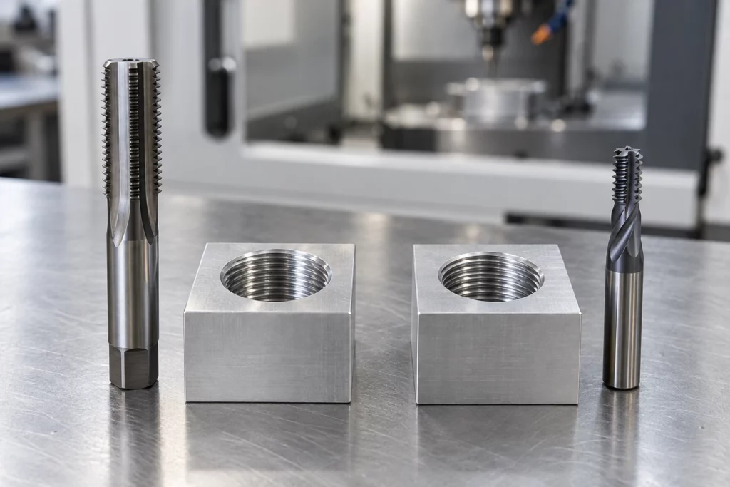
Tapping
A tap advances axially while its cutting edges or forming lobes create the complete thread profile. Because the tool engages around the circumference, torque, alignment, lubrication, chip control, and the prepared-hole diameter are important. Cut taps generate chips. Form taps displace suitable ductile material without chips, but they require a different hole size and should be approved for the material and specification.
Thread Milling
A thread mill rotates while the CNC moves it along a helical path. The cutter is smaller than the finished thread, so it engages a portion of the circumference at a time. The program controls diameter and direction, and suitable cutters can produce internal or external threads. The method needs enough bore access, tool clearance, machine interpolation, and stable workholding.
Choose by Hole Geometry
Through Holes
Through holes usually provide easier chip evacuation and fewer bottom-clearance constraints. For standard sizes and meaningful batch quantities, tapping often provides the most efficient cycle. A spiral-point cutting tap may push chips ahead through the opening when the material and application permit. Thread milling remains useful for large diameters, adjustable fits, mixed thread sizes, or parts where tool-breakage recovery influences the risk calculation.
Blind Holes
Blind holes need separate values for drilled depth, full thread depth, usable engagement, and bottom clearance. A tap has an incomplete lead before it produces full threads, and chips must have somewhere to go. Tap style, coolant delivery, chip evacuation, and reversal therefore matter. Thread milling can approach a shoulder with controlled axial positioning, but it still needs entry and exit clearance and cannot create usable thread beyond its programmed geometry. Do not specify “thread to bottom” without defining a manufacturable termination.
Choose by Material and Thread Specification
Material behavior affects torque, chips, tool wear, heat, and edge quality. Standard threads in machinable aluminum may favor tapping for speed, although chip packing or built-up edge still needs control. Tough stainless steels, high-temperature alloys, or expensive heat-treated parts may make the lower engagement and recovery advantages of thread milling more attractive. The supplier should confirm the exact alloy, hardness, and hole depth before choosing the route.
Thread size and form matter as much as material. Small standard threads may suit tapping, while larger diameters, special profiles, right- and left-hand variants, or adjustable fit classes can favor thread milling. A thread mill is not universal: its diameter, pitch capability, length, cutting form, and reach must match the feature.
Choose by Quantity and Cost of Failure
For a stable high-volume job, the shorter cycle of tapping can outweigh its lower flexibility. For prototypes and mixed families, thread milling may reduce the number of dedicated tools and allow diameter correction through offsets. The value of the workpiece also matters. Breaking a tap in an almost-complete housing can cost more than the saved cycle time; however, thread milling adds programming time and may use a more expensive cutter. Compare total route cost, not tool price alone.
Define the Thread Correctly on the Drawing
A process comparison cannot correct an incomplete specification. Use the same feature-based discipline applied to CNC machining tolerances, and include the following information:
- Thread standard and designation, nominal size, pitch or threads per inch, internal class or tolerance, and right- or left-hand direction.
- Through or blind condition, drilled depth, full thread depth, minimum usable engagement, entrance chamfer, and any bottom-clearance limit.
- Material grade and condition, heat treatment, coating or plating, quantity, critical datum relationships, and mating-fastener information.
- Inspection method, gauge standard, sampling level, first-article record, and any functional assembly test.
A complete CNC machining RFQ checklist also keeps model, drawing, revision, finish, and inspection assumptions consistent across bidders.
Verify the Sample and Production Route
Inspect the pre-hole as well as the finished thread. Confirm location, diameter, depth, chamfer, burr condition, and cleanliness. Use the specified GO and NO-GO gauges or another agreed method, then test the real mating fastener when assembly behavior matters. Record tool offsets and wear limits for thread milling, or torque, tap life, and chip-control checks for tapping. A first article should also confirm that coating, plating, or heat treatment does not invalidate the final fit.
Evaluate Supplier Capability Against the Part
CK Metal Tech publishes precision machining capabilities that include CNC milling, drilling, tapping, and related inspection resources. Its broader CNC machining services for precision metal parts provide the context for OEM process planning. The project review should still confirm whether tapping, thread milling, or another threading method is available and appropriate for the specific size, material, depth, tolerance, quantity, and inspection plan.
Conclusão
Use tapping when a standard internal thread, suitable material, controlled hole, and repeat quantity make cycle time the priority. Consider thread milling when fit adjustment, large or varied sizes, difficult materials, blind-hole constraints, or the cost of a trapped broken tap changes the economics. The drawing and sample plan should make the choice verifiable rather than leaving it to habit.
Perguntas frequentes
Is Thread Milling Always More Accurate Than Tapping
No. Either process can make acceptable threads when the machine, tool, hole preparation, setup, and inspection suit the requirement. Thread milling offers useful diameter adjustment, but it does not replace process control.
Which Process Is Better for Blind Holes
It depends on usable depth, bottom clearance, material, chip control, thread size, and quantity. A suitable tap can be efficient; thread milling can improve control where evacuation or failure consequences are difficult.
Can One Thread Mill Cut Several Thread Sizes
Sometimes. A cutter may cover multiple diameters with a compatible pitch and profile, within its diameter and reach limits. Confirm the tool manufacturer’s range and the required thread form.
How Should an Internal Thread Be Inspected
Use the drawing’s specified gauge or measurement method and sampling plan. GO and NO-GO gauges are common, but depth, location, surface condition, and functional assembly may also require verification.
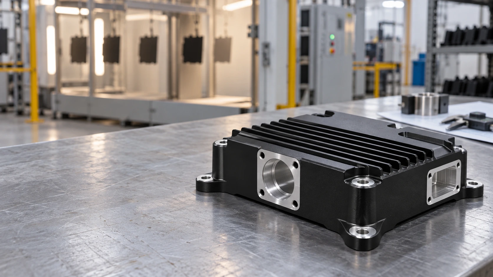
Can CNC-Machined Aluminum Housings Be Powder Coated? Thermal Interfaces, Fits, and Masking
22
Outubro
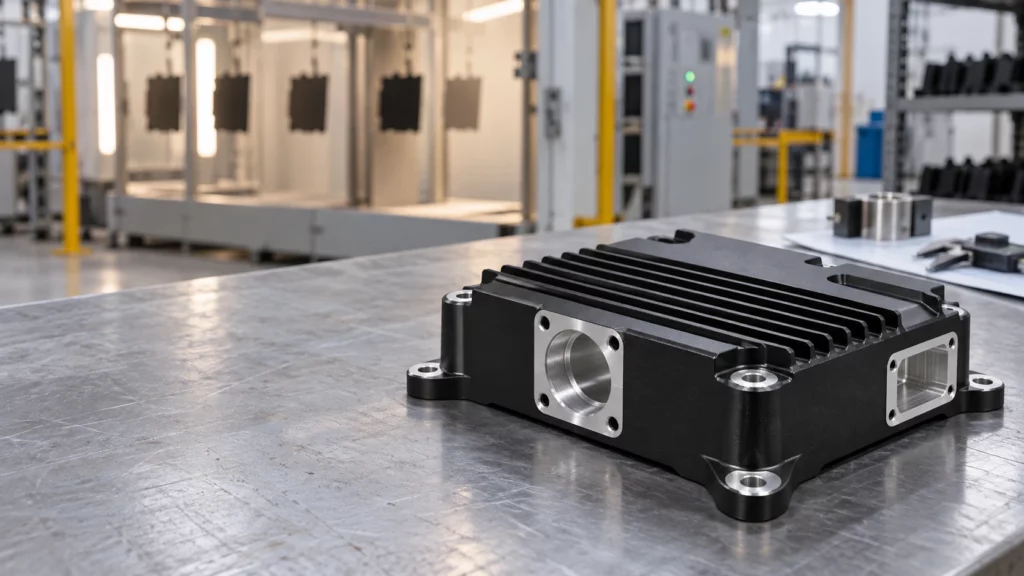
Can aluminum be powder coated after CNC machining? Yes, provided the drawing distinguishes cosmetic or protective surfaces from interfaces that must remain dimensionally, electrically, or thermally functional. A coating that performs well on an exterior wall can cause interference in a close fit, obstruct a thread, insulate a bonding point, or add thermal resistance at a heat-transfer joint.
The review should therefore start with the finished assembly, not the color. CK Metal Tech’s aluminum alloy cooling and shielding cover plate illustrates why this distinction matters: one machined component may combine an exterior cover, mounting holes, grooves, structural bosses, shielding functions, and heat-dissipation duties. Those surfaces should not automatically receive the same finish treatment.
Map Functional Surfaces Before Coating
Create a finish map on the controlled drawing or model. Identify coated faces, cosmetic faces, no-coat zones, and surfaces whose final dimensions apply after finishing. A generic note such as “powder coat black” does not tell the manufacturer how the housing must assemble or perform.
Surfaces Commonly Suitable for Coating
Exterior walls, non-mating covers, guards, and handling surfaces are typical candidates when the selected pretreatment and powder system match the aluminum alloy and service environment. Coating can support appearance and surface protection, but corrosion, chemical exposure, ultraviolet exposure, and cleaning requirements still need project-specific confirmation.
Surfaces That Often Need Masking
Common no-coat candidates include bearing or bushing seats, locating datums, close-tolerance bores, sliding rails, O-ring lands, sealing faces, connector grounds, threaded holes, fastener seats, and direct thermal contact pads. The decision is functional rather than categorical: a clearance hole may tolerate film build, while a locating hole with the same nominal diameter may not.
Mask Boundaries Need Their Own Definition
A no-coat note should show where the boundary begins, which direction the mask may shift, and whether a small transition band is acceptable. This is important around countersinks, spotfaces, grooves, stepped bores, gasket lands, and thermal pads. Masking has practical placement variation, and the cured edge may not form a perfectly sharp geometric line. Keep the boundary away from a sealing path or precision datum where possible. If the transition itself affects function, dimension it from a stable feature and include it in the first-article inspection plan.
How Powder Coat Changes Functional Interfaces
Powder coating adds material to the surfaces it covers. The actual build depends on the powder, application, grounding, part geometry, racking, and cure route, so the drawing should define the finished requirement instead of assuming a universal allowance.
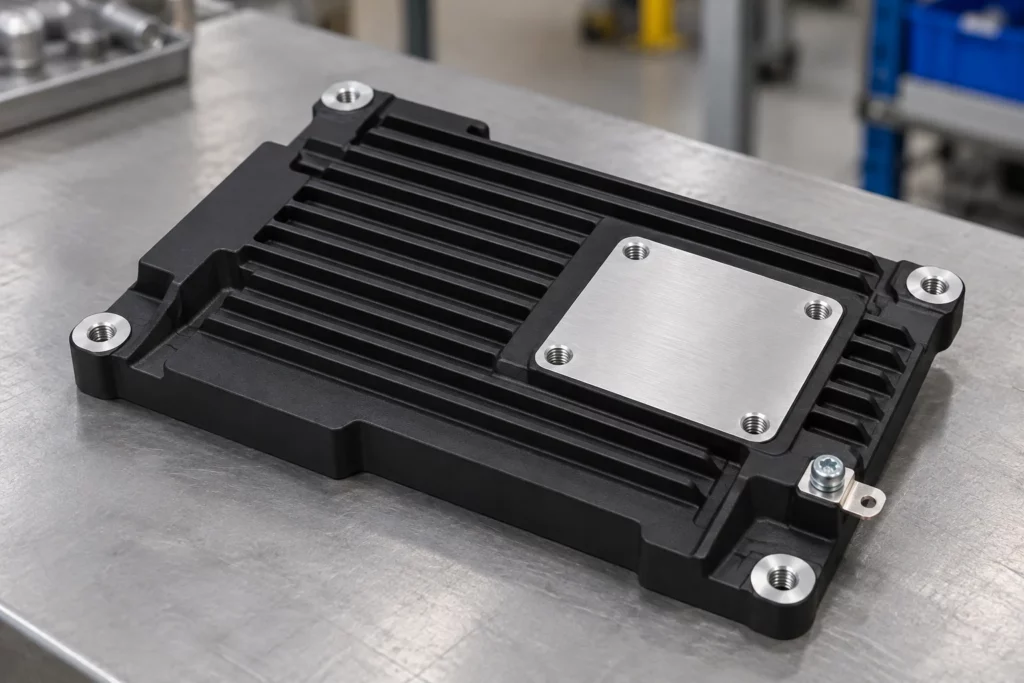
| Feature | Coating risk | Drawing or process control |
| Fits and threads | Film build reduces clearance and can obstruct engagement. | Mask, allow for the finish, or approve controlled post-coat machining. |
| Grounding points | The organic film can interrupt metal-to-metal electrical contact. | Mark bonding pads and define continuity or resistance verification. |
| Thermal interfaces | The coating and any trapped air can add resistance at a contact joint. | Keep direct-contact pads bare when required and define flatness, pressure, and interface material. |
| Sealing and datums | Build-up or an uneven mask edge can change seating and measurement references. | State whether dimensions apply before or after coating and locate mask boundaries. |
Fits and Threaded Features
Check each fit against its mating component and the finished-state tolerance. The same feature-level reasoning used for CNC machining tolerances applies after coating. Thread masks must protect the required diameter, lead-in, and usable depth. Forcing a screw through cured powder is not a controlled acceptance method because it can damage the finish and leave debris in the assembly.
Grounding and Thermal Contact
A designated grounding pad needs a clean boundary, a suitable fastener interface, and a defined verification method. Bare aluminum may also need a compatible protection strategy that preserves conductivity. For heat-transfer pads, evaluate coating together with contact area, surface flatness, clamping pressure, and any thermal interface material. A sample should be tested under representative heat load when temperature performance is critical.
Coordinate CNC Machining and Powder Coating as One Route
The safest sequence is established before chips are cut. Treat masking, finishing, and final inspection as part of the manufacturing plan rather than instructions added after machining.
- Review the current drawing, aluminum grade or approved alternative, functional interfaces, cosmetic zones, and operating environment.
- Machine the housing with any agreed allowance for surfaces controlled in the finished state; deburr edges without altering critical geometry.
- Clean and pretreat the part using a route compatible with the alloy, contamination condition, and specified coating system.
- Install plugs, caps, or high-temperature masking at the defined boundaries, then verify mask seating before spraying.
- Apply and cure the coating, remove masks cleanly, and inspect boundaries for lifting, chips, or unintended coverage.
- Complete only approved secondary machining or thread restoration, then clean the part and protect newly exposed aluminum as required.
An integrated review can connect the company’s precision machining capabilities with its powder coating service. The exact masking materials, post-coat operations, and inspection methods should still be confirmed for the part.
Verify the First Article Before Production
A first article should prove more than color and appearance. Use the actual mating components or representative gauges where possible, and record the drawing revision and coating specification used for approval.
- Dimensions: measure critical fits, datums, hole locations, and flatness in the state specified on the drawing.
- Assembly: install fasteners, covers, seals, rails, connectors, and locating features without forcing or finish damage.
- Electrical function: verify required bonding or shielding continuity at the specified contact points.
- Thermal function: check temperature performance under a representative load when the housing forms part of the heat path.
- Finish: inspect coverage, cure evidence, mask edges, handling damage, and cosmetic acceptance against an agreed reference.
Record nonconforming features separately. A part should not pass because its exterior looks uniform when a thread, bonding pad, thermal interface, or locating surface fails its own requirement.
What to Put in the Drawing and RFQ
Submit the 2D drawing and 3D model with material, quantity, coating system or performance requirement, color and texture, finished-state dimensions, no-coat zones, mask depth, thread callouts, grounding locations, thermal pads, inspection records, mating-part information, and sample approval criteria. Separate prototype quantity from expected production volume so the supplier can evaluate masking fixtures and process controls appropriately.
Conclusão
CNC-machined aluminum housings can be powder coated successfully when the finish map protects the part’s working interfaces. The design should preserve required clearance, thread engagement, electrical bonding, and thermal contact, while the process plan should connect machining, pretreatment, masking, coating, and finished-state inspection.
Perguntas frequentes
Should Every Threaded Hole Be Masked
No. Masking depends on thread function, fastener fit, engagement depth, and the approved finishing route. The drawing should identify which threads must remain coating-free and how they will be checked.
Can Powder Coat Be Allowed for in a Close Fit
Sometimes, but the designer and manufacturer must agree on the final clearance and whether the controlling dimension applies before or after coating. Do not rely on a generic film allowance.
Should a Thermal Contact Pad Remain Bare
Often it should when direct metal contact is part of the heat path. Confirm the complete joint, including flatness, contact pressure, interface material, corrosion protection, and the required thermal test.
Is Post Coating Machining Acceptable
It may be, if the operation is planned. Control chips, protect the surrounding finish, re-inspect dimensions, and define how newly exposed aluminum will be handled.
Request a Joint Machining and Coating Review
Send CK Metal Tech the drawing revision, alloy, quantity, mating-part details, coating requirements, no-coat zones, thermal duty, grounding needs, and inspection expectations. Use the request a joint machining and coating review route to confirm the manufacturing sequence before quotation.
One Metal Supplier vs Multiple Vendors: How to Calculate Total Landed Cost
16
Outubro
One metal supplier can reduce transfers between fabrication, finishing, and assembly, but supplier consolidation does not automatically lower total landed cost. Compare both routes at the same delivery destination, then add the buyer-side costs needed to turn delivered parts into accepted assemblies. Keep those layers separate: shipping and import charges belong in the landed-cost calculation; supplier administration, inventory, and integration costs belong in the broader sourcing decision.
For an OEM buying custom metal parts, this distinction prevents a lower piece price from hiding extra work. It also avoids calling every future operating expense a landed cost.
Define the Deliverable Before Comparing Vendors
Start with one controlled bill of materials and drawing revision. Specify material, finish, quantity, inspection criteria, packaging, destination, and assembly responsibility. A coated panel from one vendor cannot be compared directly with an assembled enclosure from another unless the missing operations are priced separately.
Distinguish process splitting from dual sourcing. Sending cutting to one shop and coating to another creates sequential handoffs. Qualifying two independent suppliers for the same finished assembly creates a backup route. These arrangements have different costs and continuity benefits; combining them under “multiple vendors” obscures the decision.
Calculate Total Landed Cost in Two Layers
The core shipment calculation is:
Landed cost = supplier invoices + separately charged tooling + packaging + freight + insurance + applicable duties, taxes, and clearance fees.
The International Trade Administration’s landed-cost guidance supports the product-plus-delivery approach. For metal parts, verify which charges are already included in each quotation. Add only costs outside the quoted scope, and use the same receiving location.
Then calculate a separate management metric:
Sourcing comparison cost = landed cost + buyer assembly and inspection + supplier administration + inventory carrying cost + evidence-based quality and disruption allowances.
This second formula is a purchasing decision tool, not a customs valuation or accounting rule. It does not include equipment operating costs over the product’s lifetime. Keep recoverable taxes and other accounting treatments identifiable for finance review rather than treating every cash payment as a permanent expense.
Normalize Quotes and Allocate Shared Charges
Use the same currency, demand period, release size, and named delivery point. Record the delivery term and which party pays each freight leg. A quote that includes shipping can appear expensive beside a factory-gate quote until the missing freight is added.
For international purchases, ask a qualified broker to verify classification, origin, applicable charges, and the relevant shipment date. Do not copy a tariff percentage from another part or last year’s order.
Allocate shared freight across a mixed shipment using a defensible driver, such as chargeable weight or occupied volume. Allocate tooling over the realistically committed program quantity, with tooling ownership shown separately. Show first-order and repeat-order costs independently; an optimistic lifetime volume can conceal a costly launch.
A Worked Example for One Thousand Assemblies
The following figures are hypothetical USD amounts, not CK Metal Tech quotations or tariff estimates. Both routes ultimately provide 1,000 accepted assemblies. The single supplier includes assembly in its invoice; the split route requires more buyer assembly work. Charges already included in supplier invoices are excluded from the other rows.
| Cost category | One supplier | Multiple vendors |
| Supplier invoices | $40,000 | $37,000 |
| Tooling and setup | $3,000 | $2,200 |
| Packaging freight and insurance | $1,800 | $3,300 |
| Illustrative import and clearance charges | $1,500 | $1,500 |
| Core landed cost | $46,300 | $44,000 |
| Buyer assembly and inspection | $800 | $3,300 |
| Supplier administration | $400 | $1,200 |
| Inventory carrying cost | $600 | $1,100 |
| Expected quality and rework allowance | $600 | $1,800 |
| Sourcing comparison total | $48,700 | $51,400 |
| Cost per accepted assembly | $48.70 | $51.40 |
Multiple vendors win the core landed-cost comparison by $2,300. After buyer-side costs are included, one supplier is lower by $2,700. This result follows the stated assumptions; it does not prove that consolidation is generally cheaper.
The decision changes if the split route reduces internal assembly effort, avoids quality losses, or provides a valuable qualified backup. Replace every allowance with program evidence before using this example for an award decision.
Measure Handoffs Without Double Counting
Map the route from cutting and forming through machining, coating, final inspection, and packing. Sheet metal fabrication may involve several linked operations, so track the transfers between them rather than counting suppliers alone.
For each handoff, record transport, protective packaging, receiving inspection, queue time, and revision-control responsibility. Estimate internal work from hours multiplied by an approved labor rate. Distinguish cash savings from staff capacity released: fewer purchase orders do not necessarily reduce payroll.
Estimate inventory carrying cost from average inventory value, the approved annual carrying rate, and the time period. Use historical rework and expedite costs where available. For a new program, show low, expected, and high cases rather than inventing a precise failure probability.
Avoid charging the same loss twice. If rejected units already reduce the accepted-unit denominator, check whether a separate scrap allowance repeats that loss. Likewise, do not add replacement freight when it is already included in a rework estimate.
Choose the Route and Test Its Weak Points
One supplier is attractive when interfaces dominate the program: welded frames must match machined brackets, coating boundaries affect fit, and completed assemblies require a coordinated release. Multiple vendors may be preferable when a process needs specialist qualification, capacity is constrained, or a genuinely independent backup is essential.
A backup is only useful if drawings, tooling access, qualification status, and available capacity make it executable. Two suppliers sharing the same critical subcontractor may still have a common interruption risk. Keep continuity requirements visible beside the cost comparison.
Test the decision against smaller releases, a rejected batch, an engineering change, and an expedited shipment. If the winner changes under a small assumption adjustment, resolve that uncertainty before committing the production route.
Request a Comparable Metal Manufacturing Quote
CK Metal Tech combines sheet metal processing, machining, stamping, powder coating, painting, and precision-component assembly. Review its metal manufacturing and assembly capabilities against the proposed route; process breadth alone does not establish capacity or suitability for a particular program.
Send the BOM, controlled drawings, quantities, destination, finish requirements, and acceptance plan. Ask CK Metal Tech to separate tooling from recurring prices and identify subcontracted operations, excluded services, and packing assumptions. Give alternative vendors the same package.
Conclusão
Choose the sourcing route using both delivered cost and the work required to obtain accepted assemblies. A transparent comparison can show that multiple vendors win on landed cost while one supplier wins after integration costs, or the reverse. Award the route whose cost assumptions and continuity requirements can be verified.
Perguntas frequentes
Is one metal supplier always cheaper
No. Consolidation may reduce transfers and administration, while multiple vendors can provide specialist capability or backup capacity. Compare equivalent outputs and documented costs.
Is total landed cost the same as total cost of ownership
No. Landed cost addresses acquisition and delivery. Ownership cost extends into use, maintenance, and disposal. Buyer integration costs should remain a clearly labeled comparison layer.
How should tooling be included
Show the initial tooling payment separately, then allocate it across a defensible committed quantity for the unit comparison. Record ownership, maintenance responsibility, and repeat-order assumptions.
Should supplier management time count as a saving
Include it when comparing resource demand, but distinguish released staff capacity from actual cash savings. Use measured hours and an approved rate.
Request a Sourcing Route Review
Share the current drawings, BOM, delivery location, release schedule, and assembly scope with CK Metal Tech. Request a sourcing-route review to clarify included operations and compare the assumptions behind each quotation.