







-
Ускоренное изготовление прототипов за 1–3 дня и гибкая, оперативная цепочка поставок.
-
Твердая приверженность своевременной отгрузке и неизменно высокому качеству продукции.
-
Широкий выбор материалов + полный спектр стандартных для промышленного применения методов обработки поверхности.
-
Предложение напрямую от производителя и полностью открытая, прозрачная смета расходов.
-
Система управления качеством сертифицирована в соответствии со стандартами ISO 9001:2015 / IATF 16949:2016.
-
Комплексная сборочная услуга «под ключ»: мы поставляем готовые к использованию изделия и отдельные запасные части.
Комплексные услуги по изготовлению металлических изделий на заказ: от прототипирования до серийного производства.
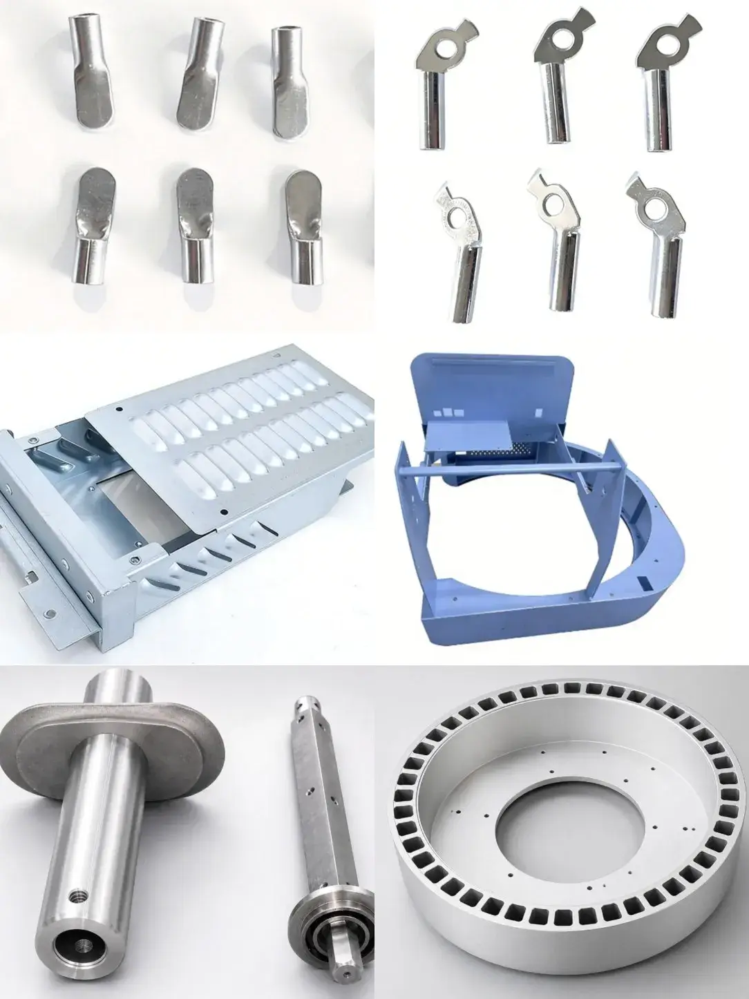
поддержка разнообразных инженерных и производственных применений.
-
Конкурентные цены и DFM
-
Круглосуточная инженерная поддержка.
-
Быстрое выполнение заказа, короткие сроки поставки, без минимального объема заказа.
Проверка сертификатов по запросу: IS0 9001:2015|IATF 16949:2016

о чуанкае
Компания Zhejiang Chuangkai Mechanical and Electrical Technology Co., Ltd. была основана в марте 2003 года с уставным капиталом в 15 миллионов юаней. Компания является высокотехнологичным предприятием, объединяющим проектирование и производство прецизионных инструментов, прецизионную штамповку металла, прецизионную обработку листового металла, прецизионную механическую обработку, покраску, порошковую покраску и сборку прецизионных компонентов. В настоящее время в компании работает 95 сотрудников, она располагает современным прецизионным обрабатывающим оборудованием и стандартизированными цехами общей площадью около 13 500 квадратных метров. Компания имеет сертификаты ISO9001, IATF16949, ISO45001 и ISO14001.

Проектирование и изготовление прецизионных штамповочных инструментов.

Основное штамповочное оборудование в штамповочном цехе: 18 комплектов высокоскоростных прецизионных штамповочных прессов с номинальными параметрами 16 тонн, 25 тонн, 40 тонн, 60 тонн, 80 тонн, 110 тонн, 200 тонн и 250 тонн. Скорость работы прецизионных высокоскоростных штамповочных прессов может достигать 500 оборотов в минуту.
Материалы для штамповки: латунь, фосфористая бронза, бериллиевая бронза, никель-белая медь, а также различные виды стали и нержавеющей стали, никелевые полосы, холоднокатаная сталь, полосовая сталь (включая предварительно покрытую), оцинкованные листы, низкоуглеродистая сталь, пружинная сталь и другие композитные материалы.
Производство листового металла с высокой точностью
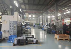
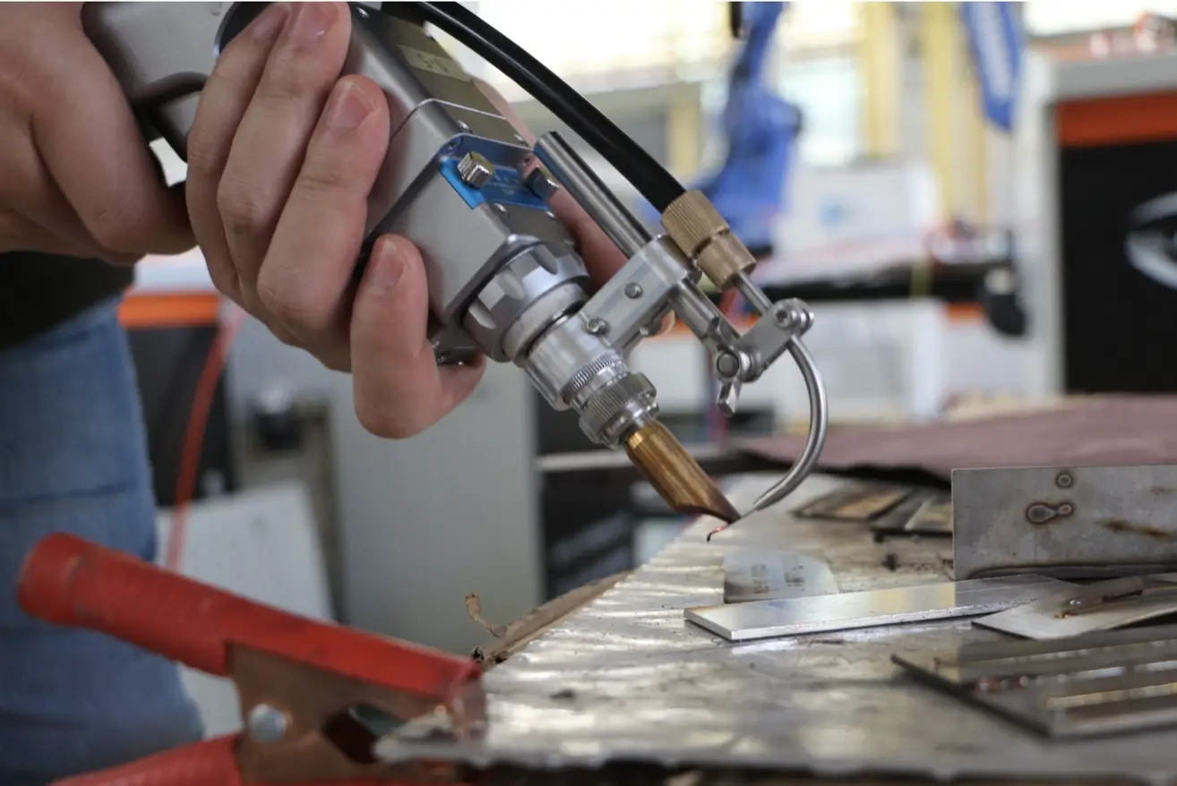
Цех обработки листового металла оснащен высокоточным оборудованием для обработки листового металла, включая 2 крупногабаритных современных станка лазерной резки с ЧПУ, 1 штамповочный пресс с ЧПУ, 5 гибочных станков с ЧПУ, а также клепальные машины, сварочные аппараты, шлифовальные станки, волочильные станки и другое оборудование.
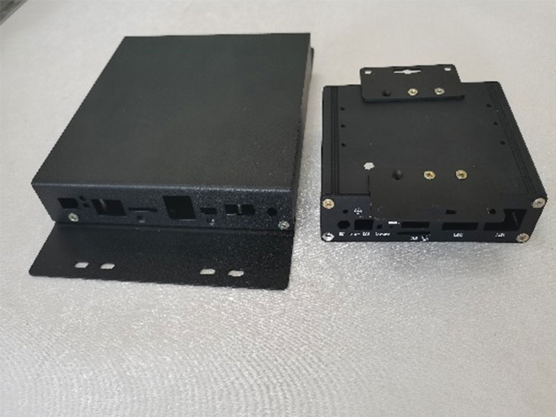
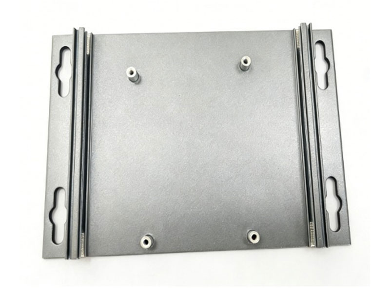
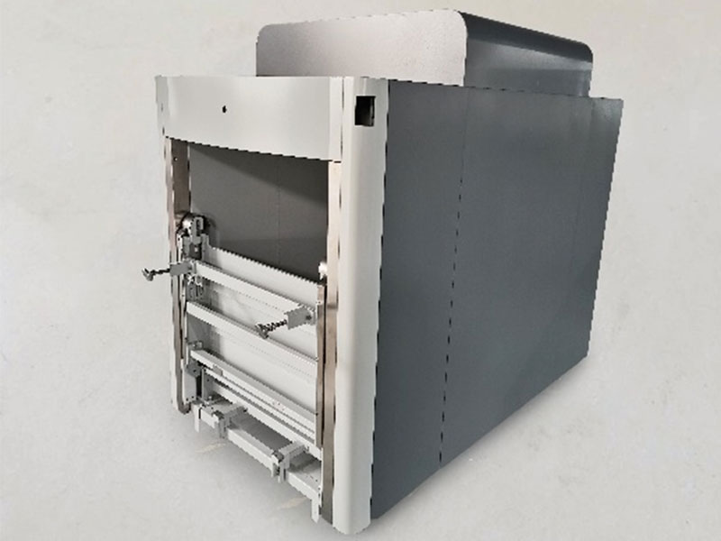
Обрабатываемая продукция охватывает промышленную автоматизацию, медицинское оборудование, электрооборудование, электромонтажные коробки, распределительные коробки и другие области. Возможно выполнение высокоточной обработки, такой как быстрая резка и обработка листового металла, следующих материалов: нержавеющая сталь, углеродистая сталь, кремниевая сталь, алюминиевые сплавы, оцинкованный лист, алюминиево-цинковый лист и др.
Порошковая покраска
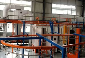
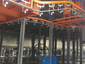
Одна автоматизированная линия порошковой окраски;
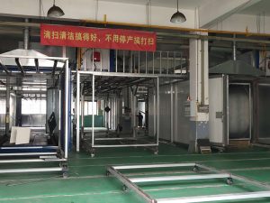
Одна линия ручной порошковой окраски (для крупных деталей и больших коробок);
Одна линия ручной покраски (для крупных деталей и больших коробок);
В стадии строительства находится одна автоматизированная гибридная линия порошковой окраски и нанесения порошкового покрытия.
Прецизионная обработка

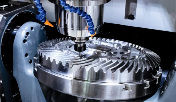
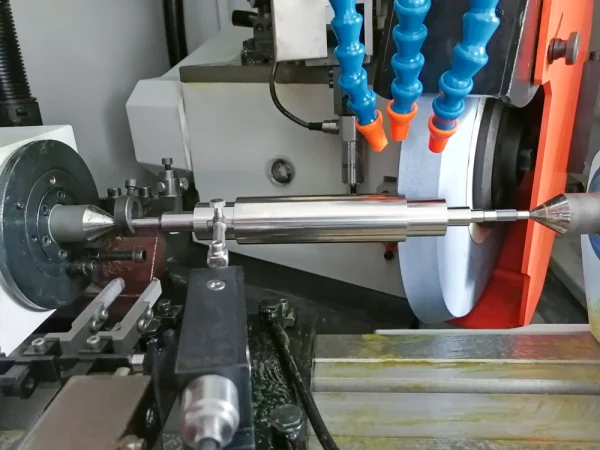
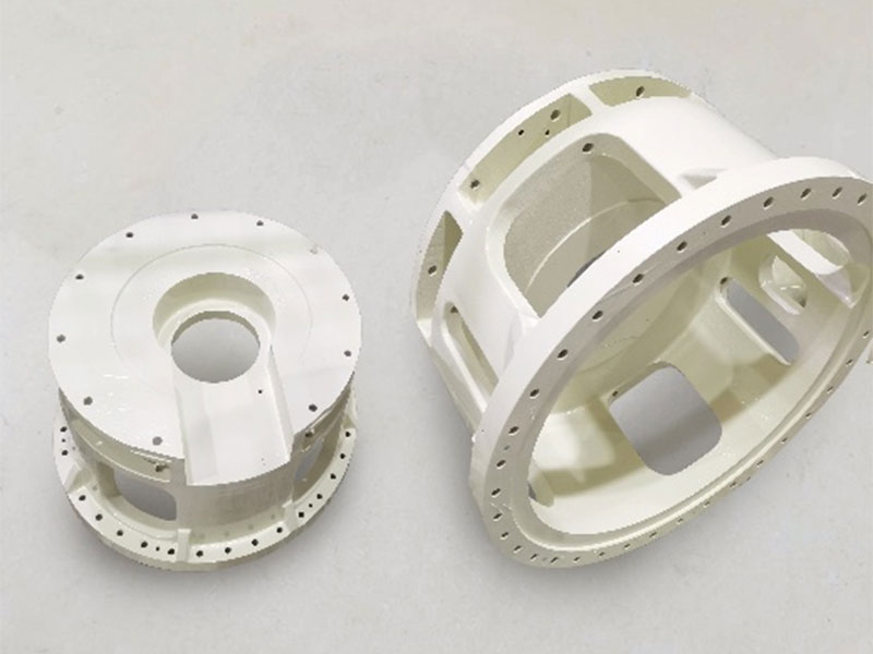
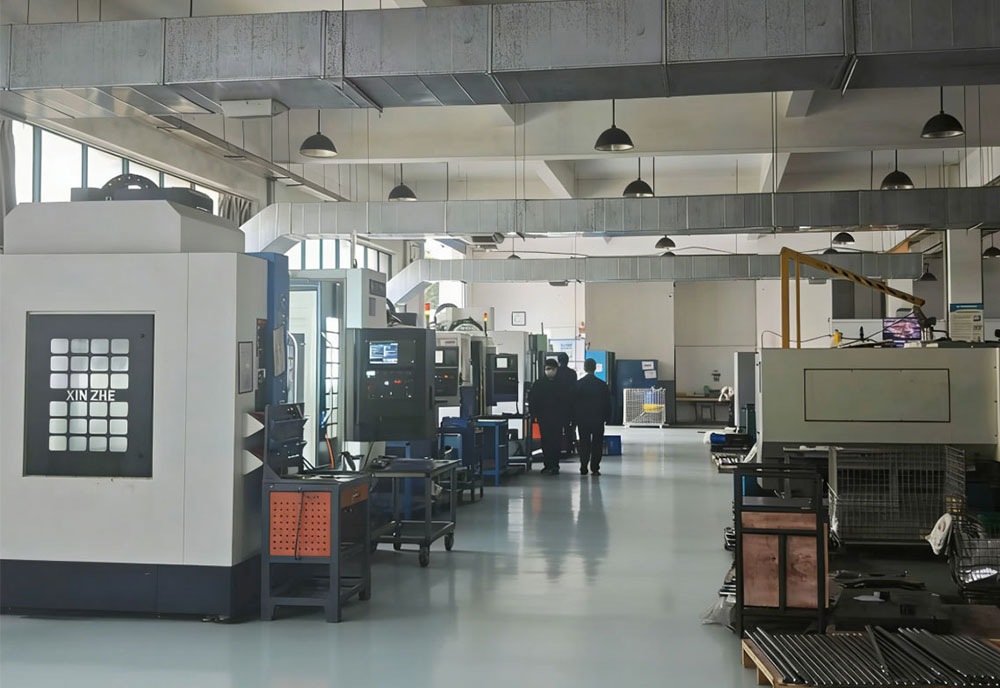
Механический цех оснащен высокоточным оборудованием, включая 6 комплектов 4-осевых станков с ЧПУ, 1 комплект 5-осевых токарных станков швейцарского типа, 13 комплектов прецизионных токарных станков с ЧПУ, 4 комплекта фрезерных станков с ЧПУ, 16 комплектов прецизионных автоматических токарных станков Mingyang производства Тайваня, а также прецизионные обычные токарные станки, прецизионные 3-осевые фрезерные станки с цифровым дисплеем, прецизионные настольные токарные станки, автоматические кромкофрезерные станки Jizuan производства Тайваня, прецизионные резьбонакатные станки, резьбонакатные штампы, прецизионные резьбонакатные станки, прецизионные сверлильные станки, прецизионные фрезерные станки с цифровым дисплеем производства Тайваня, прецизионные заточные станки для ножей, внутренние и наружные цилиндрические шлифовальные станки, бесцентровые шлифовальные станки, пильные станки, ультразвуковые очистительно-сушильные машины, полировальные станки, электросварочные аппараты, дуговые сварочные аппараты и другое оборудование.
наш
Вступительное видео
наши интересные факты
Больше не нужно координировать действия более чем 5 поставщиков. Экономия затрат – разумное производство: вертикальная интеграция + оптимизация процессов = снижение затрат на 15-30% по сравнению с разрозненными цепочками поставок.
Быстрый вывод продукции на рынок: параллельное проектирование сокращает сроки выполнения на 40%. Соблюдайте сроки без ущерба для качества.
Запросите бесплатный DFM-анализ: загрузите свои чертежи/образцы. Наши инженеры определят возможности оптимизации затрат и эффективности в течение 48 часов.

компания построена
0
зарегистрированный капитал
0М
персонал
0+
заводская зона
0+
наш случай
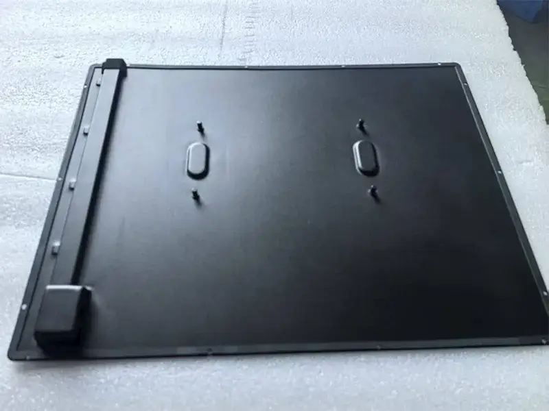
Использование процесса растяжения является альтернативой технологии сварки+полировки+зачистки шпатлевкой.
Использование процесса растяжения является заменой сварке и полировке. +Соскребок для шпаклевки Технологии
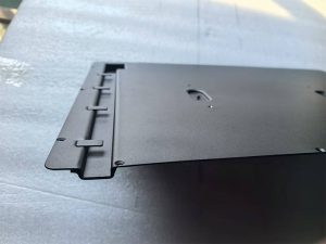
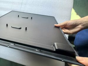
Преодолейте технические препятствия и создавайте высококачественные и доступные по цене металлические конструкционные детали для учебного демонстрационного оборудования:
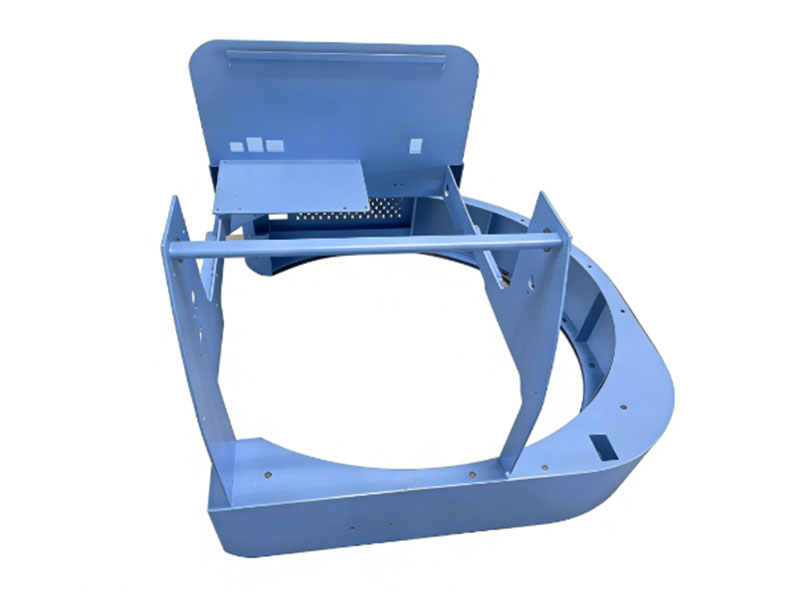
При разработке заказчиком большого демонстрационного компьютера для обучения и тренировок возникли серьезные проблемы с его основными металлическими конструкционными элементами. Первоначальная конструкция детали предусматривала сварку выступающих частей, но на этапе тестирования изделия низкая герметичность сварных швов не позволила ему пройти ключевые испытания. В то же время, высокая стоимость процесса сварки значительно завышает цену деталей по сравнению с конкурентами, сроки сдачи проекта неумолимы, и заказчик испытывает сильное давление в отношении качества и стоимости.
Точно выявляйте болевые точки и оперативно реагируйте, чтобы их устранить:
Поняв проблему, с которой столкнулся клиент, мы оперативно сформировали специальную техническую группу. На первом техническом семинаре мы провели углубленный анализ первопричин низкой герметичности сварных швов. Хотя благодаря оптимизации параметров сварки и внедрению сварочного оборудования и привлечению специалистов мы успешно решили проблему герметичности и удовлетворили первоначальные требования клиентов к качеству, проблема высокой стоимости сварки остается нерешенной.
Инновационный план, состоящий из двух этапов:
Техническая команда на этом не остановилась. После многочисленных внутренних обсуждений и тесного взаимодействия с клиентами мы предложили принципиальное решение: заменить оригинальную сварку интегрированным процессом штамповки и растяжения + полировки + шпаклевки. Это не только полностью исключает риск заедания сварных швов, но и значительно снижает себестоимость производства, а также предоставляет продукту возможность завоевать большую долю рынка.
«Сделай невозможное», исполни обещание:
В ходе обсуждения с клиентами рассматривался вариант штамповки с расширением масштабов производства, однако другие поставщики заявили о невозможности его реализации. В условиях постоянных вопросов мы твердо убеждены, что «учишься на практике». Основываясь на глубоком накоплении технологий, мы предлагаем клиентам ключевые рекомендации по оптимизации, в том числе:
Для оптимизации текучести материала отрегулируйте угол наклона зоны растяжения и выберите стальную холоднокатаную пластину определенной марки с лучшими прочностными характеристиками.
Отличные результаты, высоко оцененные клиентами:
После утверждения плана мы провели несколько этапов тщательных технологических испытаний и проверки образцов. Готовые детали идеально соответствуют проектным требованиям и стандартам производительности заказчика. Заказчик был чрезвычайно доволен результатами и не только высоко оценил их: «Это идеальный продукт, соответствующий моим идеальным проектам!», но и выразил искреннюю благодарность команде Chuangkai за умение преодолевать сложные проблемы. Мы успешно помогли клиентам в сжатые сроки поставки, решив сложные проблемы качества и стоимости, и помогли их продукции получить конкурентное преимущество на рынке.
Преодоление технических препятствий для создания высококачественных и экономически эффективных металлических компонентов для образовательных дисплеев и систем.
Задача:
Клиент, разрабатывающий большие демонстрационные компьютеры для обучения и образования, столкнулся с критической проблемой, связанной с ключевым металлическим конструкционным элементом. Первоначальная конструкция предусматривала сварные выступы. Однако во время испытаний изделия низкая герметичность сварного шва привела к отказам. Ситуацию усугубляла высокая стоимость процесса сварки, из-за чего их компонент оказался значительно дороже, чем у конкурентов. В условиях приближающихся сроков выполнения проекта клиент находился под огромным давлением, стремясь решить как проблемы качества, так и финансовые вопросы.
Наше быстрое реагирование и первоначальное решение:
Узнав о проблеме клиента, мы незамедлительно сформировали специальную техническую группу. В ходе первоначального технического анализа мы тщательно изучили первопричину отказа уплотнения. Благодаря обширным испытаниям по оптимизации параметров сварки и стратегическому внедрению роботизированной сварки, мы успешно достигли требуемой герметичности, соответствующей спецификациям качества клиента.
Выявление глубинной проблемы и предложение инноваций:
Хотя непосредственная проблема герметизации была решена, фундаментальная проблема непомерно высоких производственных затрат оставалась. Не желая мириться с этим, наша рабочая группа провела интенсивный внутренний мозговой штурм и поддерживала тесную связь с клиентом. Мы предложили революционное решение: заменить сварную сборку цельным компонентом, изготовленным методом штамповки и глубокой вытяжки. Такой подход обещал:
- Устраните первопричину нарушений герметичности, присущих сварке.
- Достичь значительного снижения затрат за счет оптимизации производства.
- Повышение конкурентоспособности на рынке** конечного продукта клиента.
Преодоление «невозможного»:
Клиент сообщил, что ранее рассматривал вариант штамповки, но другие поставщики сочли его нецелесообразным для этой детали. Руководствуясь убеждением, что «доказательство — на практике», мы использовали наш технический опыт для предложения важных оптимизаций конструкции.
- 1. Регулировка угла вытяжки для улучшения потока материала.
- 2. Выбор высококачественной холоднокатаной стали с превосходными свойствами для глубокой вытяжки.
Успешный результат:
После тщательного прототипирования и валидационного тестирования на основе нашего оптимизированного проекта мы представили финальный компонент. Результаты превзошли все ожидания, идеально соответствуя проектным замыслам клиента и требованиям к производительности. Клиент выразил глубокое удовлетворение, высоко оценив проект: «Это идеальный продукт, который я представлял себе в своем проекте!». Он особо поблагодарил компанию ChuangKai за решение их давней технической проблемы. Мы помогли клиенту уложиться в критически важный срок, одновременно преодолев дефекты качества и ценовой барьер, что значительно повысило конкурентоспособность его продукции на рынке.
Пример из практики: усовершенствования в предотвращении поломок валов сельскохозяйственной техники
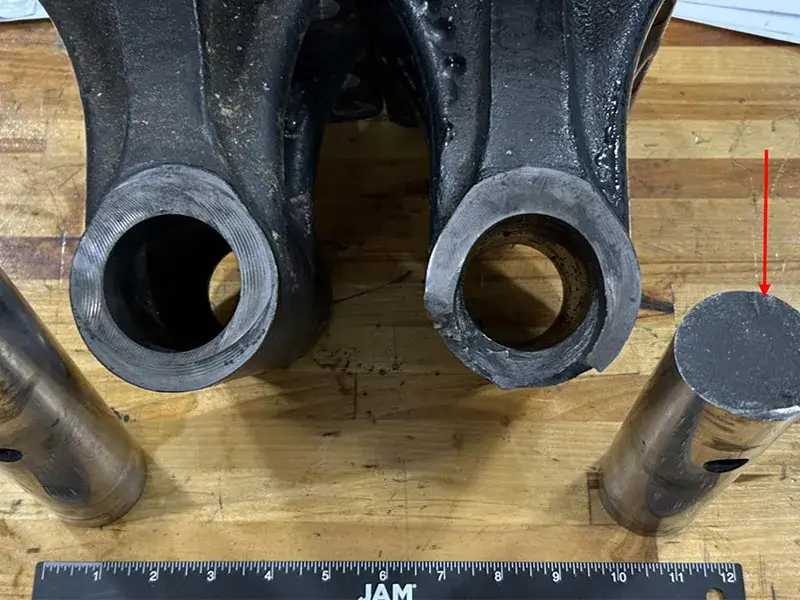
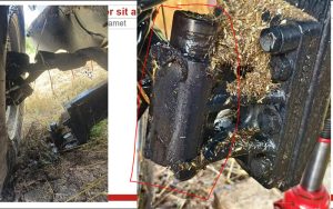
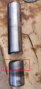
В июле 2024 года один из клиентов сообщил о поломке оси зерноуборочного комбайна во время работы в поле, что вызвало у него сильное беспокойство из-за невозможности бесперебойной уборки созревшего зерна. Первоначально он предположил, что причиной может быть некачественная сталь 40CrNiMoA, используемая в производстве вала, или несоответствие процесса термообработки требованиям. Мы получили их помощь, сломанная ось была проанализирована в первый раз, и было установлено, что проблема не в сырье и технологическом процессе, а в том, что он разработан заказчиком. В этом процессе не учитываются сложные условия работы оборудования. Также скрыты опасности односторонней усталости от воздействия силы. Требования заказчика к высокотемпературной термообработке приводят к высокой твердости сердечника, что легко приводит к его износу и поломке. После анализа мы предлагаем заменить первоначальную термообработку процессом индукционной закалки с улучшением качества и улучшением поверхности, что снижает общую твердость сердечника и повышает твердость внешней поверхности, обеспечивая износостойкость. Образец был отправлен заказчику в соответствии с предложенным процессом. Новый образец показал отличные результаты во втором полевом эксперименте. Мы получили положительные отзывы.
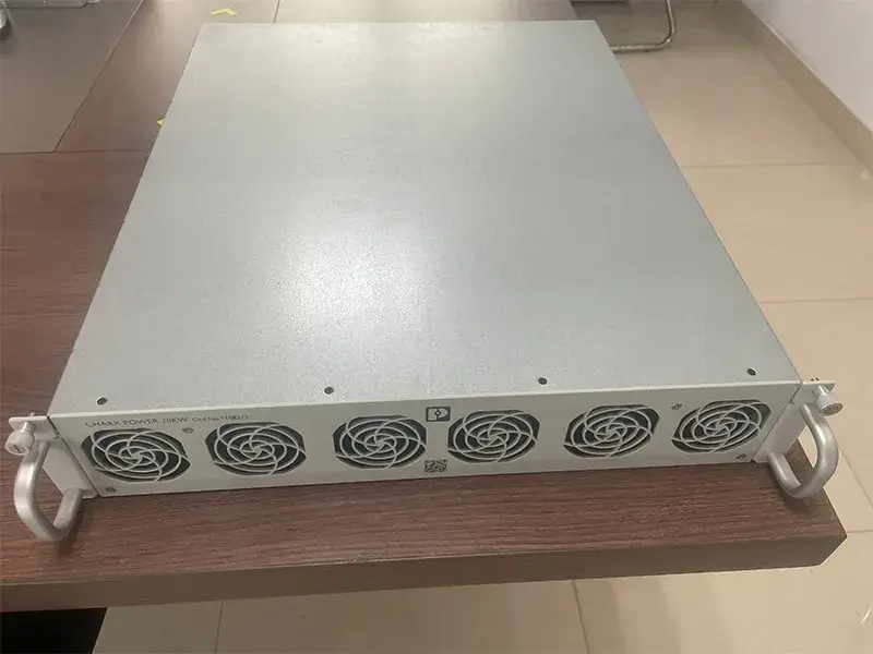
Процесс усовершенствования корпуса блока питания
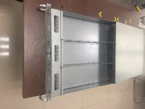
Один из немецких клиентов нашей компании столкнулся с трудностями на этапе проектирования комбинированного ящика. При использовании метода клепки он будет выступать за пределы плоскости, что повлияет на функциональность. При использовании метода сварки внешний вид не будет соответствовать требованиям, а стоимость будет высокой. После обращения к нам мы обнаружили успешный опыт работы над другими проектами. Мы можем отлично решить проблемы клиентов, используя двойные заклепки с плоской головкой и отверстия для крепления. Мы отправили образцы клиентам.
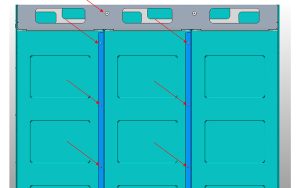
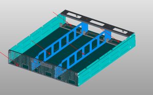
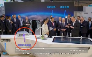
Они остались очень довольны и добились отличных результатов на выставке в Ганновере, получив единодушную похвалу!

Ваш партнер по комплексным решениям в сфере производства.
Ваш партнер по комплексным решениям в сфере производства.
От концепции до завершения – высочайшее качество проектирования для глобального успеха.
В компании ChuangKai мы устраняем сложности, связанные с поиском поставщиков из разных источников. Будучи вертикально интегрированным производителем, специализирующимся на ODM и OEM решениях, мы обеспечиваем бесперебойное производство высокоточных компонентов благодаря нашим комплексным возможностям:
Комплексные производственные услуги:
- Механическая обработка: фрезерование/токарная обработка на станках с ЧПУ, обработка на швейцарских станках.
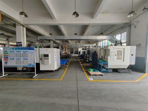
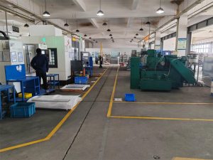
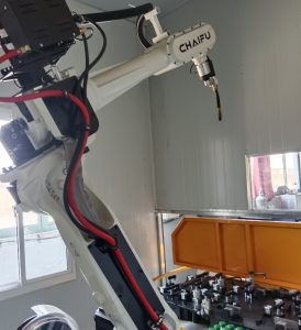
- Изготовление металлических конструкций: лазерная резка, гибка, сварка.
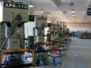
- Штамповка и формовка: штамповка с использованием прогрессивных штампов, глубокая вытяжка.
- Изготовление оснастки и пресс-форм: проектирование и производство штампов/пресс-форм на заказ.
- Обработка поверхности: порошковая покраска, покраска распылением.
- Сборка и тестирование: полная комплектация, проверка качества.
Преимущества ODM/OEM для вашего бизнеса:
Инновации в дизайне
Наша инженерная команда сотрудничает с вами для оптимизации конструкций с точки зрения технологичности производства, экономической эффективности и производительности, превращая концепции в готовые к выходу на рынок продукты.
Подотчетность из единого источника
Больше не нужно координировать работу более чем пяти поставщиков. Мы управляем всем рабочим процессом под одной крышей:
Проектирование → Создание прототипов → Изготовление оснастки → Закупка сырья → Производство → Отделка → Сборка → Логистика
Экономически эффективное производство
Вертикальная интеграция + оптимизация процессов = снижение затрат на 15-30% по сравнению с фрагментированными цепочками поставок.
| Скорость выхода на рынок |
Параллельное проектирование сокращает сроки выполнения на 40%. Соблюдайте сроки без ущерба для качества.
| Качественная встроенная конструкция |
Производственные процессы, сертифицированные по стандарту ISO, с цифровой прослеживаемостью. Доступна отчетность по PPAP, FAIR и CPK.
√ Отрасли, которые мы обслуживаем:
Автомобильная промышленность | Промышленное оборудование | Медицинские приборы | Возобновляемая энергия | Робототехника | Атомная энергетика
Почему клиенты со всего мира выбирают нас:
Решатели проблем: как, например, в случае с [учебным демонстрационным оборудованием], где мы заменили сварные узлы на цельные штампованные детали, что позволило устранить протечки и сократить расходы на 25%.
Масштабируемые мощности: поддержка от создания прототипов на этапе NPI до серийного производства объемом более 1 миллиона единиц.
Техническая гибкость: более 20 инженеров готовы решать сложные задачи, связанные с геометрическими допусками, жесткими допусками (±0,01 мм) и материалами.
→ Запросить бесплатный DFM-анализ
Загрузите свои чертежи/образцы. Наши инженеры определят возможности оптимизации затрат и эффективности в течение 48 часов.
Продукты

Часто задаваемые вопросы
В этом разделе даны ответы на часто задаваемые вопросы о нашей механической и электрической продукции, услугах и политике. Он поможет вам быстро найти информацию, не обращаясь в службу поддержки.
Наша главная сила заключается в интеграции всей производственной цепочки, от высокоточной обработки металла, прецизионной обработки листового металла, штамповки, проектирования и производства на заказ, профессиональной обработки поверхности методом напыления до окончательной сборки продукции, а также во внедрении превосходной системы управления качеством на протяжении всего процесса. Это означает, что клиентам не нужно координировать действия нескольких поставщиков для получения эффективных, скоординированных и стабильных услуг. Наш строгий контроль качества осуществляется на каждом этапе, гарантируя, что в конечном итоге поставляются не только детали или изделия, соответствующие требованиям, но и стабильные, надежные и высококачественные комплексные решения, эффективно помогающие клиентам сократить сроки поставки, снизить затраты и повысить эффективность цепочки поставок.
Изготовление нестандартных компонентов на заказ. Срок зависит от сложности изделия. Обычно срок поставки составляет от 2 до 4 недель.
25
Годы Опыт

















Связаться с нами
недавние статьи
недавние статьи
Нужны решения в области механики и электротехники, или есть вопросы? Свяжитесь с нами!
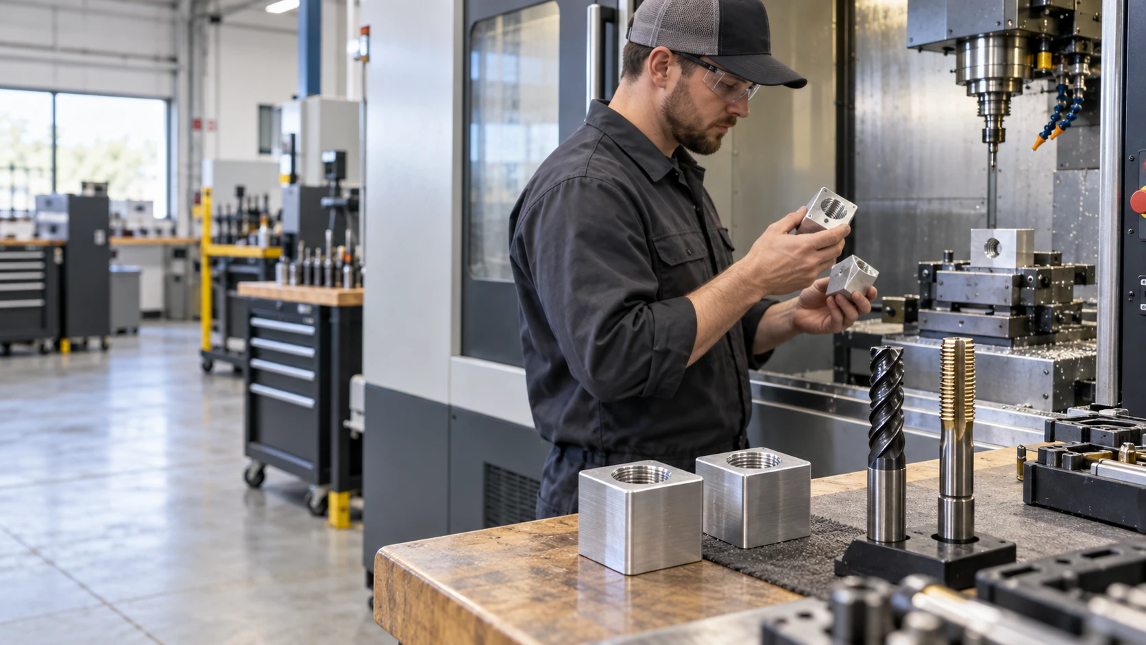
Tapping vs. Thread Milling for CNC-Machined OEM Parts: Choosing the Right Internal Thread Process
23
Октябрь
The choice between tapping and thread milling depends on the hole, material, thread specification, production quantity, machine capability, and cost of failure. Tapping is usually the faster route for repeat production of standard internal threads. Thread milling offers more control over thread size and fit, handles a wider range of diameters with fewer tools, and can reduce the consequence of a tool failure in a valuable part.
Neither process is universally better. A through-hole in a stable aluminum part may favor tapping, while a large thread, difficult material, expensive near-finished component, or close fit adjustment may justify thread milling. Blind-hole geometry and usable thread depth can change the answer again.
Tapping vs Thread Milling at a Glance
| Decision factor | Tapping | Thread milling |
| Cycle time | Often faster for standard repeated threads. | Usually longer because the tool follows a helical path. |
| Tool flexibility | One tap normally matches a specific size, pitch, and form. | One cutter may cover multiple diameters that share a compatible pitch and profile. |
| Fit adjustment | Limited after the tap and hole preparation are selected. | Tool-path offsets can adjust the finished thread within process limits. |
| Failure risk | A broken tap may be difficult to remove from the part. | A smaller cutter may be easier to recover from, but breakage can still damage the feature. |
| Machine need | Requires controlled feed and rotation appropriate to the tapping method. | Requires CNC helical interpolation, suitable control, rigidity, and access. |
How Each Process Cuts an Internal Thread
Both methods begin with a prepared hole, but their tool engagement is different. The drawing must specify the finished thread; the process planner then selects the pre-hole, tool, cutting data, and inspection route.
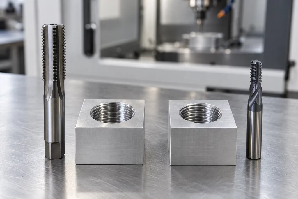
Tapping
A tap advances axially while its cutting edges or forming lobes create the complete thread profile. Because the tool engages around the circumference, torque, alignment, lubrication, chip control, and the prepared-hole diameter are important. Cut taps generate chips. Form taps displace suitable ductile material without chips, but they require a different hole size and should be approved for the material and specification.
Thread Milling
A thread mill rotates while the CNC moves it along a helical path. The cutter is smaller than the finished thread, so it engages a portion of the circumference at a time. The program controls diameter and direction, and suitable cutters can produce internal or external threads. The method needs enough bore access, tool clearance, machine interpolation, and stable workholding.
Choose by Hole Geometry
Through Holes
Through holes usually provide easier chip evacuation and fewer bottom-clearance constraints. For standard sizes and meaningful batch quantities, tapping often provides the most efficient cycle. A spiral-point cutting tap may push chips ahead through the opening when the material and application permit. Thread milling remains useful for large diameters, adjustable fits, mixed thread sizes, or parts where tool-breakage recovery influences the risk calculation.
Blind Holes
Blind holes need separate values for drilled depth, full thread depth, usable engagement, and bottom clearance. A tap has an incomplete lead before it produces full threads, and chips must have somewhere to go. Tap style, coolant delivery, chip evacuation, and reversal therefore matter. Thread milling can approach a shoulder with controlled axial positioning, but it still needs entry and exit clearance and cannot create usable thread beyond its programmed geometry. Do not specify “thread to bottom” without defining a manufacturable termination.
Choose by Material and Thread Specification
Material behavior affects torque, chips, tool wear, heat, and edge quality. Standard threads in machinable aluminum may favor tapping for speed, although chip packing or built-up edge still needs control. Tough stainless steels, high-temperature alloys, or expensive heat-treated parts may make the lower engagement and recovery advantages of thread milling more attractive. The supplier should confirm the exact alloy, hardness, and hole depth before choosing the route.
Thread size and form matter as much as material. Small standard threads may suit tapping, while larger diameters, special profiles, right- and left-hand variants, or adjustable fit classes can favor thread milling. A thread mill is not universal: its diameter, pitch capability, length, cutting form, and reach must match the feature.
Choose by Quantity and Cost of Failure
For a stable high-volume job, the shorter cycle of tapping can outweigh its lower flexibility. For prototypes and mixed families, thread milling may reduce the number of dedicated tools and allow diameter correction through offsets. The value of the workpiece also matters. Breaking a tap in an almost-complete housing can cost more than the saved cycle time; however, thread milling adds programming time and may use a more expensive cutter. Compare total route cost, not tool price alone.
Define the Thread Correctly on the Drawing
A process comparison cannot correct an incomplete specification. Use the same feature-based discipline applied to CNC machining tolerances, and include the following information:
- Thread standard and designation, nominal size, pitch or threads per inch, internal class or tolerance, and right- or left-hand direction.
- Through or blind condition, drilled depth, full thread depth, minimum usable engagement, entrance chamfer, and any bottom-clearance limit.
- Material grade and condition, heat treatment, coating or plating, quantity, critical datum relationships, and mating-fastener information.
- Inspection method, gauge standard, sampling level, first-article record, and any functional assembly test.
A complete CNC machining RFQ checklist also keeps model, drawing, revision, finish, and inspection assumptions consistent across bidders.
Verify the Sample and Production Route
Inspect the pre-hole as well as the finished thread. Confirm location, diameter, depth, chamfer, burr condition, and cleanliness. Use the specified GO and NO-GO gauges or another agreed method, then test the real mating fastener when assembly behavior matters. Record tool offsets and wear limits for thread milling, or torque, tap life, and chip-control checks for tapping. A first article should also confirm that coating, plating, or heat treatment does not invalidate the final fit.
Evaluate Supplier Capability Against the Part
CK Metal Tech publishes precision machining capabilities that include CNC milling, drilling, tapping, and related inspection resources. Its broader CNC machining services for precision metal parts provide the context for OEM process planning. The project review should still confirm whether tapping, thread milling, or another threading method is available and appropriate for the specific size, material, depth, tolerance, quantity, and inspection plan.
Заключение
Use tapping when a standard internal thread, suitable material, controlled hole, and repeat quantity make cycle time the priority. Consider thread milling when fit adjustment, large or varied sizes, difficult materials, blind-hole constraints, or the cost of a trapped broken tap changes the economics. The drawing and sample plan should make the choice verifiable rather than leaving it to habit.
Часто задаваемые вопросы
Is Thread Milling Always More Accurate Than Tapping
No. Either process can make acceptable threads when the machine, tool, hole preparation, setup, and inspection suit the requirement. Thread milling offers useful diameter adjustment, but it does not replace process control.
Which Process Is Better for Blind Holes
It depends on usable depth, bottom clearance, material, chip control, thread size, and quantity. A suitable tap can be efficient; thread milling can improve control where evacuation or failure consequences are difficult.
Can One Thread Mill Cut Several Thread Sizes
Sometimes. A cutter may cover multiple diameters with a compatible pitch and profile, within its diameter and reach limits. Confirm the tool manufacturer’s range and the required thread form.
How Should an Internal Thread Be Inspected
Use the drawing’s specified gauge or measurement method and sampling plan. GO and NO-GO gauges are common, but depth, location, surface condition, and functional assembly may also require verification.
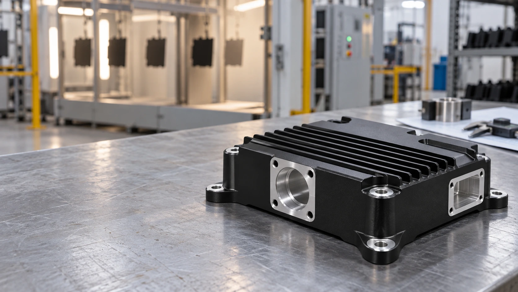
Can CNC-Machined Aluminum Housings Be Powder Coated? Thermal Interfaces, Fits, and Masking
22
Октябрь
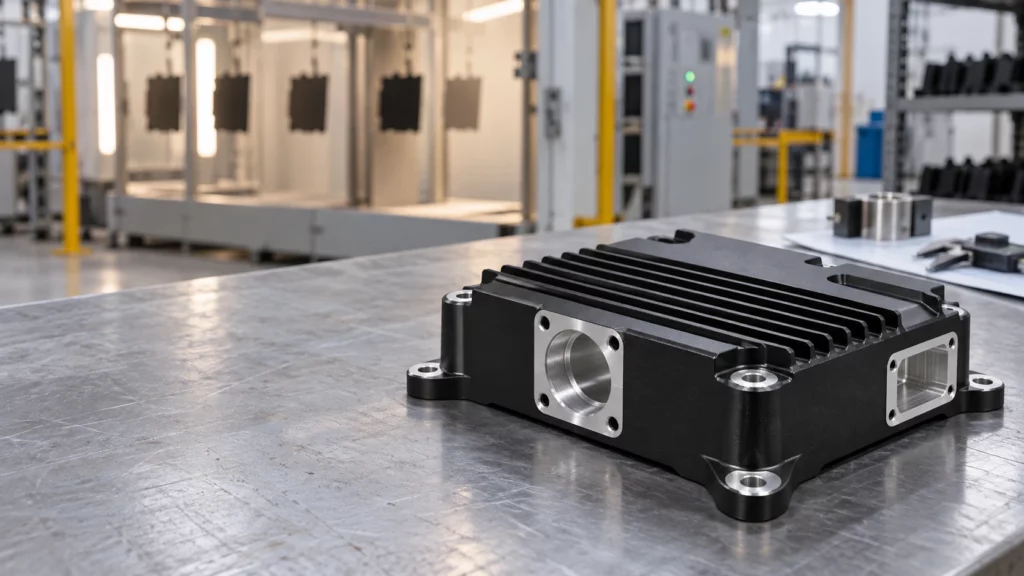
Can aluminum be powder coated after CNC machining? Yes, provided the drawing distinguishes cosmetic or protective surfaces from interfaces that must remain dimensionally, electrically, or thermally functional. A coating that performs well on an exterior wall can cause interference in a close fit, obstruct a thread, insulate a bonding point, or add thermal resistance at a heat-transfer joint.
The review should therefore start with the finished assembly, not the color. CK Metal Tech’s aluminum alloy cooling and shielding cover plate illustrates why this distinction matters: one machined component may combine an exterior cover, mounting holes, grooves, structural bosses, shielding functions, and heat-dissipation duties. Those surfaces should not automatically receive the same finish treatment.
Map Functional Surfaces Before Coating
Create a finish map on the controlled drawing or model. Identify coated faces, cosmetic faces, no-coat zones, and surfaces whose final dimensions apply after finishing. A generic note such as “powder coat black” does not tell the manufacturer how the housing must assemble or perform.
Surfaces Commonly Suitable for Coating
Exterior walls, non-mating covers, guards, and handling surfaces are typical candidates when the selected pretreatment and powder system match the aluminum alloy and service environment. Coating can support appearance and surface protection, but corrosion, chemical exposure, ultraviolet exposure, and cleaning requirements still need project-specific confirmation.
Surfaces That Often Need Masking
Common no-coat candidates include bearing or bushing seats, locating datums, close-tolerance bores, sliding rails, O-ring lands, sealing faces, connector grounds, threaded holes, fastener seats, and direct thermal contact pads. The decision is functional rather than categorical: a clearance hole may tolerate film build, while a locating hole with the same nominal diameter may not.
Mask Boundaries Need Their Own Definition
A no-coat note should show where the boundary begins, which direction the mask may shift, and whether a small transition band is acceptable. This is important around countersinks, spotfaces, grooves, stepped bores, gasket lands, and thermal pads. Masking has practical placement variation, and the cured edge may not form a perfectly sharp geometric line. Keep the boundary away from a sealing path or precision datum where possible. If the transition itself affects function, dimension it from a stable feature and include it in the first-article inspection plan.
How Powder Coat Changes Functional Interfaces
Powder coating adds material to the surfaces it covers. The actual build depends on the powder, application, grounding, part geometry, racking, and cure route, so the drawing should define the finished requirement instead of assuming a universal allowance.
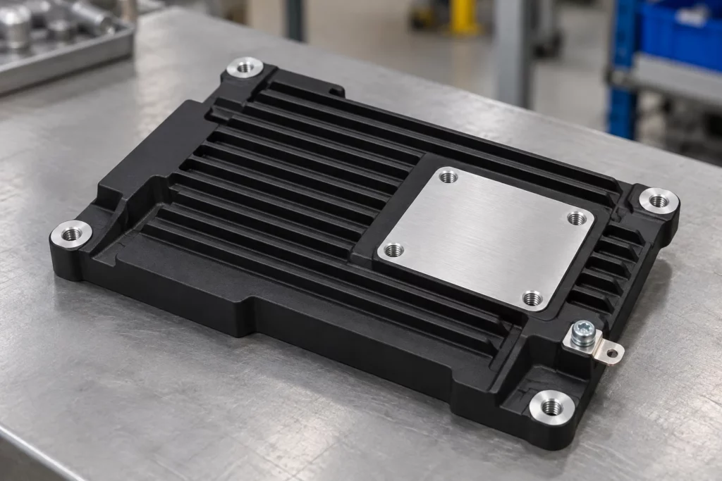
| Feature | Coating risk | Drawing or process control |
| Fits and threads | Film build reduces clearance and can obstruct engagement. | Mask, allow for the finish, or approve controlled post-coat machining. |
| Grounding points | The organic film can interrupt metal-to-metal electrical contact. | Mark bonding pads and define continuity or resistance verification. |
| Thermal interfaces | The coating and any trapped air can add resistance at a contact joint. | Keep direct-contact pads bare when required and define flatness, pressure, and interface material. |
| Sealing and datums | Build-up or an uneven mask edge can change seating and measurement references. | State whether dimensions apply before or after coating and locate mask boundaries. |
Fits and Threaded Features
Check each fit against its mating component and the finished-state tolerance. The same feature-level reasoning used for CNC machining tolerances applies after coating. Thread masks must protect the required diameter, lead-in, and usable depth. Forcing a screw through cured powder is not a controlled acceptance method because it can damage the finish and leave debris in the assembly.
Grounding and Thermal Contact
A designated grounding pad needs a clean boundary, a suitable fastener interface, and a defined verification method. Bare aluminum may also need a compatible protection strategy that preserves conductivity. For heat-transfer pads, evaluate coating together with contact area, surface flatness, clamping pressure, and any thermal interface material. A sample should be tested under representative heat load when temperature performance is critical.
Coordinate CNC Machining and Powder Coating as One Route
The safest sequence is established before chips are cut. Treat masking, finishing, and final inspection as part of the manufacturing plan rather than instructions added after machining.
- Review the current drawing, aluminum grade or approved alternative, functional interfaces, cosmetic zones, and operating environment.
- Machine the housing with any agreed allowance for surfaces controlled in the finished state; deburr edges without altering critical geometry.
- Clean and pretreat the part using a route compatible with the alloy, contamination condition, and specified coating system.
- Install plugs, caps, or high-temperature masking at the defined boundaries, then verify mask seating before spraying.
- Apply and cure the coating, remove masks cleanly, and inspect boundaries for lifting, chips, or unintended coverage.
- Complete only approved secondary machining or thread restoration, then clean the part and protect newly exposed aluminum as required.
An integrated review can connect the company’s precision machining capabilities with its powder coating service. The exact masking materials, post-coat operations, and inspection methods should still be confirmed for the part.
Verify the First Article Before Production
A first article should prove more than color and appearance. Use the actual mating components or representative gauges where possible, and record the drawing revision and coating specification used for approval.
- Dimensions: measure critical fits, datums, hole locations, and flatness in the state specified on the drawing.
- Assembly: install fasteners, covers, seals, rails, connectors, and locating features without forcing or finish damage.
- Electrical function: verify required bonding or shielding continuity at the specified contact points.
- Thermal function: check temperature performance under a representative load when the housing forms part of the heat path.
- Finish: inspect coverage, cure evidence, mask edges, handling damage, and cosmetic acceptance against an agreed reference.
Record nonconforming features separately. A part should not pass because its exterior looks uniform when a thread, bonding pad, thermal interface, or locating surface fails its own requirement.
What to Put in the Drawing and RFQ
Submit the 2D drawing and 3D model with material, quantity, coating system or performance requirement, color and texture, finished-state dimensions, no-coat zones, mask depth, thread callouts, grounding locations, thermal pads, inspection records, mating-part information, and sample approval criteria. Separate prototype quantity from expected production volume so the supplier can evaluate masking fixtures and process controls appropriately.
Заключение
CNC-machined aluminum housings can be powder coated successfully when the finish map protects the part’s working interfaces. The design should preserve required clearance, thread engagement, electrical bonding, and thermal contact, while the process plan should connect machining, pretreatment, masking, coating, and finished-state inspection.
Часто задаваемые вопросы
Should Every Threaded Hole Be Masked
No. Masking depends on thread function, fastener fit, engagement depth, and the approved finishing route. The drawing should identify which threads must remain coating-free and how they will be checked.
Can Powder Coat Be Allowed for in a Close Fit
Sometimes, but the designer and manufacturer must agree on the final clearance and whether the controlling dimension applies before or after coating. Do not rely on a generic film allowance.
Should a Thermal Contact Pad Remain Bare
Often it should when direct metal contact is part of the heat path. Confirm the complete joint, including flatness, contact pressure, interface material, corrosion protection, and the required thermal test.
Is Post Coating Machining Acceptable
It may be, if the operation is planned. Control chips, protect the surrounding finish, re-inspect dimensions, and define how newly exposed aluminum will be handled.
Request a Joint Machining and Coating Review
Send CK Metal Tech the drawing revision, alloy, quantity, mating-part details, coating requirements, no-coat zones, thermal duty, grounding needs, and inspection expectations. Use the request a joint machining and coating review route to confirm the manufacturing sequence before quotation.
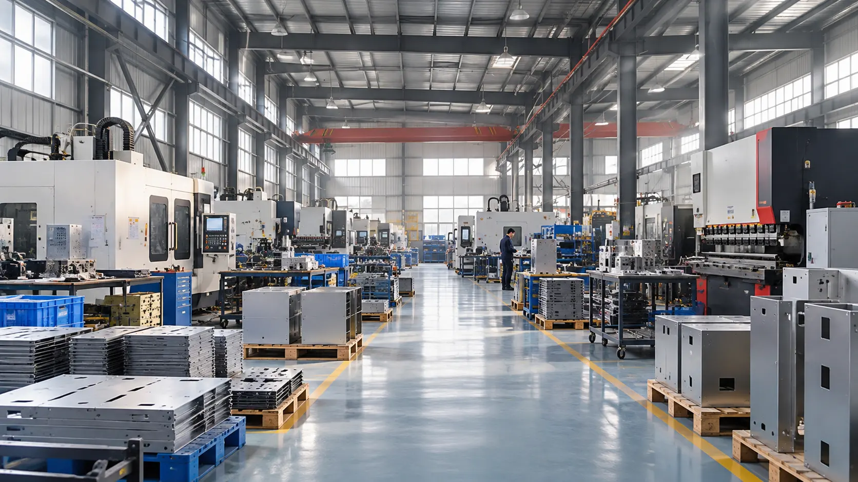
One Metal Supplier vs Multiple Vendors: How to Calculate Total Landed Cost
16
Октябрь
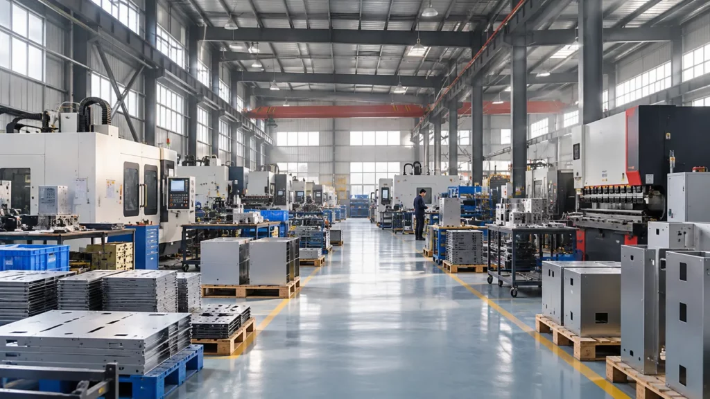
One metal supplier can reduce transfers between fabrication, finishing, and assembly, but supplier consolidation does not automatically lower total landed cost. Compare both routes at the same delivery destination, then add the buyer-side costs needed to turn delivered parts into accepted assemblies. Keep those layers separate: shipping and import charges belong in the landed-cost calculation; supplier administration, inventory, and integration costs belong in the broader sourcing decision.
For an OEM buying custom metal parts, this distinction prevents a lower piece price from hiding extra work. It also avoids calling every future operating expense a landed cost.
Define the Deliverable Before Comparing Vendors
Start with one controlled bill of materials and drawing revision. Specify material, finish, quantity, inspection criteria, packaging, destination, and assembly responsibility. A coated panel from one vendor cannot be compared directly with an assembled enclosure from another unless the missing operations are priced separately.
Distinguish process splitting from dual sourcing. Sending cutting to one shop and coating to another creates sequential handoffs. Qualifying two independent suppliers for the same finished assembly creates a backup route. These arrangements have different costs and continuity benefits; combining them under “multiple vendors” obscures the decision.
Calculate Total Landed Cost in Two Layers
The core shipment calculation is:
Landed cost = supplier invoices + separately charged tooling + packaging + freight + insurance + applicable duties, taxes, and clearance fees.
The International Trade Administration’s landed-cost guidance supports the product-plus-delivery approach. For metal parts, verify which charges are already included in each quotation. Add only costs outside the quoted scope, and use the same receiving location.
Then calculate a separate management metric:
Sourcing comparison cost = landed cost + buyer assembly and inspection + supplier administration + inventory carrying cost + evidence-based quality and disruption allowances.
This second formula is a purchasing decision tool, not a customs valuation or accounting rule. It does not include equipment operating costs over the product’s lifetime. Keep recoverable taxes and other accounting treatments identifiable for finance review rather than treating every cash payment as a permanent expense.
Normalize Quotes and Allocate Shared Charges
Use the same currency, demand period, release size, and named delivery point. Record the delivery term and which party pays each freight leg. A quote that includes shipping can appear expensive beside a factory-gate quote until the missing freight is added.
For international purchases, ask a qualified broker to verify classification, origin, applicable charges, and the relevant shipment date. Do not copy a tariff percentage from another part or last year’s order.
Allocate shared freight across a mixed shipment using a defensible driver, such as chargeable weight or occupied volume. Allocate tooling over the realistically committed program quantity, with tooling ownership shown separately. Show first-order and repeat-order costs independently; an optimistic lifetime volume can conceal a costly launch.
A Worked Example for One Thousand Assemblies
The following figures are hypothetical USD amounts, not CK Metal Tech quotations or tariff estimates. Both routes ultimately provide 1,000 accepted assemblies. The single supplier includes assembly in its invoice; the split route requires more buyer assembly work. Charges already included in supplier invoices are excluded from the other rows.
| Cost category | One supplier | Multiple vendors |
| Supplier invoices | $40,000 | $37,000 |
| Tooling and setup | $3,000 | $2,200 |
| Packaging freight and insurance | $1,800 | $3,300 |
| Illustrative import and clearance charges | $1,500 | $1,500 |
| Core landed cost | $46,300 | $44,000 |
| Buyer assembly and inspection | $800 | $3,300 |
| Supplier administration | $400 | $1,200 |
| Inventory carrying cost | $600 | $1,100 |
| Expected quality and rework allowance | $600 | $1,800 |
| Sourcing comparison total | $48,700 | $51,400 |
| Cost per accepted assembly | $48.70 | $51.40 |
Multiple vendors win the core landed-cost comparison by $2,300. After buyer-side costs are included, one supplier is lower by $2,700. This result follows the stated assumptions; it does not prove that consolidation is generally cheaper.
The decision changes if the split route reduces internal assembly effort, avoids quality losses, or provides a valuable qualified backup. Replace every allowance with program evidence before using this example for an award decision.
Measure Handoffs Without Double Counting
Map the route from cutting and forming through machining, coating, final inspection, and packing. Sheet metal fabrication may involve several linked operations, so track the transfers between them rather than counting suppliers alone.
For each handoff, record transport, protective packaging, receiving inspection, queue time, and revision-control responsibility. Estimate internal work from hours multiplied by an approved labor rate. Distinguish cash savings from staff capacity released: fewer purchase orders do not necessarily reduce payroll.
Estimate inventory carrying cost from average inventory value, the approved annual carrying rate, and the time period. Use historical rework and expedite costs where available. For a new program, show low, expected, and high cases rather than inventing a precise failure probability.
Avoid charging the same loss twice. If rejected units already reduce the accepted-unit denominator, check whether a separate scrap allowance repeats that loss. Likewise, do not add replacement freight when it is already included in a rework estimate.
Choose the Route and Test Its Weak Points
One supplier is attractive when interfaces dominate the program: welded frames must match machined brackets, coating boundaries affect fit, and completed assemblies require a coordinated release. Multiple vendors may be preferable when a process needs specialist qualification, capacity is constrained, or a genuinely independent backup is essential.
A backup is only useful if drawings, tooling access, qualification status, and available capacity make it executable. Two suppliers sharing the same critical subcontractor may still have a common interruption risk. Keep continuity requirements visible beside the cost comparison.
Test the decision against smaller releases, a rejected batch, an engineering change, and an expedited shipment. If the winner changes under a small assumption adjustment, resolve that uncertainty before committing the production route.
Request a Comparable Metal Manufacturing Quote
CK Metal Tech combines sheet metal processing, machining, stamping, powder coating, painting, and precision-component assembly. Review its metal manufacturing and assembly capabilities against the proposed route; process breadth alone does not establish capacity or suitability for a particular program.
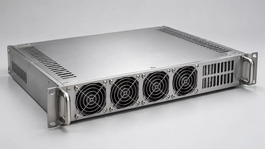
Send the BOM, controlled drawings, quantities, destination, finish requirements, and acceptance plan. Ask CK Metal Tech to separate tooling from recurring prices and identify subcontracted operations, excluded services, and packing assumptions. Give alternative vendors the same package.
Заключение
Choose the sourcing route using both delivered cost and the work required to obtain accepted assemblies. A transparent comparison can show that multiple vendors win on landed cost while one supplier wins after integration costs, or the reverse. Award the route whose cost assumptions and continuity requirements can be verified.
Часто задаваемые вопросы
Is one metal supplier always cheaper
No. Consolidation may reduce transfers and administration, while multiple vendors can provide specialist capability or backup capacity. Compare equivalent outputs and documented costs.
Is total landed cost the same as total cost of ownership
No. Landed cost addresses acquisition and delivery. Ownership cost extends into use, maintenance, and disposal. Buyer integration costs should remain a clearly labeled comparison layer.
How should tooling be included
Show the initial tooling payment separately, then allocate it across a defensible committed quantity for the unit comparison. Record ownership, maintenance responsibility, and repeat-order assumptions.
Should supplier management time count as a saving
Include it when comparing resource demand, but distinguish released staff capacity from actual cash savings. Use measured hours and an approved rate.
Request a Sourcing Route Review
Share the current drawings, BOM, delivery location, release schedule, and assembly scope with CK Metal Tech. Request a sourcing-route review to clarify included operations and compare the assumptions behind each quotation.