ЧУАНКАЙ

а я л а н д

Загрузка

     
дом // блог

блог

Powder Coating Defects on Sheet Metal How to Prevent Edge Rust and Thread Build-Up


Powder Coating Defects on Sheet Metal How to Prevent Edge Rust and Thread Build-Up

Powder coating defects on sheet metal are often most costly when they affect function rather than appearance. A panel may look acceptable across its flat surfaces while rust begins at exposed edges, or a threaded hole that passed inspection before finishing may no longer accept its fastener after coating. These failures have different immediate causes, but both point to the same purchasing lesson: edge condition, surface preparation, masking, coating requirements, assembly interfaces, and inspection should be defined before the parts enter production.

Why Do Powder-Coated Sheet Metal Edges Rust First?

Sharp Edges Can Receive Less Effective Coating Coverage

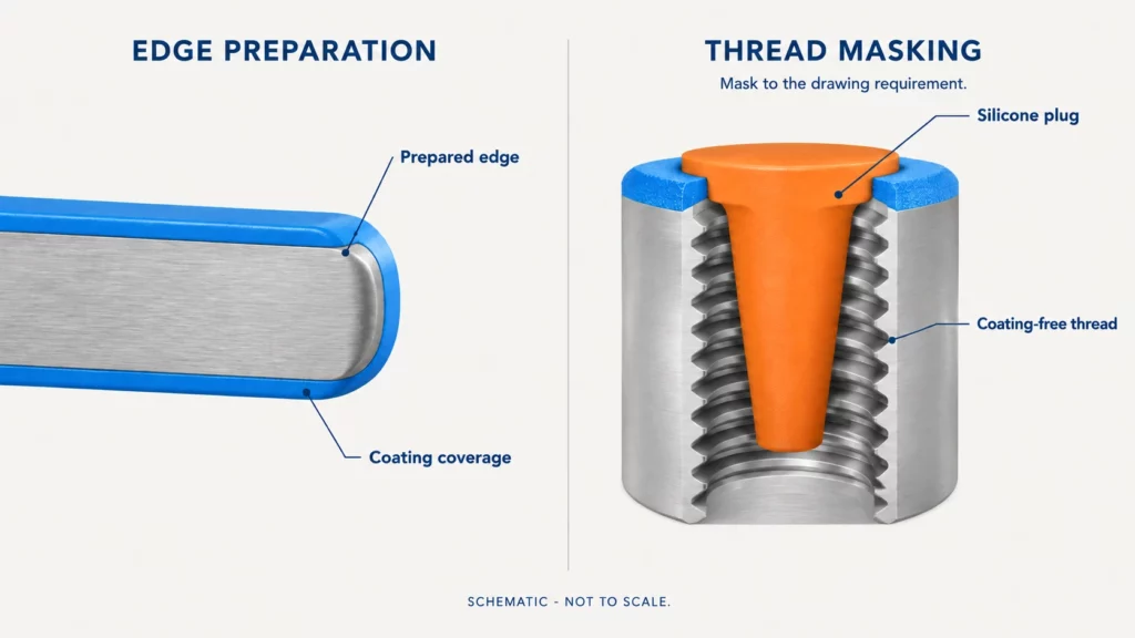
A sharp edge is not the same coating surface as a broad flat panel. The Powder Coating Institute defines edge coverage as a powder coating’s ability to flow over, build on, and adhere to sharp corners, angles, and edges. Coating behavior at those locations therefore deserves separate attention during design and inspection.

This helps explain a common failure pattern: the main panel remains coated while rust appears first along a cut or sharply formed edge. Technical guidance from a major powder-coating manufacturer also notes that sharp edges can retain less coating than the surrounding surface, reducing corrosion protection at those locations.

When only the edges are failing, engineers should inspect the edge geometry, burr condition, surface preparation, local film condition, and any damage after coating. Laser-cut, punched, sheared, or ground edges should not automatically receive identical preparation because their actual condition may vary.

The next action is not simply to specify “more powder.” Determine whether the weak point is created by fabrication, preparation, the coating system, or post-coating damage.

Rule Out Pretreatment, Contamination, and Handling Damage

Edge rust should not automatically be blamed on edge coverage. If corrosion also appears on broad surfaces, around welds, or beneath apparently intact coating, the investigation should widen.

Oil, oxidation, welding residue, burrs, and uneven surface conditions can affect the final finish. CK Metal Tech’s existing powder coating for sheet metal parts guide places cleaning and surface conditioning before coating and specifically identifies contamination, rust, weld residue, and sharp burrs as issues that should be reviewed.

Timing also matters. If parts leave production in acceptable condition but develop damage after packing, transport, installation, or assembly, examine impact and abrasion at edges and corners. Coating that has been mechanically damaged exposes a different root cause from an edge that never received sufficient protection. For larger housings and frames, powder coating handling and batch production should therefore be considered as part of the defect investigation rather than treating the coating booth as the only possible source.

How to Prevent Edge Rust Before Powder Coating

Treat Edge Condition as a Sheet Metal DFM Requirement

Edge-rust prevention starts during sheet metal fabrication. A drawing may carefully specify hole position, bend angle, and overall dimensions while saying nothing about an environmentally exposed cut edge.

For exposed covers, cabinets, frames, or brackets, determine which edges are functionally or environmentally critical. These may justify specific deburring, edge finishing, or other preparation requirements before coating. Internal edges that are inaccessible and noncritical should not automatically receive the same processing; unnecessary finishing adds manufacturing cost without necessarily improving function.

A practical DFM review should ask:

  • Will this edge be exposed to moisture, handling, or frequent contact?
  • Does the fabrication method leave a burr or unusually sharp transition?
  • Is the edge visible after assembly?
  • Does the corrosion requirement apply equally to edges and large surfaces?
  • Is the requirement clearly shown on the latest drawing?

The objective is not to apply one universal edge radius. The appropriate edge condition depends on material, geometry, fabrication process, coating system, operating environment, and customer specification.

Match Corrosion Protection to the Operating Environment

A powder-coated indoor cabinet and an outdoor equipment housing should not be specified from the same assumptions. Humidity, chemicals, cleaning, condensation, physical handling, substrate material, and expected service environment all influence the corrosion strategy.

Where corrosion exposure is more demanding, the coating supplier may need to evaluate pretreatment, primer, coating chemistry, or a system designed for stronger edge performance. Some commercial corrosion-protection powder systems are specifically designed around improved edge coverage, illustrating why the coating system has to be selected against the application rather than only by color and texture.

If a project requires a corrosion test, define the applicable method and acceptance requirement in the specification or RFQ. Do not assume that one salt-spray duration, primer system, or coating thickness applies to every powder-coated sheet metal part.

Why Does Powder Coating Build Up in Threaded Holes?

Coating Build-Up Can Turn a Good Thread Into an Assembly Failure

Powder coating on threads creates a different problem from edge rust. A coating layer that is harmless on a large panel can interfere with thread engagement, a precision hole, an electrical contact surface, or another fit-sensitive feature.

This is why a tapped hole can meet its machining requirement before coating but cause difficulty when a screw is installed afterward. CK Metal Tech’s published coating guidance specifically identifies threaded holes, grounding points, bearing surfaces, PEM fasteners, assembly contact surfaces, and tolerance-sensitive slots as areas requiring review before coating.

When a bolt does not start after powder coating, first establish whether the thread was acceptable before finishing. Then inspect where coating accumulated and whether the drawing identified the thread as a no-coat feature.

Repeatedly scraping or chasing threads after coating may correct individual parts, but it also creates rework and can damage the coating boundary. In repeat production, prevention is generally easier to control than relying on manual cleanup after curing.

Decide Which Threads and Functional Surfaces Must Remain Coating-Free

Not every hole or threaded feature has the same function. An internal tapped hole, external threaded stud, grounding connection, bearing surface, mating flange, and ordinary clearance hole should be reviewed separately.

Industrial masking guidance identifies threads, studs, ports, sealing surfaces, grounding points, and other fit-critical areas as typical locations that may need protection from coating.

Before releasing the drawing, ask:

  • Does coating interfere with fastener engagement?
  • Must the surface provide electrical continuity?
  • Is the area part of a precision fit or mating interface?
  • Does the coating boundary affect sealing or assembly?
  • Does the supplier know exactly how much of the feature must remain bare?

A vague instruction such as “mask threads” may still create disagreement if the required masking depth, surrounding bare area, or boundary is unclear.

How to Mask Threads and Functional Surfaces Before Powder Coating

Match Plugs, Caps, and Tape to the Feature Geometry

The masking method should follow the geometry and function of the no-coat area rather than using one method for every feature.

Feature Main risk Masking approach to evaluate Buyer should confirm
Internal tapped hole Coating inside thread Plug Diameter, depth, lead-in
External threaded stud Coated external thread Cap Required mask length
Grounding hole Loss of conductive contact Plug/cap with surrounding mask Required bare contact area
Flat mating surface Assembly interference Tape or disc Boundary and functional tolerance

Industrial masking suppliers commonly separate plugs for holes, ports, bores, and internal threads from caps used on studs and external projections, while tapes and discs are used to define flat no-coat areas.

Blind holes, through holes, countersunk features, irregular contours, and high-volume recurring parts may require different solutions. Buyers should therefore specify the functional no-coat requirement and let the masking method be reviewed against the actual geometry and production process.

Plan PEM Hardware and Secondary Thread Work Before Coating

PEM hardware, threaded inserts, studs, and secondary tapping should be considered as part of the manufacturing sequence rather than added as an afterthought.

Installing hardware before coating may create masking requirements around the fastener and adjacent contact area. Installing it afterward may change handling or assembly requirements. Post-coat thread chasing may remove unwanted coating but can also add labor and disturb the finished boundary.

The appropriate sequence depends on part design, hardware type, coating specification, assembly method, and production quantity. Before sampling, fabrication, finishing, and assembly requirements should be reviewed together so the RFQ clearly identifies which features are installed, machined, masked, or inspected at each stage.

How to Inspect Powder-Coated Parts Before Batch Production

Inspect Edge Condition, Thread Function, and Assembly Fit Together

Visual appearance alone does not prove that a coated part is ready for production. Inspection should follow the reasons the coating is specified.

Check exposed edges for coating continuity and damage. Verify critical threaded features using the inspection method defined for the project. Confirm masked areas and coating boundaries. Where fit matters, assemble the actual mating fastener or component rather than relying only on the uncoated dimensional report.

First-article review is particularly useful when a new drawing combines tight interfaces, masked features, cosmetic requirements, and corrosion exposure. Batch inspection should then retain the checks that protect those critical functions.

Handling remains part of this review. A finished enclosure can pass dimensional and cosmetic inspection and still be damaged during packing or transfer. CK’s published finishing guidance treats packaging and edge protection as part of the overall coating workflow rather than a separate purchasing issue.

Define Corrosion Validation From the Project Requirement

Corrosion validation should follow the intended application and customer specification. A project exposed to outdoor moisture may require a different validation plan from an indoor machine cover.

Specify the test method, specimen condition, coating system, acceptance criteria, and relevant surfaces when formal corrosion verification is required. The Powder Coating Institute distinguishes corrosion, edge coverage, pretreatment, and creepage as separate technical concepts, reinforcing the need to define what the project is actually evaluating.

Avoid copying a test duration or acceptance limit from an unrelated product. The correct requirement may vary with substrate, pretreatment, coating system, environment, geometry, and customer standard.


Powder coating defect prevention matrix for sheet metal showing edge rust, thread build-up, masking, inspection, and RFQ requirements

What Should OEM Buyers Put in a Powder Coating RFQ?

A useful RFQ should make functional coating requirements visible before the supplier prices the work. Include the base material, drawing revision, application environment, exposed critical edges, threaded holes and studs, PEM hardware, grounding points, mating surfaces, no-coat zones, cosmetic surfaces, corrosion expectations, coating specification if defined, inspection requirements, quantity, and packaging needs.

CK’s existing guidance similarly recommends defining material, masked areas, corrosion expectations, cosmetic surfaces, coating requirements, and packaging before production.

When problems have already occurred, send defect photographs, the affected drawing revision, mating hardware if relevant, and information on when the rust or assembly problem appeared. That gives the supplier a better basis for root-cause review than a request to “improve coating quality.”

Как выбрать поставщика услуг по изготовлению изделий из листового металла и порошковой покраске

Look Beyond the Powder Coating Booth

Edge rust and thread build-up illustrate why finishing quality cannot be separated completely from fabrication quality. The edge may originate in laser cutting, punching, bending, grinding, or welding; the blocked thread may originate in an incomplete drawing or masking plan.

A supplier should therefore be able to review the connected route from fabrication through finishing, inspection, assembly fit, and packaging. CK Metal Tech publicly lists sheet metal cutting, punching, bending, riveting and welding alongside powder coating and painting capabilities. Buyers considering sheet metal fabrication and powder coating should ask how critical edges, threads, no-coat areas, and finished assemblies will be controlled—not simply whether a powder coating line is available.

CK Metal Tech also describes powder coating as part of its broader интегрированные возможности высокоточного металлообработки, allowing fabrication and surface-finish requirements to be reviewed within the same manufacturing scope. The project drawing and acceptance criteria should still determine whether that capability matches the application.

Заключение

Edge rust and thread build-up require different immediate corrections, but both are easier to prevent when fabrication, preparation, masking, coating, inspection, and assembly are treated as one manufacturing plan. Define critical edges and no-coat features on the drawing, match corrosion requirements to the operating environment, and validate coated parts in their final functional condition.

For a defect or new-project review, prepare the drawing, material, application environment, affected dimensions or threads, coating requirement, target quantity, mating hardware, and any defect photographs or samples. Buyers can свяжитесь с CK Metal Tech with these details for a manufacturability and finishing review.

FAQs About Powder Coating Edge Rust and Thread Build-Up

Why does powder coating rust first on sharp edges?

Sharp edges can receive different coating buildup from broad flat surfaces, making edge coverage an important corrosion consideration. Inspect the edge condition, preparation, local coating, environment, and possible handling damage before assigning the root cause.

Should threaded holes be masked before powder coating?

Fit-critical threaded holes should be reviewed as potential no-coat areas. Plugs are commonly used to protect holes and internal threads, but the correct masking requirement depends on thread function, geometry, coating specification, and assembly needs.

Can threads be tapped again after powder coating?

Threads can be reworked in some manufacturing routes, but post-coat tapping or thread chasing adds another operation and can disturb coating at the boundary. For repeat production, determine whether masking or a planned secondary operation provides the more controlled process.

How do I keep powder coating off grounding and mating surfaces?

Identify the required bare area on the drawing and choose masking according to geometry. Plugs or caps can protect holes and studs, while tapes or discs can define flat no-coat zones; specialized masking can also create an uncoated area around grounding features.

4th Сентябрь 2026

CNC Machining RFQ Checklist What to Send for an Accurate Production Quote


CNC Machining RFQ Checklist What to Send for an Accurate Production Quote

A CNC machining RFQ can produce very different prices when suppliers are working from different drawing revisions, material assumptions, tolerances, quantities, finishes, or inspection scopes. For a production quote, the goal is not simply to receive a price. It is to give each supplier enough controlled information to quote the same finished part under the same assumptions. A complete CNC machining RFQ checklist therefore needs to cover files, technical requirements, production demand, secondary operations, quality requirements, and quotation exclusions.

What Does a CNC Machining Supplier Need for an Accurate Quote?

Separate the Minimum RFQ Package From Project-Specific Requirements

A useful CNC machining quote package should first identify the part, current revision, geometry, material, quantity, critical tolerances, and required finished condition. If any of these are unknown, state that clearly instead of allowing each supplier to make a different assumption.

A practical minimum package usually includes:

  • Current part number and revision
  • 3D CAD model
  • Controlled 2D drawing when required
  • Material specification
  • Quote quantity
  • Critical dimensions and tolerances
  • Threads and functional features
  • Heat treatment or surface finish, if applicable

Production projects may also require annual demand, inspection documentation, packaging, mating-component information, marking, or special handling. The requirement depends on the application rather than a universal checklist.

What CAD Files and Drawings Should You Send for a CNC Machining Quote?

When Is a STEP File Enough—and When Do You Need a 2D Drawing?

A STEP model is useful for communicating part geometry. STEP is part of the ISO 10303 family for exchanging product data between computer systems. However, geometry alone may not communicate all manufacturing requirements.

A simple prototype with noncritical dimensions may sometimes be evaluated mainly from the 3D model. A production component with GD&T, special threads, surface roughness requirements, controlled datums, heat treatment, or inspection notes generally needs additional product-definition information.

ASME Y14.5 describes GD&T as a standardized language for communicating design requirements on engineering drawings, digital models, and related documents. The purchasing question is therefore not “Is STEP enough?” in isolation, but “Does the RFQ clearly communicate everything that controls form, fit, function, and inspection?”

Keep Part Numbers, File Names, and Revisions Consistent

Revision mismatch is one of the easiest ways to make CNC quotations incomparable. If one supplier quotes Rev B while another receives Rev C, differences in geometry, tolerance, or finishing can appear as price differences.

Use the same part number, model revision, drawing revision, quantity, and specification package for every bidder. When engineering changes occur, identify which files have been superseded and request confirmation that the revised quotation is based on the latest package.

For repeat production, this discipline becomes even more important because the quoted process, inspection plan, fixture assumptions, and secondary operations may all depend on the released revision.

How Should You Specify Material and Production Quantity?

Specify the Exact Material Requirement—and Whether Alternatives Are Allowed

“Aluminum” or “stainless steel” may be insufficient for an accurate production quote. When the application requires a particular grade, condition, temper, hardness, or material specification, put it on the drawing or RFQ.

If alternatives are acceptable, state that explicitly. A supplier should not have to decide independently whether a different alloy or stock condition is functionally equivalent.

Also identify any material-related secondary requirements, such as heat treatment or hardness, when they form part of the finished-part specification. These requirements can affect process planning and should not be added only after the machining price has been approved.

Separate Prototype Quantity From Repeat Production Demand

A prototype quote and a production CNC machining quote answer different purchasing questions.

For a prototype, the supplier may focus on rapid programming, readily available stock, flexible workholding, and a small quantity. Repeat production may justify different fixtures, tooling, batch planning, inspection methods, or machining routes.

Instead of sending only “Qty: 20,” consider providing:

  • Current RFQ quantity
  • Prototype or pilot quantity, if relevant
  • Typical production release quantity
  • Estimated annual demand, when reasonably known

These figures do not guarantee a particular price. They give the supplier enough context to propose a production route that fits expected demand rather than treating every order as a one-off job.

Which Tolerances and Functional Features Should Be Highlighted?

Highlight CTQ Features Instead of Tightening Every Dimension

Not every dimension controls part function. Bearing locations, alignment datums, sealing surfaces, mating interfaces, runout requirements, and precision bores may require closer control than clearance holes or nonfunctional external surfaces.

Blanket tight tolerances can add machining and inspection burden without improving the assembly. Instead, identify critical-to-quality or critical-to-function features and communicate the design intent clearly.

ASME notes that GD&T provides a common language for specifying and interpreting functional geometric requirements. Before the RFQ is issued, engineering and purchasing should agree on which characteristics genuinely require special control.

Specify Threads, Fits, Surface Finish, and Assembly-Critical Details

Thread size, pitch, depth, class or fit requirements, critical bore relationships, surface roughness, chamfers, burr-sensitive edges, and assembly interfaces can change the manufacturing route.

If a machined surface mates with a bearing, seal, another precision component, or a finished assembly, state that function when it helps the supplier understand the requirement. Do not rely on a CAD model to communicate a characteristic that exists only as manufacturing intent.

CK Metal Tech’s machining content similarly identifies material, key dimensions, tolerances, surface finish, heat treatment, threads, chamfers, inspection methods, and packaging as items to review before repeat CNC production.

What Secondary Operations Must Be Included Before Quotation?

Define the Complete Finished-Part Scope, Not Just the Machining Scope

A machining-only price is not an accurate finished-part quote if the component later requires grinding, heat treatment, anodizing, plating, coating, marking, cleaning, or assembly.

State required secondary processes before comparing bids. Also identify masked areas, surfaces affected by post-treatment buildup, or dimensions that must be controlled after heat treatment or finishing.

This is where OEM precision metal manufacturing becomes relevant: buyers should understand whether a quote covers only CNC cutting or the complete process route through finishing and other required operations. CK Metal Tech publicly lists CNC milling and turning alongside Swiss machining, surface treatment, sheet-metal fabrication, stamping, and assembly within its OEM/ODM manufacturing scope.

What Inspection and Documentation Requirements Should Be Defined?

Ask for the Quality Evidence the Project Actually Requires

Inspection requirements should be known before pricing, particularly when the buyer requires records beyond normal production inspection.

A project may call for measurements of selected CTQ features, dimensional reports, CMM-based inspection, material documentation, or other customer-defined evidence. The appropriate scope depends on the drawing, industry, risk, and purchasing specification.

Do not assume every document is automatically included. Requiring additional reporting after quotation can change inspection time and administrative scope. CK Metal Tech publicly lists machining and inspection-related resources as part of its broader интегрированные возможности высокоточного металлообработки, but the exact documentation for a specific RFQ should still be defined by the project.

What Makes a Production CNC RFQ Different From a Prototype RFQ?

Add Repeat-Production Controls, Release Pattern, and Packaging Requirements

A successful prototype proves that a part can be made; it does not automatically define how it should be purchased repeatedly.

For production, confirm the released revision, normal batch quantity, anticipated demand, critical inspection characteristics, secondary operations, and packaging requirements. Precision shafts, finished surfaces, threads, or cosmetic components may require packaging that protects the characteristics already paid for during manufacturing.

Production RFQs should also distinguish one-time costs from recurring part costs where applicable. This makes later purchase orders easier to evaluate and reduces the risk that a low prototype price is mistaken for a stable production price.


CNC machining production RFQ checklist showing CAD files, drawings, material, tolerances, quantity, inspection, finishing, and quote risks

How to Compare CNC Machining Quotes From Multiple Suppliers

Compare Scope and Assumptions Before Unit Price

The lowest unit price is meaningful only when suppliers have quoted the same scope.

Quote Check Supplier A Supplier B Supplier C
Same drawing revision
Same material specification
Same production quantity
Critical tolerances included
Secondary processes included
Inspection/documentation included
Packaging included
Setup/NRE clearly identified
Delivery assumptions defined
Exclusions documented

If one quotation includes grinding, finishing, inspection, and packaging while another covers machining only, the two unit prices are not equivalent.

This is also where комплексное производство высокоточных металлических изделий can affect sourcing decisions. When machining, finishing, fabrication, or assembly are split among suppliers, purchasing teams should compare the completed manufacturing route and supplier handoffs rather than one operation in isolation. CK Metal Tech’s existing sourcing guidance discusses the additional coordination, inspection, and responsibility created when processes are fragmented across suppliers.

How to Choose a CNC Machining Supplier for Repeat Production

Evaluate DFM, Process Planning, Inspection, and Secondary Capability

A production supplier should be able to explain how the drawing will be manufactured, not simply confirm that it can be made.

Ask which features drive the process, how the workpiece will be held, which dimensions require special inspection, what secondary operations are included, and whether prototype and production use the same route. The answers matter when comparing услуги по прецизионной обработке на станках с ЧПУ for repeat orders.

CK Metal Tech lists CNC lathes, vertical machining centers, Swiss machining, cylindrical and centerless grinding, thread-processing equipment, and related machining resources. The company also connects machining with other manufacturing and finishing processes where a finished component requires more than one operation.

The RFQ should still determine suitability. Machine availability alone does not prove that a supplier is the correct choice for a particular geometry, tolerance, material, quantity, or quality requirement.

Final CNC Machining Production RFQ Checklist

Before sending a request for quotation, confirm:

  • Part number and current revision
  • STEP or other agreed 3D model
  • Controlled 2D drawing where required
  • Material grade and condition
  • Current RFQ quantity
  • Prototype, pilot, or production status
  • Expected repeat quantity or annual demand if relevant
  • Critical dimensional tolerances
  • GD&T where required
  • Threads and fits
  • Surface roughness and functional surfaces
  • Heat treatment
  • Plating, anodizing, coating, or other finish
  • Masking or no-finish zones
  • Inspection scope
  • Required quality documentation
  • Packaging requirements
  • Target delivery requirement
  • Approved alternatives or unresolved engineering questions

Заключение

An accurate CNC machining production quote starts with controlled files, an exact material requirement, realistic quantities, clearly identified CTQ features, complete secondary operations, and a defined quality scope. Give every supplier the same information before comparing prices.

For a production review, prepare the drawing, 3D model, revision, material, quantities, tolerances, finish, inspection requirements, and any mating or application details that affect the part. Buyers can свяжитесь с CK Metal Tech with that package for manufacturability review and quotation.

FAQs About CNC Machining RFQs

Is a STEP file enough for a CNC machining quote?

It may be sufficient for evaluating simple geometry or an early estimate, but a production part may also require a controlled drawing to communicate tolerances, GD&T, threads, finishes, notes, and inspection requirements. STEP is an established ISO 10303 product-data exchange format, but the RFQ must still communicate the complete manufacturing intent.

What files should I send for a CNC machining production quote?

Send the current 3D model and controlled drawing when applicable, with matching part numbers and revisions. Include material, quantity, critical tolerances, threads, finishing, secondary operations, inspection requirements, and other project-specific information.

Should I include annual volume in a CNC machining RFQ?

For repeat production, yes when a realistic estimate is available. State the immediate quote quantity separately from expected release quantities or annual demand so the supplier can evaluate both the current order and recurring production requirements.

Why are quotes for the same CNC part so different?

Different material assumptions, drawing revisions, tolerances, quantities, secondary processes, inspection scopes, packaging, or exclusions can produce different prices. Compare scope first, then compare unit cost.

3rd Сентябрь 2026

Robot Components Manufacturing Guide: CNC Machining vs Sheet Metal Fabrication vs Metal Stamping


Robot Components Manufacturing Guide CNC Machining vs Sheet Metal Fabrication vs Metal Stamping

Choosing the right process for robot components manufacturing starts with the part, not the machine. A compact joint housing, a thin-wall chassis, and a repeat-production clip may belong to the same robot but require different manufacturing routes. Engineers and sourcing teams should compare geometry, stock form, critical interfaces, design maturity, production demand, secondary operations, and inspection needs before choosing CNC machining, sheet metal fabrication, metal stamping, or a hybrid process.

CNC Machining vs Sheet Metal vs Stamping for Robot Components: How to Choose

Start by asking whether the part is fundamentally a solid three-dimensional component, a fabricated sheet structure, or a thin repeatable formed part. Then review precision, design stability, and expected demand. CK Metal Tech’s existing process guidance similarly treats geometry, stock form, design maturity, critical features, and expected production demand as key process-selection inputs.

Состояние проекта Обработка на станках с ЧПУ Sheet metal fabrication Штамповка металла
Solid, complex 3D geometry Плотная посадка Ограниченный Обычно не подходит
Large thin-wall chassis or enclosure Often inefficient Плотная посадка Depends on geometry/tooling
Precision bores, datum faces, threads Плотная посадка May need secondary CNC May need secondary CNC
Frequent design changes Flexible Flexible Tooling risk
Стабильное повторное производство Review total cost Strong for fabricated structures Strong candidate if tooling is justified

Start With Part Geometry and Material Form

Bar, plate, or block stock points toward machining when the component needs deep features, bearing seats, threads, several working planes, or closely related datums. A chassis, cover, enclosure, or frame made from consistent sheet thickness is usually a better sheet metal candidate. Stamping becomes relevant when geometry can be blanked, pierced, bent, formed, or drawn from sheet or coil and repeated with stable tooling. CK Metal Tech’s existing CNC-to-stamping guidance also starts by separating solid stock geometry from parts that can be produced from sheet or coil.

Then Check Precision, Design Maturity, and Production Demand

Not every dimension on a robot drawing deserves the same process capability. Bearing locations, motor interfaces, alignment datums, shafts, and sensor mounting features may control function, while covers and noncritical edges can often use more flexible tolerances.

Design maturity is equally important. CNC machining and laser cutting with bending are easier to revise while a robot design is changing. Dedicated stamping dies carry more revision risk. There is no universal production quantity at which stamping automatically becomes economical; tooling, geometry, secondary work, material behavior, and lifetime demand all affect the decision.

When Is CNC Machining the Right Choice for Robot Components?

Use CNC for Precision Interfaces and Complex 3D Components

CNC machining fits robot components that depend on controlled three-dimensional geometry, such as joint housings, shaft-related parts, motor mounting interfaces, bearing seats, machined datums, or multi-plane threaded features. It is also useful during prototype and pilot stages because design changes do not require a dedicated forming die. CK’s published process comparison identifies prototypes, changing designs, solid geometry, precision bores, threads, and datum faces as conditions that can favor machining.

When requesting CNC machining for robot components, identify functional datums and critical interfaces instead of tightening every dimension. Confirm how the workpiece will be located, which features can remain in one setup, whether grinding or finishing follows machining, and how assembly-critical geometry will be inspected.

Know When CNC Machining Becomes an Expensive Route

Machining can be inefficient when large amounts of stock must be removed to create a simple thin-wall structure. A robot enclosure, cover, or broad mounting structure may be better suited to cutting and bending if only a few areas require high precision.

In that situation, separate the base structure from the precision interfaces. A fabricated or stamped body can create most of the geometry while CNC is reserved for bearing bores, datum faces, threads, or other critical features. CK’s current process guidance also recognizes stamped-base-plus-machined-critical-feature routes where forming can create the main geometry but precision interfaces still require secondary work.

When Is Sheet Metal Fabrication Better for Robotics?

Use Sheet Metal for Chassis, Covers, Enclosures, Frames, and Brackets

Sheet metal fabrication is a strong candidate for structures made from relatively consistent wall thickness: robot chassis, equipment covers, control enclosures, mounting frames, panels, and structural brackets. Cutting, punching, bending, riveting, and welding can build these forms without machining them from solid stock.


sheet metal bracket for industrial automation manufactured by CNC punching and bending

For sheet metal fabrication for robotics, define material, thickness, bend geometry, joining method, finish, critical interfaces, and assembly requirements. CK Metal Tech publicly lists laser cutting, CNC punching, bending, riveting, and welding within its sheet metal capability, and industrial automation is among the applications stated on the site.

Control Bend Accuracy, Welding Distortion, and Datum Stack-Up

A fabricated assembly can create fit problems even when its individual pieces are acceptable. Bend variation, welding distortion, tolerance accumulation, or finishing on mating areas may shift motor, sensor, or mounting interfaces.

Mark important datums before production and decide which dimensions need post-weld inspection. Fixture design, welding sequence, heat input, and early design review can affect dimensional stability in welded sheet structures. Where a bearing or motor interface must remain tightly controlled, post-fabrication machining may reduce assembly risk.

When Does Metal Stamping Make Sense for Robot Components?

Use Stamping for Thin, Repeatable, Feature-Dense Components

Metal stamping becomes attractive when a robot component uses sheet or coil, has stable geometry, and will repeat enough to justify tooling. Possible candidates include retainers, clips, shields, thin brackets, spring features, shims, sensor flags, and parts combining holes, tabs, bends, or formed details.

Stamping does not mean every feature must come directly from the die. Tapping, drilling, machining, coating, or assembly may remain necessary; CK’s published process guidance specifically notes that precision bores, threads, bearing locations, datum faces, and similar features can remain secondary operations. When evaluating metal stamping and tooling for robot components, confirm material and thickness, forming feasibility, burr-sensitive surfaces, critical dimensions, secondary operations, revision status, and expected program demand.

Do Not Commit to Stamping Tooling Before the Design Is Stable

Production tooling becomes risky when joint geometry, mounting interfaces, material thickness, or customer requirements are still changing. Late revisions can require die modification and another round of trials and sample approval.

Prototype validation and DFM should therefore happen before hard-tool release. Before tooling approval, CK’s existing guidance recommends confirming material, thickness, interfaces, critical dimensions, finish, drawing revision, and expected demand rather than relying on a fixed volume rule. Purchasing teams should also account for tooling maintenance, secondary operations, inspection, finishing, and possible modification costs.

When Is Hybrid Manufacturing Better Than a Single Process?

Combine Fabrication or Stamping With CNC for Critical Features

Robot components do not have to fit one process exclusively. A welded structure can be machined afterward to establish a motor datum or bearing interface. A stamped base can receive drilling, tapping, reaming, milling, or grinding where the functional requirement exceeds what forming should control.

A hybrid route makes sense when fabrication or stamping creates most of the geometry and a short secondary operation controls only critical features. It becomes less attractive when nearly every surface still needs machining or forming variation prevents repeatable fixturing. The same principle appears in CK’s existing CNC-to-stamping guidance, where a stamped base can be combined with secondary machining for precision features.

Common Robot Component Manufacturing Mistakes and How to Prevent Them

Avoid Over-Machining, Over-Tolerancing, and Premature Tooling

Three errors create avoidable cost: machining a thin structure from solid stock when fabrication could perform the function, applying tight machining-style tolerances to every fabricated or stamped feature, and approving production dies before the design is stable.

A useful DFM review classifies features as function-critical, assembly-critical, or noncritical. It then matches each feature to the stock form and manufacturing process that creates it most naturally. Precision machining or special inspection should be reserved for requirements that affect performance or assembly.

What Should Be Included in a Robot Components Manufacturing RFQ?

Give the Supplier Enough Information to Recommend the Manufacturing Route

Send the current 2D drawing and STEP model, material and stock form, part function, critical datums and tolerances, prototype quantity, expected repeat demand, finish, inspection requirements, mating components, assembly conditions, and revision status. For tooling projects, state expected program demand and whether the design is frozen. CK’s published sourcing guidance similarly calls for current drawings, STEP files, material, quantities, critical tolerances, secondary operations, finishing, and inspection requirements when comparing routes.

Also identify where process changes are acceptable. This gives the supplier room to propose a fabricated body with machined datums or move a stable thin component toward stamping without changing the functional requirements.

How to Choose a Robot Components Manufacturing Supplier

Compare Process Selection, DFM, Inspection, and Multi-Process Capability

A supplier should explain why the proposed process fits the component and what would justify a different route. Compare DFM feedback, material capability, tooling responsibility, machining and forming resources, secondary finishing, inspection planning, revision control, and assembly coordination—not only unit price.

CK Metal Tech lists machining, sheet metal processing, metal stamping, tooling design and manufacturing, surface finishing, and component assembly within its интегрированные возможности высокоточного металлообработки. That combination is relevant when one robot assembly contains machined interfaces, fabricated structures, stamped parts, and secondary operations that must work together.

The actual drawing still controls the decision. CK Metal Tech should be evaluated against the component’s geometry, tolerances, volume, finish, inspection, and assembly requirements rather than a capability list alone.

Заключение

Robot components manufacturing works best when process selection follows geometry first, then critical precision, design maturity, production demand, and secondary operations. CNC suits many solid and precision-interface components; sheet metal fits many chassis, covers, frames, and brackets; stamping suits stable repeat formed parts; and hybrid routes can combine them.

For a process review, prepare the drawing, 3D model, material, critical dimensions, application, finish, prototype and production quantities, and inspection needs. Buyers can свяжитесь с CK Metal Tech to discuss manufacturability without assuming that one process is automatically the right choice.

FAQs About Robot Components Manufacturing

Which robot components are usually CNC machined?

Parts with complex 3D geometry, precision bores, threads, bearing locations, motor interfaces, or important datum relationships are common CNC candidates. Material, tolerances, quantity, and secondary requirements still need review.

Is sheet metal fabrication suitable for robot chassis and enclosures?

Yes, when the structure uses relatively consistent sheet thickness and can be cut, bent, riveted, or welded. Precision motor or bearing interfaces may still require secondary machining.

When should a robot component move from CNC or laser cutting to stamping?

Consider stamping when the geometry suits sheet or coil forming, the design is stable, and repeat demand can justify tooling and validation. There is no universal quantity threshold.

Can one robot component use both stamping and CNC machining?

Yes. Stamping can create the base geometry while machining, drilling, tapping, reaming, or grinding completes critical interfaces. The hybrid route should be evaluated as a complete manufacturing process rather than by press cost alone.

28th Август 2026

Battery Management System (BMS) Enclosure Design Guide: Materials, IP Sealing, EMI Shielding & Thermal Management


Battery Management System (BMS) Enclosure Design Guide Materials, IP Sealing, EMI Shielding & Thermal Management

A good BMS enclosure design must protect electronics without creating problems in sealing, EMI, heat dissipation, assembly, or repeat production. For EV and energy storage projects, define the operating environment first, then select the material, sealing concept, grounding strategy, thermal path, and manufacturing route.

What Should You Define Before Designing a BMS Enclosure?

Define the Application, Environment, and Mechanical Requirements First

Start with installation conditions. Confirm whether the battery management system is used in a vehicle, stationary energy storage equipment, or another industrial application, then define water and dust exposure, vibration, temperature, service access, PCB envelope, mounting points, connectors, and cable routing. IEC 60529 classifies enclosure protection under the IP Code, so an IP target is a project requirement to verify, not a generic feature of every metal housing.

Before CAD release, review likely failure modes: water ingress, EMI leakage, trapped heat, connector misalignment, weld distortion, and coating on functional contact surfaces. Convert each risk into a drawing note, inspection point, or validation requirement.

How to Choose the Right BMS Enclosure Material

The confirmed BMS enclosure offering includes AL5052, AL6061, and SECC. Selection depends on geometry, forming, weight, corrosion exposure, grounding, thermal behavior, finish, and cost.

Decision factor AL5052 AL6061 SECC
Typical fit Formed sheet-metal housing Machined or more rigid features Steel sheet-metal housing
Weight priority High High Lower
Forming focus Often favorable Check temper and geometry Often favorable
Key RFQ check Temper, thickness, finish Temper, machining/forming route Coating and corrosion requirement

AL5052 vs AL6061 vs SECC: Which Fits the Project?

AL5052 is commonly selected where formability and corrosion resistance matter. AL6061 is widely used in engineering applications where strength, machining, and structural features are important. Electrogalvanized steel provides another route where steel stiffness, forming, conductivity, and corrosion protection are useful. Primary producers describe these material families in similar terms.

For procurement, specify grade, temper where relevant, thickness, finish, and whether alternatives may be proposed. Check substitutions against bending, joining, grounding, thermal, and finishing requirements.

If coating or anodizing is planned, mark sealing faces, grounding zones, threads, and mating surfaces on the drawing. The related powder coating for sheet metal enclosures guidance is useful because coating buildup on functional interfaces can create assembly problems rather than cosmetic defects.

How to Design BMS Enclosure Sealing and IP Protection

Why BMS Enclosures Leak

Leakage may start with flange distortion, uneven closure force, poor surface condition, connector penetrations, or incorrect gasket compression. Welding matters because a housing can look acceptable while the sealing face has moved out of flatness.

Before prototype release, review flange geometry, lid stiffness, fastener spacing, gasket retention, connector openings, cable entries, and changes caused by welding or coating. Parker enclosure examples show that mating geometry, surface condition, seal installation, and compression can affect leak performance.

How to Specify Gaskets, Flanges, Fasteners, and Cable Entries

Gasket selection depends on environment, mating materials, flange geometry, closure force, chemical exposure, service cycle, and whether EMI shielding is also required. An environmental seal and a conductive EMI gasket are not automatically interchangeable. Parker Chomerics distinguishes EMI/grounding gaskets that do not provide a weather seal from conductive elastomers that can combine shielding and environmental sealing.

For the RFQ, define the target ingress requirement, seal location, gasket space, fastener layout, connectors, cable entries, and validation method. A gasket alone does not make a BMS enclosure “IP67”; the completed assembly must meet the specified requirement.

How to Control EMI Shielding and Grounding in a BMS Enclosure

Where EMI Shielding Fails: Seams, Openings, and Coated Contact Surfaces

A metal enclosure is not automatically an effective EMI shield. Seams, slots, connectors, and poorly bonded joints can interrupt current continuity. Parker Chomerics notes that gaps or slots can allow electromagnetic fields through a shield unless current continuity is maintained across them.

Surface treatment is therefore part of the EMC discussion. If a lid, panel, or grounding point requires electrical contact, coating or anodizing may need masking or another engineered contact method. Mark those areas on the drawing and validate the finished enclosure, not only the bare-metal prototype.

When to Use Grounding, Bonding, or Conductive EMI Gaskets

Grounding and bonding create intentional electrical paths; EMI gaskets can maintain conductive continuity across joints. Selection should consider shielding targets, compression, flange design, environmental sealing, and corrosion compatibility. Parker describes grounded metallic shields and conductive interfaces as methods for controlling electrical noise and EMI.

Before requesting a quote, obtain EMC requirements from the electrical team. Identify grounding points, contact surfaces, connector interfaces, and whether the same joint must also provide a weather seal. This reduces unnecessary gasket cost and redesign after EMC testing.

How to Manage Heat in a Sealed BMS Enclosure

Why Sealed BMS Enclosures Overheat and How to Build the Heat Path

Increasing environmental sealing can reduce natural airflow, so the first thermal question is whether heat-producing components have a controlled path to a surface that can reject heat. Map the route from the component through the PCB or interface material to the enclosure wall, then evaluate it under the expected mounting and ambient conditions.

Thermal pads or gap fillers may help where components cannot make direct contact with the housing. Henkel describes thermal gap fillers as materials used to couple heat-producing devices to an adjacent metal case or heat sink, especially across irregular gaps. Selection still depends on gap size, assembly stress, dielectric needs, serviceability, heat load, and allowable temperature. Those inputs should come from the electrical or thermal design.


BMS enclosure design trade-off matrix showing IP sealing, EMI shielding, thermal management, DFM risks, and key RFQ inputs

How to Prevent BMS Enclosure Problems With DFM

Control Flatness, Tolerances, Welding Distortion, and Surface Masking

A housing may fit in CAD and fail after bending, welding, riveting, or coating. Prioritize sealing-face flatness, connector position, PCB mounting, grounding surfaces, and assembly stack-up; tight nonfunctional tolerances can add cost without reducing risk.

CK Metal Tech’s sheet-metal capability includes laser cutting, CNC punching, bending, riveting, welding, grinding, and related processes, with aluminum alloy and galvanized sheet among the listed materials. Early sheet metal enclosure fabrication review is therefore useful when a BMS housing combines sealing faces, welded joints, masked electrical contacts, and finished assembly interfaces. The supplier should identify distortion, bend-access, joining, coating, and inspection risks before production tooling or fixtures are committed.

What to Validate Before Moving From Prototype to Production

Prototype approval should cover more than appearance. Check PCB and connector fit, lid closure, gasket contact, critical dimensions, grounding interfaces, thermal behavior, finish condition, and any project-specific ingress or EMC tests. If a revision changes a flange, connector, fastener, coating, or thermal contact, repeat the validation affected by that change.

For projects moving into sourcing, CK Metal Tech’s custom BMS enclosure route is confirmed for EV and energy-storage applications and uses CNC punching, bending, riveting or welding, and anodizing or spray coating. Production release should follow an agreed DFM and inspection plan rather than visual sample approval alone.

What Should You Include in a Custom BMS Enclosure RFQ?

Send enough information for suppliers to quote the same scope: 2D drawings and 3D models, revision level, application, material and thickness, finish, critical dimensions, prototype quantity, target production quantity, and assembly requirements. Add the sealing/IP target and test method, EMI or grounding contact zones, thermal interfaces, connector details, and masked surfaces.

If a requirement is still open, identify it instead of letting the supplier assume. Buyers can review решения для высокоточного металлообработки и сборки when a project combines cutting, forming, welding, finishing, machining, or assembly. CK Metal Tech publicly lists these integrated capabilities.

How to Choose a BMS Enclosure Manufacturer

Compare DFM, Fabrication, Finishing, and Validation Capability—not Price Alone

A low unit price has little value if the enclosure later needs rework. Compare suppliers on drawing review, material capability, forming and joining, finishing, inspection, revision control, and communication.

CK Metal Tech positions its manufacturing scope around precision sheet metal, stamping, machining, surface painting or powder coating, and assembly. For a BMS enclosure, the practical question is whether the supplier understands how these processes interact with sealing, EMI, thermal, and assembly requirements.

Заключение

A robust BMS enclosure design balances material, IP sealing, EMI continuity, thermal paths, and manufacturability. Before requesting pricing, prepare drawings, material and finish requirements, operating conditions, sealing and EMC needs, thermal inputs, target quantities, and critical inspection points. Buyers can свяжитесь с CK Metal Tech with these details for a manufacturability review.

Часто задаваемые вопросы

What material is best for a BMS enclosure?

There is no universal choice. AL5052 may suit formed sheet-metal designs, AL6061 projects with machined or more rigid features, and SECC steel enclosure designs. Confirm geometry, weight, corrosion, grounding, thermal, forming, and finishing needs first.

How do I design a BMS enclosure for IP67?

First confirm that IP67 is required. Then review flange flatness, gasket design, closure force, fasteners, connectors, cable entries, weld distortion, and finished surfaces. The completed enclosure must be validated against the specified ingress-protection requirement.

Does a BMS enclosure need EMI shielding?

It depends on system EMC requirements. A metal housing can support shielding, but seams, openings, connectors, coatings, and weak bonding may reduce effectiveness. Define interfaces with the electrical team and verify the finished configuration.

How do I cool a sealed BMS enclosure?

Identify the heat-producing components and create a controlled path toward the enclosure or another heat-rejection surface. Interface materials may help across gaps, but confirm heat load, allowable temperatures, geometry, and operating environment first.

27th Август 2026

Telecom Enclosure Design for Future 6G Infrastructure: Thermal Management, EMC, Corrosion and RFQ Checklist


Telecom Enclosure Design for Future 6G Infrastructure Thermal Management, EMC, Corrosion and RFQ Checklist

A telecom enclosure design for future 6G infrastructure should begin with equipment heat load, installation site, environmental exposure, electromagnetic compatibility, maintenance access, and manufacturing scope—not a “6G-ready” label. For equipment engineers and B2B buyers, the objective is to convert operating conditions into a buildable specification, a testable prototype, and a comparable RFQ.

What “6G-Ready Telecom Enclosure” Can—and Cannot—Mean Today

Separate Current Enclosure Requirements from Unfinished 6G Specifications

IMT-2030, the ITU framework associated with 6G, is still progressing through technical requirements, candidate technology, evaluation, and approval. Its radio-interface performance requirements do not prescribe one sheet metal material, IP rating, cooling method, or corrosion class for telecom cabinets. A product may be designed for future-generation communication equipment, but “6G compliant enclosure” is not a complete specification unless the customer defines the equipment and acceptance requirements.

А 6G network communication box enclosure can serve as a build-to-print product example, but its thermal, EMC, ingress, and corrosion performance must still be verified against the application. RFQs should replace broad future-ready claims with measurable requirements.


6G network communication box enclosure for future telecom equipment

Define the Equipment, Installation Site, and Supplier Scope

Indoor boxes, outdoor pole-mounted enclosures, roadside cabinets, and weather-protected housings face different temperature, moisture, contamination, vibration, and service conditions. ETSI environmental standards classify telecommunications equipment by deployment and environmental severity, so the site should be defined before materials and tests are selected.

The OEM should provide equipment layout, heat dissipation, weight, mounting, cable interfaces, and access direction. The enclosure supplier converts those inputs into manufacturable panels, doors, joints, mounting features, and finishes. Buyers reviewing О компании Zhejiang Chuangkai Mechanical and Electrical Technology Co., Ltd. should distinguish confirmed manufacturing processes from project-specific performance claims.

Balance Thermal Management, Ingress Protection, and Condensation Control

Build the Thermal Input Before Selecting a Cooling Method

Cooling cannot be selected from enclosure size alone. Define internal heat dissipation, component distribution, ambient temperature limits, solar exposure, allowable internal temperature, and expected dust loading. These factors determine whether passive, ventilated, or sealed cooling is appropriate.

Open ventilation may suit a controlled indoor location but not a site exposed to rain, salt, or industrial contaminants. A highly sealed enclosure can improve ingress protection while trapping heat. The RFQ should state who is responsible for thermal analysis, prototype measurement, and approval.

Prevent Condensation Without Compromising Environmental Protection

An enclosure can resist external water and still develop internal condensation. Temperature cycling changes internal pressure, moisture may enter during maintenance, and humid air can condense on cooler metal surfaces. The risk depends on climate, sealing, shutdown cycles, internal heat, and orientation.

Possible controls include pressure-equalizing vents, drainage, internal heaters, or controlled circulation. Prototype testing should use the final door, gasket, cable glands, filters, and installed accessories. If condensation occurs, review the complete moisture and temperature path rather than assuming the gasket alone failed.

Design EMC Continuity into the Sheet Metal Enclosure

Control Seams, Doors, Panels, Gaskets, and Grounding Paths

A metal enclosure does not automatically provide adequate shielding. Electrical discontinuities can occur at doors, removable panels, hinges, painted joints, fasteners, and long seams. ETSI EN 300 386 defines EMC requirements for telecommunications network equipment, but compliance applies to the assembled equipment and its interfaces, not merely the metal housing.

Drawings should identify conductive contact areas, grounding studs, gasket locations, fastener patterns, and surfaces that must remain free of insulating coating. Conductive gaskets may suit frequently opened panels, but selection depends on frequency range, compression, environment, and maintenance.

Manage Ventilation and Cable Entries Without Creating Shielding Leaks

Ventilation openings and cable entries often become weak EMC paths. Large louvers may improve airflow but interrupt shielding continuity. Cable glands may preserve environmental sealing while still requiring bonding, filtering, or controlled placement.

Power, signal, and radio-frequency interfaces should be reviewed together with airflow and access. Powder coating can also isolate contact surfaces, so masked areas, door frames, grounding points, and fastener interfaces should be marked on the drawing. Final performance should be confirmed through system testing.

Select Materials and Corrosion Protection for the Deployment Environment

Compare Aluminum, Coated Steel, and Stainless Steel by Application

Material selection should consider stiffness, weight, fabrication, welding, electrical continuity, corrosion exposure, coating compatibility, and lifecycle cost. Coated steel may suit many moderate environments; aluminum can reduce weight; stainless steel may suit more demanding exposure but can increase material and fabrication cost. No single option fits every outdoor telecom cabinet.

Substitutions should require approval because alloy, coating, or temper changes may affect bending, welding, grounding, and corrosion.

CK Metal Tech’s precision sheet metal manufacturing capabilities include laser cutting, punching, bending, riveting, welding, and processing of stainless steel, carbon steel, aluminum alloy, galvanized sheet, and aluminum-zinc-coated sheet. Suitability still depends on the drawing and deployment requirements.

Prevent Edge, Fastener, Weld, and Galvanic Corrosion

Corrosion commonly starts at cut edges, holes, welds, scratches, fasteners, and uncoated grounding areas. These locations may have thinner protection, heat-affected surfaces, trapped moisture, or dissimilar-metal contact.

The RFQ should identify substrate, pretreatment, coating system, masking, fastener material, repair method, and acceptance criteria. Where different metals meet, review galvanic compatibility and consider isolation or sealing.

A salt-spray duration alone is incomplete. Buyers should also define specimen condition, scribe method if applicable, evaluation criteria, and how the laboratory test relates to actual service exposure.

Validate the Prototype Before Repeat Production

Define Test Ownership and the Required Assembly State

Thermal, EMC, ingress, corrosion, and mechanical checks may involve different parties. Thermal and EMC acceptance may require actual electronics, cables, software load, and cooling components.

Testing an empty enclosure may not represent the completed system. Cable glands, vents, locks, mounting plates, and purchased hardware can change sealing, airflow, and electrical continuity. Define the test sample, assembly state, test owner, report format, and approval authority. Before repeat production, freeze approved drawings, materials, gaskets, masking, and inspection points.

Review Common Failure Modes Before Production Approval

Failure mode Likely issue Next action
Internal overheating Heat input or cooling path undefined Recheck heat load and assembled airflow
Condensation Temperature cycling or moisture path overlooked Review venting, drainage, heating, and shutdown conditions
EMC leakage Continuity lost at a seam or penetration Inspect bonding paths and retest the system
Water ingress Gasket compression or cable entry inconsistent Test the final assembled enclosure
Edge corrosion Edges, welds, or fasteners lack protection Review pretreatment and local repair
Door misalignment Fabrication or coating changed geometry Correct datums and assembly controls

Prepare a Comparable RFQ and Qualify the Manufacturer

Include the Technical Inputs Required for a Quote

A custom telecom enclosure RFQ should include controlled 2D drawings, a 3D model, BOM, equipment layout, weight, heat dissipation, installation site, mounting method, ambient conditions, ingress requirements, EMC interfaces, material, finish, grounding points, cable entries, prototype quantity, annual volume, testing, assembly, and packaging.

When requirements remain open, request a DFM review and prototype quotation rather than a production price based on assumptions. The quotation should identify drawing revision, included components, outsourced processes, testing responsibility, and exclusions.

Evaluate Supplier Capabilities, Evidence, and Red Flags

A qualified manufacturer should explain the route from cutting and bending through joining, finishing, inspection, assembly, and packaging. Ask how door alignment, gasket compression, conductive contact areas, masked features, cable openings, and engineering changes are controlled. Warning signs include unsupported “6G-ready,” “IP-rated,” or “EMC-shielded” claims, quotations without revision references, and no distinction between enclosure inspection and complete-system validation.

CK Metal Tech provides precision metal manufacturing and assembly capabilities covering sheet metal processing, machining, stamping, surface finishing, and component assembly. Its website also lists communication enclosure products; the suitable process remains dependent on material, geometry, quantity, and application.

Заключение

A telecom enclosure for future 6G equipment should be specified through measurable project conditions, not a future-ready label. Define the equipment, environment, heat load, EMC interfaces, moisture risks, corrosion exposure, maintenance access, and verification responsibility before comparing suppliers.

Buyers can submit telecom enclosure drawings for a manufacturing review with the model, dimensions, material, site conditions, heat information, quantity, finish, testing expectations, and assembly scope. CK Metal Tech can then review the manufacturing route without treating unconfirmed thermal, EMC, ingress, or corrosion performance as an established product claim.

Часто задаваемые вопросы

Is there a final 6G telecom enclosure standard?

No universal final standard defines the material, cooling route, IP rating, or corrosion class for every 6G enclosure. Requirements should come from the specific equipment, deployment environment, applicable standards, and customer test plan.

How do you cool a sealed telecom enclosure?

The suitable method depends on internal heat, ambient temperature, solar exposure, enclosure size, allowable temperature, and ingress requirements. Options may include passive dissipation, heat exchangers, or sealed active cooling, subject to engineering verification.

How does powder coating affect EMC shielding?

Powder coating is electrically insulating and may interrupt grounding or bonding at doors, panels, fasteners, and contact surfaces. Drawings should identify masked conductive areas and final EMC test requirements.

Which material is suitable for an outdoor telecom cabinet?

The choice depends on weight, stiffness, fabrication, corrosion environment, coating system, electrical bonding, maintenance, and lifecycle cost. Material grade and finish should be verified against the deployment specification.

What information is needed for a custom telecom enclosure quote?

Provide drawings, BOM, equipment arrangement, weight, heat dissipation, installation method, environment, ingress and EMC requirements, material, finish, quantity, testing, assembly, and packaging.

21st Август 2026

Does EU CBAM Apply to Custom Steel and Aluminum Parts? 2026 CN Code and Buyer Checklist


Does EU CBAM Apply to Custom Steel and Aluminum Parts 2026 CN Code and Buyer Checklist

Custom steel or aluminum content does not automatically place a part inside or outside the EU Carbon Border Adjustment Mechanism. To determine whether EU CBAM applies to custom steel and aluminum parts, buyers must classify the finished imported product, check its CN code against the current CBAM scope, monitor the importer’s annual covered net mass, and confirm what embedded-emissions information is available from the supply chain.

CBAM entered its definitive regime on January 1, 2026. The following process helps OEM buyers identify the questions that require customs, legal, or emissions-data review before an order is placed.

The Quick Answer: Material Alone Does Not Determine CBAM Scope

Why the Imported Product’s CN Code Is the Starting Point

CBAM applies to goods listed by CN code in Annex I of Regulation (EU) 2023/956. It does not apply automatically to every product containing carbon steel, stainless steel, or aluminum.

An engineering description such as “machined aluminum housing” or “fabricated steel mounting bracket” may not provide enough information for customs classification. The finished product’s function, construction, imported condition, material, and intended use may all affect its final code.

Buyers should therefore begin with the eight-digit CN code used for EU importation. A supplier may provide a proposed HS or CN code, but the EU importer remains responsible for confirming the declaration with its customs broker, competent authority, or qualified customs adviser.

Why Custom-Made, Machined, or Finished Does Not Decide Coverage

Manufacturing processes do not create an automatic CBAM exemption. Cutting, stamping, CNC machining, welding, bending, coating, or assembly may change the product’s form, but coverage still depends on the classification of the imported article.

A component made from aluminum sheet classified under heading 7606 as raw material may no longer be imported under that heading after it becomes a complete equipment housing. Conversely, a fabricated component may fall under a broad heading for other articles of aluminum or steel.

The same principle applies to multi-material assemblies. Buyers should classify the imported configuration rather than an earlier production stage or the material with the greatest purchase value.

Which Custom Steel and Aluminum Parts May Be Covered?

Steel Fasteners, Brackets, and Fabricated Parts

Annex I includes heading 7318, covering iron or steel screws, bolts, nuts, rivets, washers, and similar articles. It also includes heading 7326 for other articles of iron or steel. This means certain fasteners, brackets, plates, and fabricated steel components may be covered. It does not mean every item described commercially as a bracket belongs under 7326.

A specialized machine component could be classified differently from a general-purpose metal article. Stainless steel is also not automatically excluded; the applicable code, rather than the informal material name, controls the initial CBAM scope check.

А fabricated galvanized steel contact filter bracket provides a useful example of why buyers need the drawing, material, product function, installation method, and imported configuration before assigning a CN code. The product page can illustrate the manufactured part, but it should not be treated as a tariff ruling.


Galvanized steel contact filter bracket with ventilation slots and mounting holes

The current Annex I includes aluminum plates and sheets under 7606, certain structures and structural parts under 7610, and other articles of aluminum under 7616. Several additional aluminum categories are also listed.

A CNC-machined aluminum housing could potentially fall under 7616, but it may instead be classified under a heading associated with machinery, electrical equipment, or another finished product category. A sheet metal enclosure manufactured from 7606 material does not necessarily retain the raw-sheet classification after fabrication.

Buyers sourcing custom steel and aluminum sheet metal fabrication should therefore keep manufacturing capability separate from customs classification. The supplier can confirm the material, process, weight, and product description, while the importer verifies the code for the finished imported article.

When the Part May Be Machinery or Electrical Equipment

A metal component designed solely or principally for a particular machine may raise classification questions under Chapters 84 or 85. That does not mean every dedicated component belongs in those chapters. General-use parts, fasteners, structures, and articles described elsewhere may follow different rules.

For uncertain products, provide the customs adviser with:

  • Complete drawings and photographs
  • Material and BOM
  • Product function
  • Installed location
  • Imported assembly condition
  • Details of any electrical or mechanical equipment supplied with it

A Binding Tariff Information decision or equivalent professional review may be appropriate where the classification affects repeated or high-value imports.

Apply the 2026 CBAM Scope and Threshold Checklist

Confirm the CN Code, Origin, and Importer of Record

After confirming the code, check whether it appears in the current Annex I. Also distinguish the country of origin from the shipping country. A product shipped from one country may have been manufactured or substantially transformed elsewhere.

The buyer must then identify the importer of record and the entity responsible for the CBAM declaration. Depending on the customs arrangement, this may be the EU importer or an eligible indirect customs representative.

Maintain a classification register that connects each part number with its description, CN code, origin, supplier, net mass, and responsible importer. This reduces the risk of treating the same component differently across purchasing, customs, and sustainability systems.

Calculate the 50-Tonne Threshold Correctly

For iron and steel, aluminum, cement, and fertilizers, the current de minimis exemption uses one cumulative mass-based threshold of 50 tonnes per importer per calendar year. It is not calculated separately for each shipment, SKU, supplier, or CN code.

The relevant net mass is aggregated across covered codes in those four sectors. If an importer exceeds the threshold during the calendar year, the regulation applies to the embedded emissions of all covered goods imported by that importer during that year—not only the quantity above 50 tonnes.

Procurement teams should set an internal warning below the threshold so that authorisation and data collection do not begin after it has already been exceeded.

Separate the Importer’s Obligations from the Supplier’s Role

What the EU Importer or Authorized Declarant Must Manage

Importers above the applicable threshold must address authorised CBAM declarant status, maintain import and emissions records, submit the annual declaration, and surrender the required certificates. The European Commission states that the first declaration covering 2026 imports is due by September 30, 2027.

The importer also decides whether to rely on applicable Commission default values or report actual embedded emissions. This requires coordination among customs, procurement, sustainability, finance, and legal teams.

What a Non-EU Parts Supplier May Need to Provide

A non-EU metal parts manufacturer is generally not the EU declarant. Its practical role is to support the importer with accurate product and supply-chain information.

Depending on the product and reporting method, requested information may include:

  • Product identification and net mass
  • Material specification and origin
  • Purchased precursor materials
  • Upstream production installation
  • Production-route information
  • Actual embedded-emissions data
  • Verification status
  • Carbon price paid in the country of origin, where relevant

A mill certificate confirms material chemistry or grade; it does not by itself provide complete CBAM emissions information.

What CBAM Data Should Buyers Request?

Product, Material, Weight, and Installation Traceability

Data should be linked to a part number, revision, production batch, and material source. Buyers should distinguish finished-product net mass from raw-material input and manufacturing scrap.

When a component combines fabricated sheet, machined inserts, fasteners, castings, or purchased profiles, the supplier should identify which inputs can be traced to their upstream installations. A trader’s name alone may not identify the plant where steel or aluminum was produced.

Material substitutions and changes in upstream source should trigger notification because they may change both technical performance and emissions data.

Actual Embedded Emissions Versus Default Values

The Commission permits importers to use actual values or applicable default values. When actual values are used, the third-country producer must provide verified information on total embedded emissions in accordance with the definitive-regime rules.

A lower unit price should not be reviewed separately from data readiness. A supplier with incomplete upstream information may create additional administrative work or force the importer to use default values. The commercial effect depends on the applicable rules, product classification, emissions methodology, and certificate price.

Use a Custom-Parts Decision Table Before Seeking a Classification Ruling

Product scenario Possible classification question Buyer’s next action
Steel screw, bolt, nut, rivet, or washer Could fall under heading 7318 Confirm the exact eight-digit CN code
Fabricated steel mounting bracket Could fall under 7326 or another heading Submit drawings, function, and material for review
CNC-machined aluminum housing Could fall under 7616 or a machinery/electrical heading Classify the finished imported product
Sheet metal equipment enclosure Material and final function may lead to different headings Review the complete assembly and intended use
Multi-material mechanical assembly Classification may follow the complete product Provide the BOM and functional description
Housing imported with equipment installed May differ from an empty enclosure Classify the actual imported configuration

These examples identify classification questions; they are not customs rulings.

Add CBAM Requirements to the RFQ and Supplier Review

Add Classification and Emissions Fields to the RFQ

A CBAM-aware RFQ should request the technical and supply-chain information required to assess the imported part. Useful fields include the material grade, product net mass, country of origin, proposed classification if available, upstream material supplier, production installation, availability of actual emissions data, verification status, and purchased-component information.

The RFQ should distinguish among:

  • Data available with the quotation
  • Data requiring an upstream request
  • Data available only after order placement
  • Data the supplier cannot provide

It should also require notification when the material grade, mill, smelter, precursor supplier, or manufacturing route changes.

CBAM data collection can become more difficult when sourcing, machining, fabrication, finishing, and assembly are divided among unrelated companies. The existing guide to комплексное производство высокоточных металлических изделий explains the broader process-responsibility issues that arise when multiple manufacturing stages must be coordinated.

Compare Data-Ready and Data-Poor Suppliers

A data-ready supplier should be able to connect the part, production batch, material batch, and upstream source without making unsupported legal claims. Evidence may include structured product records, material documents, facility information, change controls, and a named person responsible for data requests.

Treat phrases such as “CBAM certified” or “fully CBAM compliant” cautiously. CBAM does not replace the importer’s legal responsibility, and a supplier’s general statement does not confirm the product code, threshold calculation, emissions methodology, or verification status.

Incomplete data does not necessarily require immediate supplier replacement. Buyers can begin with a limited data trial on representative parts and identify gaps before awarding long-term volume.

How CK Metal Tech Can Support the Manufacturing Review

Zhejiang Chuangkai Mechanical and Electrical Technology Co., Ltd., operating as CK Metal Tech, provides custom steel and aluminum parts manufacturing capabilities covering sheet metal processing, machining, stamping, welding, surface finishing, and component assembly. The published material range includes carbon steel, stainless steel, aluminum alloy, galvanized sheet, and aluminum-zinc-coated sheet.

These manufacturing capabilities do not determine a product’s CN code or establish the availability of verified CBAM emissions data. For an EU-bound project, CK Metal Tech would need to review the drawing, BOM, material, finished weight, volume, imported configuration, and requested documentation. Availability of upstream installation and emissions information should be confirmed for each supply chain.

Monitor Current Rules Separately from Proposed Expansion

The current scope should be assessed under the legislation in force when the goods are imported. Separately, EU institutions are considering an extension to additional steel- and aluminum-intensive downstream goods.

The Council adopted its negotiating position in June 2026, and the European Parliament’s environment committee subsequently backed an expanded downstream scope. The proposal remains subject to the EU legislative process and should not yet be treated as the final operative product list.

Buyers with multiyear contracts should review classifications regularly and include provisions covering new data duties, scope changes, and cost reassessment.

Заключение

EU CBAM coverage for a custom metal part cannot be decided from material or manufacturing method alone. Confirm the finished product’s CN code, check the current Annex I, identify the importer, monitor the annual mass threshold, and assess supplier emissions-data readiness before comparing landed cost.

EU buyers may submit custom metal part drawings and CBAM data requirements together with the BOM, material, product weight, annual quantity, intended use, destination, existing HS or CN code, and required supplier documentation. CK Metal Tech can review the manufacturing route and identify which requested product and material records require project-specific confirmation.

This article provides general purchasing and compliance information. Product classification and CBAM obligations should be confirmed with the importer’s customs broker, competent authority, or qualified legal and customs adviser.

Часто задаваемые вопросы

Are CNC-machined aluminum parts covered by EU CBAM?

They may be. Coverage depends on the CN code of the finished imported component. CNC machining and use of CBAM-covered aluminum input material do not independently establish the final classification.

Are steel brackets and sheet metal enclosures subject to CBAM?

Some may fall under covered Chapter 73 headings, while others may be classified according to a particular mechanical, electrical, or structural function. Review each imported configuration individually.

Is the 50-tonne CBAM threshold per shipment or per year?

It is an annual cumulative threshold per importer for covered goods in the four mass-based sectors. It is not a separate threshold for each shipment, supplier, part number, or CN code.

Who is responsible for CBAM—the importer or the manufacturer?

The EU importer or eligible indirect customs representative carries the legal declaration and certificate obligations. The non-EU manufacturer supports the process by providing accurate product, material, origin, weight, facility, and emissions information.

What data should a metal parts supplier provide for CBAM?

Buyers may need product identification, net mass, material, origin, upstream production installation, embedded-emissions information, verification status, purchased-component data, and notification of material or source changes.

20th Август 2026

Есть ли у вас какой-нибудь дизайн?
Поддерживать

контакт
Дом
WhatsApp
Электронная почта
Контакты