



ЧУАНКАЙ

а я л а н д

Загрузка

     
дом // блог

Отраслевой блог

Tapping vs. Thread Milling for CNC-Machined OEM Parts: Choosing the Right Internal Thread Process
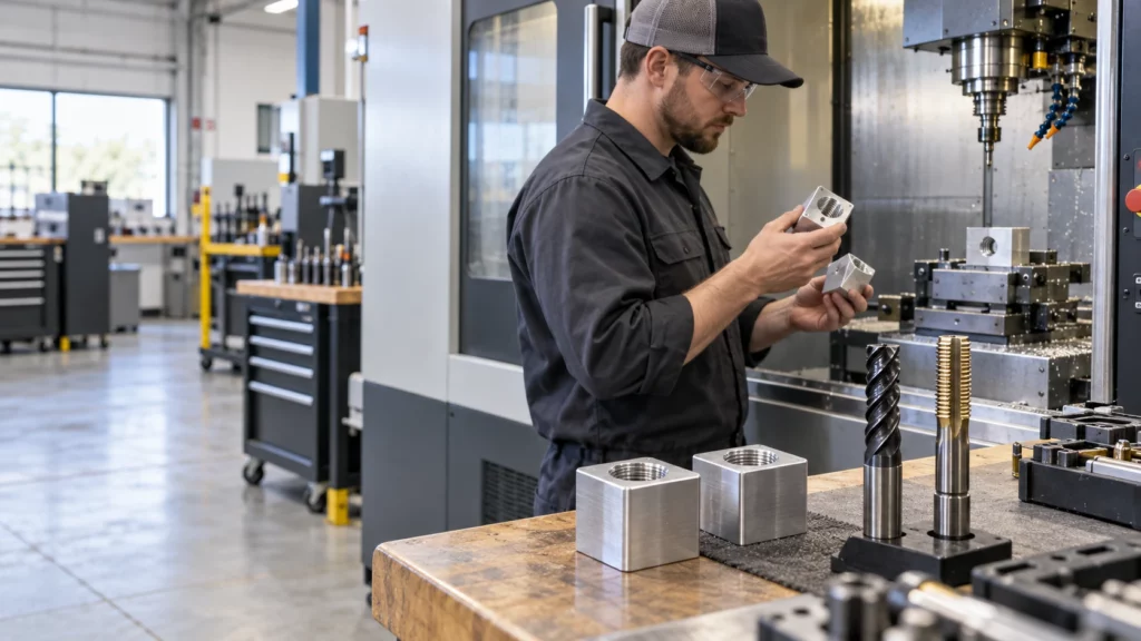
A machinist inspects two aluminum blocks with internal threads beside a tap and a thread mill in a CNC workshop.

The choice between tapping and thread milling depends on the hole, material, thread specification, production quantity, machine capability, and cost of failure. Tapping is usually the faster route for repeat production of standard internal threads. Thread milling offers more control over thread size and fit, handles a wider range of diameters with fewer tools, and can reduce the consequence of a tool failure in a valuable part.

Neither process is universally better. A through-hole in a stable aluminum part may favor tapping, while a large thread, difficult material, expensive near-finished component, or close fit adjustment may justify thread milling. Blind-hole geometry and usable thread depth can change the answer again.

Tapping vs Thread Milling at a Glance

Decision factor Tapping Thread milling
Cycle time Often faster for standard repeated threads. Usually longer because the tool follows a helical path.
Tool flexibility One tap normally matches a specific size, pitch, and form. One cutter may cover multiple diameters that share a compatible pitch and profile.
Fit adjustment Limited after the tap and hole preparation are selected. Tool-path offsets can adjust the finished thread within process limits.
Failure risk A broken tap may be difficult to remove from the part. A smaller cutter may be easier to recover from, but breakage can still damage the feature.
Machine need Requires controlled feed and rotation appropriate to the tapping method. Requires CNC helical interpolation, suitable control, rigidity, and access.

How Each Process Cuts an Internal Thread

Both methods begin with a prepared hole, but their tool engagement is different. The drawing must specify the finished thread; the process planner then selects the pre-hole, tool, cutting data, and inspection route.
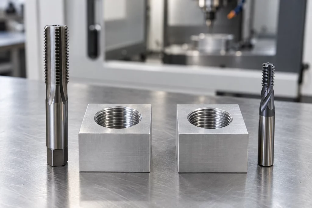
A large tap and a thread mill stand beside two aluminum blocks with machined internal threads.

Tapping

A tap advances axially while its cutting edges or forming lobes create the complete thread profile. Because the tool engages around the circumference, torque, alignment, lubrication, chip control, and the prepared-hole diameter are important. Cut taps generate chips. Form taps displace suitable ductile material without chips, but they require a different hole size and should be approved for the material and specification.

Thread Milling

A thread mill rotates while the CNC moves it along a helical path. The cutter is smaller than the finished thread, so it engages a portion of the circumference at a time. The program controls diameter and direction, and suitable cutters can produce internal or external threads. The method needs enough bore access, tool clearance, machine interpolation, and stable workholding.

Choose by Hole Geometry

Through Holes

Through holes usually provide easier chip evacuation and fewer bottom-clearance constraints. For standard sizes and meaningful batch quantities, tapping often provides the most efficient cycle. A spiral-point cutting tap may push chips ahead through the opening when the material and application permit. Thread milling remains useful for large diameters, adjustable fits, mixed thread sizes, or parts where tool-breakage recovery influences the risk calculation.

Blind Holes

Blind holes need separate values for drilled depth, full thread depth, usable engagement, and bottom clearance. A tap has an incomplete lead before it produces full threads, and chips must have somewhere to go. Tap style, coolant delivery, chip evacuation, and reversal therefore matter. Thread milling can approach a shoulder with controlled axial positioning, but it still needs entry and exit clearance and cannot create usable thread beyond its programmed geometry. Do not specify “thread to bottom” without defining a manufacturable termination.

Choose by Material and Thread Specification

Material behavior affects torque, chips, tool wear, heat, and edge quality. Standard threads in machinable aluminum may favor tapping for speed, although chip packing or built-up edge still needs control. Tough stainless steels, high-temperature alloys, or expensive heat-treated parts may make the lower engagement and recovery advantages of thread milling more attractive. The supplier should confirm the exact alloy, hardness, and hole depth before choosing the route.

Thread size and form matter as much as material. Small standard threads may suit tapping, while larger diameters, special profiles, right- and left-hand variants, or adjustable fit classes can favor thread milling. A thread mill is not universal: its diameter, pitch capability, length, cutting form, and reach must match the feature.

Choose by Quantity and Cost of Failure

For a stable high-volume job, the shorter cycle of tapping can outweigh its lower flexibility. For prototypes and mixed families, thread milling may reduce the number of dedicated tools and allow diameter correction through offsets. The value of the workpiece also matters. Breaking a tap in an almost-complete housing can cost more than the saved cycle time; however, thread milling adds programming time and may use a more expensive cutter. Compare total route cost, not tool price alone.

Define the Thread Correctly on the Drawing

A process comparison cannot correct an incomplete specification. Use the same feature-based discipline applied to CNC machining tolerances, and include the following information:

  • Thread standard and designation, nominal size, pitch or threads per inch, internal class or tolerance, and right- or left-hand direction.
  • Through or blind condition, drilled depth, full thread depth, minimum usable engagement, entrance chamfer, and any bottom-clearance limit.
  • Material grade and condition, heat treatment, coating or plating, quantity, critical datum relationships, and mating-fastener information.
  • Inspection method, gauge standard, sampling level, first-article record, and any functional assembly test.

A complete CNC machining RFQ checklist also keeps model, drawing, revision, finish, and inspection assumptions consistent across bidders.

Verify the Sample and Production Route

Inspect the pre-hole as well as the finished thread. Confirm location, diameter, depth, chamfer, burr condition, and cleanliness. Use the specified GO and NO-GO gauges or another agreed method, then test the real mating fastener when assembly behavior matters. Record tool offsets and wear limits for thread milling, or torque, tap life, and chip-control checks for tapping. A first article should also confirm that coating, plating, or heat treatment does not invalidate the final fit.

Evaluate Supplier Capability Against the Part

CK Metal Tech publishes precision machining capabilities that include CNC milling, drilling, tapping, and related inspection resources. Its broader CNC machining services for precision metal parts provide the context for OEM process planning. The project review should still confirm whether tapping, thread milling, or another threading method is available and appropriate for the specific size, material, depth, tolerance, quantity, and inspection plan.

Заключение

Use tapping when a standard internal thread, suitable material, controlled hole, and repeat quantity make cycle time the priority. Consider thread milling when fit adjustment, large or varied sizes, difficult materials, blind-hole constraints, or the cost of a trapped broken tap changes the economics. The drawing and sample plan should make the choice verifiable rather than leaving it to habit.

Часто задаваемые вопросы

Is Thread Milling Always More Accurate Than Tapping

No. Either process can make acceptable threads when the machine, tool, hole preparation, setup, and inspection suit the requirement. Thread milling offers useful diameter adjustment, but it does not replace process control.

Which Process Is Better for Blind Holes

It depends on usable depth, bottom clearance, material, chip control, thread size, and quantity. A suitable tap can be efficient; thread milling can improve control where evacuation or failure consequences are difficult.

Can One Thread Mill Cut Several Thread Sizes

Sometimes. A cutter may cover multiple diameters with a compatible pitch and profile, within its diameter and reach limits. Confirm the tool manufacturer’s range and the required thread form.

How Should an Internal Thread Be Inspected

Use the drawing’s specified gauge or measurement method and sampling plan. GO and NO-GO gauges are common, but depth, location, surface condition, and functional assembly may also require verification.

23rd Октябрь 2026
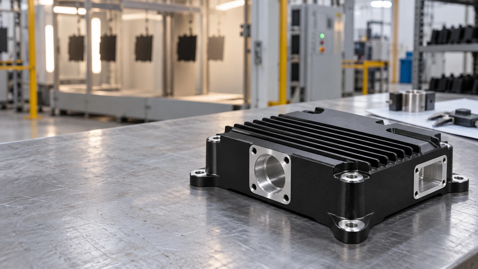
Can CNC-Machined Aluminum Housings Be Powder Coated? Thermal Interfaces, Fits, and Masking

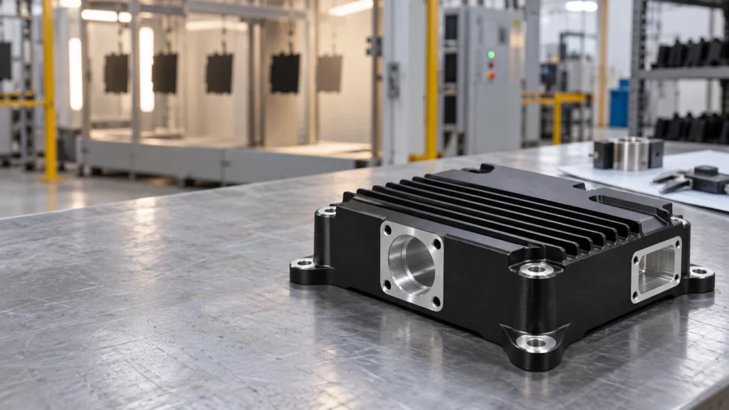
A black finned aluminum housing with silver machined bores and mounting faces rests on a workbench in a manufacturing shop.

Can aluminum be powder coated after CNC machining? Yes, provided the drawing distinguishes cosmetic or protective surfaces from interfaces that must remain dimensionally, electrically, or thermally functional. A coating that performs well on an exterior wall can cause interference in a close fit, obstruct a thread, insulate a bonding point, or add thermal resistance at a heat-transfer joint.

The review should therefore start with the finished assembly, not the color. CK Metal Tech’s aluminum alloy cooling and shielding cover plate illustrates why this distinction matters: one machined component may combine an exterior cover, mounting holes, grooves, structural bosses, shielding functions, and heat-dissipation duties. Those surfaces should not automatically receive the same finish treatment.

Map Functional Surfaces Before Coating

Create a finish map on the controlled drawing or model. Identify coated faces, cosmetic faces, no-coat zones, and surfaces whose final dimensions apply after finishing. A generic note such as “powder coat black” does not tell the manufacturer how the housing must assemble or perform.

Surfaces Commonly Suitable for Coating

Exterior walls, non-mating covers, guards, and handling surfaces are typical candidates when the selected pretreatment and powder system match the aluminum alloy and service environment. Coating can support appearance and surface protection, but corrosion, chemical exposure, ultraviolet exposure, and cleaning requirements still need project-specific confirmation.

Surfaces That Often Need Masking

Common no-coat candidates include bearing or bushing seats, locating datums, close-tolerance bores, sliding rails, O-ring lands, sealing faces, connector grounds, threaded holes, fastener seats, and direct thermal contact pads. The decision is functional rather than categorical: a clearance hole may tolerate film build, while a locating hole with the same nominal diameter may not.

Mask Boundaries Need Their Own Definition

A no-coat note should show where the boundary begins, which direction the mask may shift, and whether a small transition band is acceptable. This is important around countersinks, spotfaces, grooves, stepped bores, gasket lands, and thermal pads. Masking has practical placement variation, and the cured edge may not form a perfectly sharp geometric line. Keep the boundary away from a sealing path or precision datum where possible. If the transition itself affects function, dimension it from a stable feature and include it in the first-article inspection plan.

How Powder Coat Changes Functional Interfaces

Powder coating adds material to the surfaces it covers. The actual build depends on the powder, application, grounding, part geometry, racking, and cure route, so the drawing should define the finished requirement instead of assuming a universal allowance.

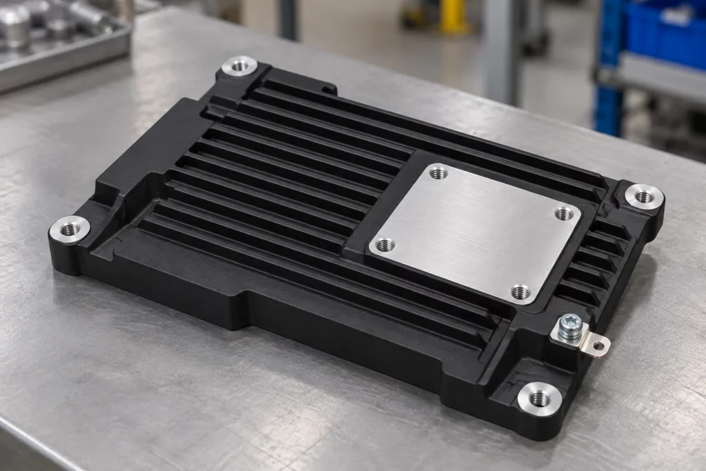
A black powder-coated aluminum housing has an exposed silver rectangular thermal contact surface and uncoated mounting holes.

Feature Coating risk Drawing or process control
Fits and threads Film build reduces clearance and can obstruct engagement. Mask, allow for the finish, or approve controlled post-coat machining.
Grounding points The organic film can interrupt metal-to-metal electrical contact. Mark bonding pads and define continuity or resistance verification.
Thermal interfaces The coating and any trapped air can add resistance at a contact joint. Keep direct-contact pads bare when required and define flatness, pressure, and interface material.
Sealing and datums Build-up or an uneven mask edge can change seating and measurement references. State whether dimensions apply before or after coating and locate mask boundaries.

Fits and Threaded Features

Check each fit against its mating component and the finished-state tolerance. The same feature-level reasoning used for CNC machining tolerances applies after coating. Thread masks must protect the required diameter, lead-in, and usable depth. Forcing a screw through cured powder is not a controlled acceptance method because it can damage the finish and leave debris in the assembly.

Grounding and Thermal Contact

A designated grounding pad needs a clean boundary, a suitable fastener interface, and a defined verification method. Bare aluminum may also need a compatible protection strategy that preserves conductivity. For heat-transfer pads, evaluate coating together with contact area, surface flatness, clamping pressure, and any thermal interface material. A sample should be tested under representative heat load when temperature performance is critical.

Coordinate CNC Machining and Powder Coating as One Route

The safest sequence is established before chips are cut. Treat masking, finishing, and final inspection as part of the manufacturing plan rather than instructions added after machining.

  1. Review the current drawing, aluminum grade or approved alternative, functional interfaces, cosmetic zones, and operating environment.
  2. Machine the housing with any agreed allowance for surfaces controlled in the finished state; deburr edges without altering critical geometry.
  3. Clean and pretreat the part using a route compatible with the alloy, contamination condition, and specified coating system.
  4. Install plugs, caps, or high-temperature masking at the defined boundaries, then verify mask seating before spraying.
  5. Apply and cure the coating, remove masks cleanly, and inspect boundaries for lifting, chips, or unintended coverage.
  6. Complete only approved secondary machining or thread restoration, then clean the part and protect newly exposed aluminum as required.

An integrated review can connect the company’s precision machining capabilities with its powder coating service. The exact masking materials, post-coat operations, and inspection methods should still be confirmed for the part.

Verify the First Article Before Production

A first article should prove more than color and appearance. Use the actual mating components or representative gauges where possible, and record the drawing revision and coating specification used for approval.

  • Dimensions: measure critical fits, datums, hole locations, and flatness in the state specified on the drawing.
  • Assembly: install fasteners, covers, seals, rails, connectors, and locating features without forcing or finish damage.
  • Electrical function: verify required bonding or shielding continuity at the specified contact points.
  • Thermal function: check temperature performance under a representative load when the housing forms part of the heat path.
  • Finish: inspect coverage, cure evidence, mask edges, handling damage, and cosmetic acceptance against an agreed reference.

Record nonconforming features separately. A part should not pass because its exterior looks uniform when a thread, bonding pad, thermal interface, or locating surface fails its own requirement.

What to Put in the Drawing and RFQ

Submit the 2D drawing and 3D model with material, quantity, coating system or performance requirement, color and texture, finished-state dimensions, no-coat zones, mask depth, thread callouts, grounding locations, thermal pads, inspection records, mating-part information, and sample approval criteria. Separate prototype quantity from expected production volume so the supplier can evaluate masking fixtures and process controls appropriately.

Заключение

CNC-machined aluminum housings can be powder coated successfully when the finish map protects the part’s working interfaces. The design should preserve required clearance, thread engagement, electrical bonding, and thermal contact, while the process plan should connect machining, pretreatment, masking, coating, and finished-state inspection.

Часто задаваемые вопросы

Should Every Threaded Hole Be Masked

No. Masking depends on thread function, fastener fit, engagement depth, and the approved finishing route. The drawing should identify which threads must remain coating-free and how they will be checked.

Can Powder Coat Be Allowed for in a Close Fit

Sometimes, but the designer and manufacturer must agree on the final clearance and whether the controlling dimension applies before or after coating. Do not rely on a generic film allowance.

Should a Thermal Contact Pad Remain Bare

Often it should when direct metal contact is part of the heat path. Confirm the complete joint, including flatness, contact pressure, interface material, corrosion protection, and the required thermal test.

Is Post Coating Machining Acceptable

It may be, if the operation is planned. Control chips, protect the surrounding finish, re-inspect dimensions, and define how newly exposed aluminum will be handled.

Request a Joint Machining and Coating Review

Send CK Metal Tech the drawing revision, alloy, quantity, mating-part details, coating requirements, no-coat zones, thermal duty, grounding needs, and inspection expectations. Use the request a joint machining and coating review route to confirm the manufacturing sequence before quotation.

22nd Октябрь 2026

One Metal Supplier vs Multiple Vendors: How to Calculate Total Landed Cost

A wide view of an industrial metal fabrication workshop with sheet metal machinery and an operator working at a production station.

One metal supplier can reduce transfers between fabrication, finishing, and assembly, but supplier consolidation does not automatically lower total landed cost. Compare both routes at the same delivery destination, then add the buyer-side costs needed to turn delivered parts into accepted assemblies. Keep those layers separate: shipping and import charges belong in the landed-cost calculation; supplier administration, inventory, and integration costs belong in the broader sourcing decision.

For an OEM buying custom metal parts, this distinction prevents a lower piece price from hiding extra work. It also avoids calling every future operating expense a landed cost.

Define the Deliverable Before Comparing Vendors

Start with one controlled bill of materials and drawing revision. Specify material, finish, quantity, inspection criteria, packaging, destination, and assembly responsibility. A coated panel from one vendor cannot be compared directly with an assembled enclosure from another unless the missing operations are priced separately.

Distinguish process splitting from dual sourcing. Sending cutting to one shop and coating to another creates sequential handoffs. Qualifying two independent suppliers for the same finished assembly creates a backup route. These arrangements have different costs and continuity benefits; combining them under “multiple vendors” obscures the decision.

Calculate Total Landed Cost in Two Layers

The core shipment calculation is:

Landed cost = supplier invoices + separately charged tooling + packaging + freight + insurance + applicable duties, taxes, and clearance fees.

The International Trade Administration’s landed-cost guidance supports the product-plus-delivery approach. For metal parts, verify which charges are already included in each quotation. Add only costs outside the quoted scope, and use the same receiving location.

Then calculate a separate management metric:

Sourcing comparison cost = landed cost + buyer assembly and inspection + supplier administration + inventory carrying cost + evidence-based quality and disruption allowances.

This second formula is a purchasing decision tool, not a customs valuation or accounting rule. It does not include equipment operating costs over the product’s lifetime. Keep recoverable taxes and other accounting treatments identifiable for finance review rather than treating every cash payment as a permanent expense.

Normalize Quotes and Allocate Shared Charges

Use the same currency, demand period, release size, and named delivery point. Record the delivery term and which party pays each freight leg. A quote that includes shipping can appear expensive beside a factory-gate quote until the missing freight is added.

For international purchases, ask a qualified broker to verify classification, origin, applicable charges, and the relevant shipment date. Do not copy a tariff percentage from another part or last year’s order.

Allocate shared freight across a mixed shipment using a defensible driver, such as chargeable weight or occupied volume. Allocate tooling over the realistically committed program quantity, with tooling ownership shown separately. Show first-order and repeat-order costs independently; an optimistic lifetime volume can conceal a costly launch.

A Worked Example for One Thousand Assemblies

The following figures are hypothetical USD amounts, not CK Metal Tech quotations or tariff estimates. Both routes ultimately provide 1,000 accepted assemblies. The single supplier includes assembly in its invoice; the split route requires more buyer assembly work. Charges already included in supplier invoices are excluded from the other rows.

Cost category One supplier Multiple vendors
Supplier invoices $40,000 $37,000
Tooling and setup $3,000 $2,200
Packaging freight and insurance $1,800 $3,300
Illustrative import and clearance charges $1,500 $1,500
Core landed cost $46,300 $44,000
Buyer assembly and inspection $800 $3,300
Supplier administration $400 $1,200
Inventory carrying cost $600 $1,100
Expected quality and rework allowance $600 $1,800
Sourcing comparison total $48,700 $51,400
Cost per accepted assembly $48.70 $51.40

Multiple vendors win the core landed-cost comparison by $2,300. After buyer-side costs are included, one supplier is lower by $2,700. This result follows the stated assumptions; it does not prove that consolidation is generally cheaper.

The decision changes if the split route reduces internal assembly effort, avoids quality losses, or provides a valuable qualified backup. Replace every allowance with program evidence before using this example for an award decision.

Measure Handoffs Without Double Counting

Map the route from cutting and forming through machining, coating, final inspection, and packing. Sheet metal fabrication may involve several linked operations, so track the transfers between them rather than counting suppliers alone.

For each handoff, record transport, protective packaging, receiving inspection, queue time, and revision-control responsibility. Estimate internal work from hours multiplied by an approved labor rate. Distinguish cash savings from staff capacity released: fewer purchase orders do not necessarily reduce payroll.

Estimate inventory carrying cost from average inventory value, the approved annual carrying rate, and the time period. Use historical rework and expedite costs where available. For a new program, show low, expected, and high cases rather than inventing a precise failure probability.

Avoid charging the same loss twice. If rejected units already reduce the accepted-unit denominator, check whether a separate scrap allowance repeats that loss. Likewise, do not add replacement freight when it is already included in a rework estimate.

Choose the Route and Test Its Weak Points

One supplier is attractive when interfaces dominate the program: welded frames must match machined brackets, coating boundaries affect fit, and completed assemblies require a coordinated release. Multiple vendors may be preferable when a process needs specialist qualification, capacity is constrained, or a genuinely independent backup is essential.

A backup is only useful if drawings, tooling access, qualification status, and available capacity make it executable. Two suppliers sharing the same critical subcontractor may still have a common interruption risk. Keep continuity requirements visible beside the cost comparison.

Test the decision against smaller releases, a rejected batch, an engineering change, and an expedited shipment. If the winner changes under a small assumption adjustment, resolve that uncertainty before committing the production route.

Request a Comparable Metal Manufacturing Quote

CK Metal Tech combines sheet metal processing, machining, stamping, powder coating, painting, and precision-component assembly. Review its metal manufacturing and assembly capabilities against the proposed route; process breadth alone does not establish capacity or suitability for a particular program.

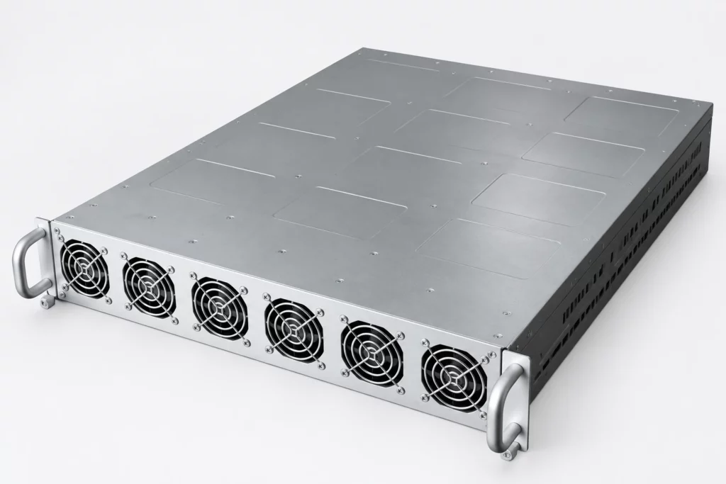
A silver rectangular metal enclosure with a row of cooling fans, ventilation slots, and side handles is shown against a plain background.

Send the BOM, controlled drawings, quantities, destination, finish requirements, and acceptance plan. Ask CK Metal Tech to separate tooling from recurring prices and identify subcontracted operations, excluded services, and packing assumptions. Give alternative vendors the same package.

Заключение

Choose the sourcing route using both delivered cost and the work required to obtain accepted assemblies. A transparent comparison can show that multiple vendors win on landed cost while one supplier wins after integration costs, or the reverse. Award the route whose cost assumptions and continuity requirements can be verified.

Часто задаваемые вопросы

Is one metal supplier always cheaper

No. Consolidation may reduce transfers and administration, while multiple vendors can provide specialist capability or backup capacity. Compare equivalent outputs and documented costs.

Is total landed cost the same as total cost of ownership

No. Landed cost addresses acquisition and delivery. Ownership cost extends into use, maintenance, and disposal. Buyer integration costs should remain a clearly labeled comparison layer.

How should tooling be included

Show the initial tooling payment separately, then allocate it across a defensible committed quantity for the unit comparison. Record ownership, maintenance responsibility, and repeat-order assumptions.

Should supplier management time count as a saving

Include it when comparing resource demand, but distinguish released staff capacity from actual cash savings. Use measured hours and an approved rate.

Request a Sourcing Route Review

Share the current drawings, BOM, delivery location, release schedule, and assembly scope with CK Metal Tech. Request a sourcing-route review to clarify included operations and compare the assumptions behind each quotation.

16th Октябрь 2026

How to Prevent Edge Rust and Thread Build-Up on Powder-Coated Sheet Metal Parts

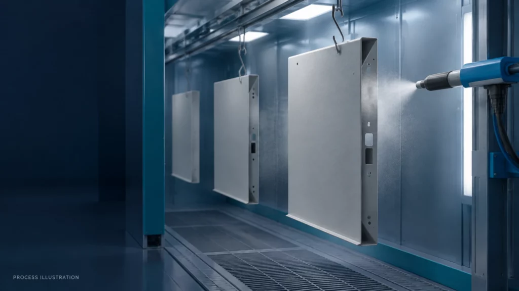
Sheet metal panels hang from an overhead conveyor as a spray gun applies powder coating inside an industrial finishing booth.

Powder coating inspection should verify exposed edges and functional threads before an OEM approves a sheet metal part for production. A uniform-looking panel does not establish edge protection, and an acceptable uncoated thread may become unusable after finishing. Preventing edge rust and thread build-up therefore requires a feature-level control plan, with checks before coating, after curing, and after handling.

This guide focuses on first-article acceptance and repeat-production controls. For the broader defect mechanisms, the edge rust and thread build-up guide provides background. The task here is to convert those risks into documented release criteria.

Define the Features That Must Pass

Mark critical edges, internal threads, threaded studs, grounding contacts, and mating surfaces on one drawing revision. Assign each feature an identifier so the inspection record refers to a physical location rather than “check edges” or “mask threads.”

State the substrate, operating environment, coating system, finish requirements, and surfaces that must remain coating-free. Edge rust specifically concerns susceptible ferrous substrates; aluminum does not develop iron rust, although its corrosion protection still needs evaluation.

Separate appearance acceptance from functional acceptance. Agree the viewing conditions and reference sample for cosmetic faces. Specify thread-gauge or assembly requirements independently, and identify which corrosion tests are needed for qualification rather than routine lot release.

Check Edge Preparation Before Coating

Inspect the actual fabricated sample before it enters pretreatment. Record burr removal, sharp transitions, cut residue, weld contamination, and surfaces that retain moisture or debris. Photograph the identified critical edges at a usable scale.

Set the edge condition through the design and finishing review. There is no universal edge radius suitable for every thin sheet, hole, or flange. Specify a feasible condition that protects the required interface without changing dimensions or damaging a mating feature.

Coordinate these requirements with the sheet metal fabrication process. Cleaning cannot substitute for removing an unacceptable burr, and a cosmetic coating should not be expected to hide an unstable substrate condition.

Record the approved pretreatment route and the coating product reference. Any primer or enhanced corrosion system should be selected against the exposure requirement and confirmed as compatible; do not prescribe one system for every enclosure.

Verify the Thread Masking Boundary

For each coating-free thread, define the masked depth or length and the surrounding boundary. A through-hole, blind tapped hole, and external stud require different access and protection. The instruction should establish what remains bare, including any functional lead-in or adjacent contact surface.

Ask the finishing team to document the selected plugs, caps, or other masks and their compatibility with the process temperature and chemistry. Check their fit on the first article before spraying. Reusable masks need a defined cleaning and replacement condition; worn or poorly seated masks can change the result.

Plan hardware installation and secondary machining in the same route. If an insert is installed before coating, confirm its masking requirements. If threads are cut or chased afterward, approve the operation and the corrosion protection of any newly exposed metal. Bare threads and grounding areas may require a separate protection strategy that preserves their function.

Do not treat forcing a screw into a coated thread as an acceptance method. It can conceal interference and damage the finish around the entrance.

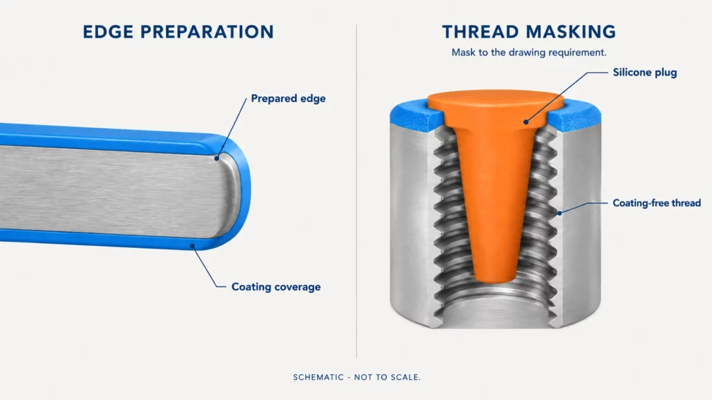
Technical diagram compares a prepared, coated sheet-metal edge with a threaded hole protected by a silicone plug, showing the coating coverage and coating-free thread.

Measure Coating Without Missing the Edge

Use the applicable dry-film thickness measurement practice and the project’s approved limits. Verify the instrument on the relevant substrate and define measurement locations and sampling frequency. A single convenient reading on a flat face does not represent the whole part.

Check critical edges for coating continuity, exposed substrate, chips, and damage at the masking boundary. Thickness probes can have geometry and proximity limitations; do not assign an unreliable edge reading the same status as a valid flat-surface measurement. Where edge performance is critical, agree an appropriate qualified measurement or test method with the responsible coating engineer or laboratory.

For thermoset powder coatings, request evidence that the actual part temperature and time meet the coating’s curing instructions. An oven setting alone is insufficient evidence, especially when load configuration changes. Keep cure verification distinct from thickness and visual inspection.

Build a Powder Coating Inspection Record

Use a compact record linking every check to its requirement. The following structure is a starting template, not a universal specification or sampling plan.

Checkpoint Required evidence Release basis
Edge before coating Feature photograph and preparation record Approved edge condition met
Mask before spraying Boundary and depth confirmation Drawing no-coat area protected
Edge after curing Local coverage and damage inspection Defined edge criteria met
Thread after mask removal Specified gauge result and fit check Thread and assembly requirements met
Coating condition Thickness and cure records Approved coating limits met
Part after handling Packing trial and contact-area check No unacceptable finish damage

Keep the actual result, inspector, sample identity, drawing revision, and disposition with each checkpoint. Record deviations explicitly; an attractive reference sample should not silently override a failed functional feature.

A mating-fastener check is useful, but it does not replace a thread gauge when the specification requires gauging. Likewise, a broad appearance approval does not close an unresolved edge-protection requirement.

Qualify Corrosion Protection Separately

When corrosion validation is required, define the test method, specimens, exposure period, relevant edges, and evaluation criteria before testing. Representative specimens should reproduce the agreed substrate, preparation, coating system, and critical geometry. A flat coupon may verify the coating system without demonstrating the behavior of the actual cut edge.

Он salt-spray test practice provides controlled exposure conditions; it does not set one product-wide duration or convert test hours into outdoor service years. Establish qualification against the customer requirement rather than using an impressive hour count as the entire acceptance claim.

Review adhesion, cure, and corrosion evidence as separate checks. Agree whether testing uses sacrificial production parts or representative specimens, and keep destructive tests out of saleable units unless explicitly approved.

Transfer First Article Findings to Production

Convert the approved sample route into a production control plan. Assign responsibility for edge preparation, mask installation, coating verification, final thread checks, and packing. Set sampling or complete inspection according to feature criticality and the customer’s requirements; neither approach is automatically correct for every part.

Define requalification triggers, including changes to edge geometry, substrate, pretreatment, coating product, masking, racking, curing load, or hardware sequence. Retain traceability so a failed feature can be linked to the affected production lot.

CK Metal Tech provides fabrication alongside powder coating and painting services. For a combined route, ask its technical team to confirm the proposed controls, available inspection methods, and any external laboratory work before quotation. Do not infer a specific testing capability from the availability of a coating line.

Заключение

Preventing edge rust and thread build-up requires an acceptance plan that follows the feature through fabrication, coating, and handling. Approve the preparation and masking route, verify the finished interfaces, and transfer those checks into production. Appearance, thread fit, and corrosion qualification should remain distinct release decisions.

Часто задаваемые вопросы

Does a passing thickness reading prove edge protection

No. It establishes thickness at the measured location. Critical edge coverage and the specified corrosion requirement need their own verification.

Should every threaded hole be masked

Review each feature against its functional requirement. Masking is appropriate where coating would interfere, but the drawing must define the boundary and any bare-metal protection.

Can coated threads be chased after curing

Only through an approved secondary operation. Review thread dimensions, finish damage, debris removal, and protection of exposed substrate before accepting the route.

Should every production part undergo corrosion testing

Not necessarily. Define qualification testing and routine lot controls separately, using the customer specification and the risk of the application.

Request a Coating Control Plan Review

Send CK Metal Tech the current drawings, substrate, coating specification, operating environment, masking requirements, and photographs of affected features. Request a coating control-plan review to establish first-article checks and confirm the production scope.

15th Октябрь 2026

How Security Inspection Equipment Chassis Are Made: Sheet Metal Fabrication, Powder Coating and Assembly

How Security Inspection Equipment Chassis Are Made Sheet Metal Fabrication, Powder Coating and Assembly

A security inspection equipment chassis has to do more than enclose electronics. It must preserve alignment, protect modules, allow service access, and present a controlled exterior in demanding public environments. The practical route is integrated: design the sheet metal structure around the equipment, apply a suitable finish, then complete and verify the assembly as one system. This guide covers the key decisions buyers should clarify before quoting. For a product-level reference, review CK Metal Tech’s сборка шасси оборудования для проверки безопасности.

A well-designed sheet metal equipment enclosure coordinates rails, doors, cable routes, ventilation, grounding, and mounting points before material is cut. Treating fabrication, coating, and assembly as separate purchases can create fit-up gaps or late rework. Good engineering-to-production handoff is central to predictable equipment chassis assembly.

Why Security Inspection Chassis Design Requires More Than a Metal Shell

Security inspection equipment often operates where public access, continuous duty, and technician access overlap. The chassis must support the equipment without obstructing its working envelope, while remaining practical to clean, service, move, and integrate with adjacent structures. A panel that looks acceptable in a drawing can still block a cable bend, restrict a door swing, or make a high-use component difficult to replace.

Before fabrication, confirm the structural loads, access panels, heat and cable-routing needs, and surfaces requiring corrosion or abrasion resistance. Those answers help determine whether to use SPCC cold-rolled steel, SUS304 stainless steel, aluminum profiles, or a combination. Material selection should follow the equipment and environment.

From Flat Sheet to Serviceable Chassis: The Manufacturing Flow

A controlled workflow normally starts with drawing and interface review, followed by CNC laser cutting, CNC bending, welding or riveting, surface preparation, electrostatic powder coating, component installation, and system debugging. Each step must protect the dimensions and interfaces established previously so the finished enclosure remains serviceable after coating and assembly.

Sheet metal security inspection equipment chassis ready for assembly

Sheet Metal Fabrication Sets the Geometry

The fabrication stage converts the equipment envelope into panels, brackets, doors, bases, rails, and other structural parts. A precision sheet metal fabrication review should confirm bend allowances, hole locations, tolerance stack-up, weld access, hardware clearances, and the sequence used to maintain squareness. CNC laser cutting supports repeatable openings and mounting patterns, while CNC bending establishes stiffness and alignment. Welding or riveting is selected according to load, access, finish, and service requirements. CK Metal Tech’s precision sheet metal fabrication capability can be evaluated against the project’s drawings and interface needs.

Small details can determine whether the final security inspection chassis is easy to use: front maintenance doors, removable covers, guide rails, grounding points, cable entries, and lock clearances. The drawing review should also identify surfaces that must remain uncoated, threaded holes needing protection, and areas where welded distortion could affect fit.

Powder Coating Creates the Protective Outer Layer

Powder coating is more than a color choice. Pretreatment, masking, grounding, edge coverage, curing, and film build all influence how the finished chassis performs and assembles. A powder coated chassis can provide a clean, durable exterior for many indoor equipment applications, but it is not automatically suitable for every chemical, humidity, outdoor, or cleaning environment. The coating system should be matched to the substrate and exposure, and any appearance or corrosion target should be confirmed in the project specification. CK Metal Tech’s powder coating service can be considered as part of that finish review.

Before coating, identify threaded interfaces, contact points, sliding surfaces, labels, and grounding locations that require masking or post-process inspection. After coating, doors and rails should be checked for build-up that could affect movement. Color consistency matters in public-facing equipment, but functional checks matter just as much: an attractive finish cannot compensate for blocked threads, poor bonding, or a panel that no longer seats correctly.

Equipment Chassis Assembly Closes the Loop

Assembly is where the fabricated structure is tested against real service conditions. Depending on the agreed scope, it may include stainless-steel rails, locks, panels, brackets, fasteners, and equipment modules, followed by fit checks and system debugging. The assembly team should verify door swing, rail travel, fastener access, cable paths, grounding continuity, and the relationship between removable parts and maintenance tasks. This is also the stage to catch coating damage, interference, missing hardware, or tolerance issues before packaging.

A supplier that handles fabrication, finishing, and assembly together can reduce handoff risk, but the scope still needs to be written clearly. Specify whether the deliverable is a bare enclosure, a powder-coated structure, a partially equipped chassis, or a tested assembly. Clear scope prevents a technically correct part from becoming an incomplete project deliverable.

What to Confirm Before Requesting a Quotation

A useful RFQ gives the manufacturer enough information to evaluate structure, finish, and assembly together. The following items turn a general request for a custom equipment chassis into a reviewable manufacturing package:

  1. Envelope and interfaces: provide overall dimensions, equipment clearances, door swing, mounting-hole patterns, cable-entry locations, and connections to conveyors, cabinets, or adjacent frames.
  2. Material and finish: state preferred materials, visible-surface expectations, coating color, gloss or texture requirements, uncoated areas, and exposure to moisture, cleaning agents, or abrasion.
  3. Load and operating conditions: identify static or moving loads, vibration, heat sources, humidity, indoor or outdoor use, service frequency, and any target sealing level that must be verified against the final design.
  4. Assembly scope: list rails, locks, panels, fasteners, modules, wiring interfaces, and debugging or fit-check activities that should be included, along with customer-supplied components.
  5. Quality and delivery information: include drawing revision, quantity, inspection expectations, packaging constraints, and acceptance points that determine whether the completed chassis is ready for installation.

Where This Approach Fits

The same fabrication-to-assembly logic supports several security environments, but priorities differ. Airports, stations, and subway facilities may emphasize clean public-facing surfaces, reliable access doors, and easy maintenance. Customs areas and logistics parks may emphasize impact resistance, equipment protection, cable management, and repeatable material-handling integration. Temporary screening may require compact transport and a finish that remains presentable after repeated handling.

Reflect these differences in the drawing package and acceptance criteria. A chassis designed for a controlled indoor room should not automatically be treated as an outdoor enclosure. A coating selected for appearance should not be assumed to provide a particular sealing or corrosion performance without confirming joints, doors, gaskets, fasteners, and penetrations.

Заключение

A dependable security inspection equipment chassis is the result of coordinated decisions, not a single fabrication operation. Sheet metal design establishes the structure and interfaces. Powder coating protects and presents the exterior when the coating system matches the environment. Equipment chassis assembly confirms that doors, rails, fasteners, modules, and service access work together. By defining materials, loads, clearances, finish requirements, assembly scope, and acceptance checks before production, buyers can reduce avoidable rework and compare suppliers on practical project fit rather than enclosure appearance alone.

Часто задаваемые вопросы

What materials are commonly used for a security inspection chassis?

Common options include SPCC cold-rolled steel, SUS304 stainless steel, and aluminum profiles. The choice depends on structure, corrosion exposure, weight, weldability, finish, and equipment interfaces.

Does powder coating replace sealing or environmental protection?

No. Powder coating protects coated surfaces, but overall environmental performance also depends on joints, doors, gaskets, fasteners, cable penetrations, and the enclosure design. Any target sealing level should be confirmed against the final specification.

What does equipment chassis assembly usually include?

It may include rails, locks, panels, brackets, fasteners, equipment modules, fit checks, and system debugging. Define the scope in the RFQ so the quotation matches the intended deliverable.

Can the chassis be designed for front maintenance?

Yes, front maintenance doors, removable panels, guide rails, and accessible fasteners can be incorporated when the equipment layout and service clearances are known. The design should be checked against real replacement and inspection tasks.

Request a Project-Specific Chassis Review

To evaluate a custom equipment chassis, share the equipment envelope, module layout, material preference, coating environment, expected load, drawing revision, quantity, and application conditions with CK Metal Tech. The technical team can then confirm feasible fabrication, finish, assembly scope, and specification gaps. Use the request application support route when you are ready to discuss the project.

8th Октябрь 2026

CNC Machining Tolerances: When Tight Tolerances Are Necessary – and When They Increase Cost


CNC Machining Tolerances When Tight Tolerances Are Necessary - and When They Increase Cost

When a drawing applies a very tight tolerance to every feature, the part can become more expensive without becoming more functional. CNC machining tolerances should be driven by fit, movement, sealing, alignment, and inspection needs – not by making every number look precise. A practical strategy gives critical features the right control and leaves non-critical dimensions at a manufacturable default. This guide explains when tight tolerances earn their cost and how to communicate them to a CNC supplier.

Ask what the feature does in the assembly. If it locates a bearing, controls a seal, or determines whether interchangeable parts fit, tighter control may be justified. If it is an external surface with clearance, a tighter number may only increase setup time, inspection, scrap risk, and quotation value.

What CNC Machining Tolerances Actually Control

A tolerance is the permitted variation around a nominal dimension. It is different from machine resolution or a general accuracy claim. The result depends on tooling, workholding, material, geometry, temperature, process sequence, and measurement method. Drawings may also control position, flatness, runout, surface finish, or thread fit; adding decimals cannot correct a poor datum scheme.

As a planning reference, some suppliers use +/-0.005 in (0.13 mm), while +/-0.001 in (0.025 mm) or tighter may require additional controls. These values are illustrative, not universal promises. Confirm capability against material, geometry, quantity, equipment, and inspection.

When Tight Tolerances Are Necessary

Tight tolerances are justified when variation can change function, assembly, safety, or service life. The need is usually feature-specific, not every feature.

Mating and Moving Features

Bearing seats, shafts, sliding guides, locating pins, press fits, and clearance fits depend on relationships between features. A shaft may need close control while a nearby shoulder does not. Specify the fit, material pair, temperature range, and motion instead of tightening the entire part.

Sealing and Pressure-Related Surfaces

O-ring grooves, sealing lands, mating flanges, valve seats, and fluid passages may need tighter size, form, surface-finish, or flatness control. Identify the sealing method, contact surface, finish, and leakage or pressure requirement rather than relying on a nominal diameter alone.

Alignment, Datums, and Interchangeability

Tight control can be valuable when a part locates a sensor, aligns a mechanical path, interfaces with a replaceable module, or accumulates with other parts. Position, perpendicularity, parallelism, and datum relationships may matter more than one linear dimension.

Inspection-Critical or Safety-Relevant Features

Dimensions tied to calibration, safety clearance, regulatory function, or a customer’s acceptance test deserve a defined measurement method and record. State whether inspection uses a CMM, gauges, vision, or functional testing so the tolerance is realistic and repeatable.

When Tight Tolerances Increase Cost Without Adding Value

A tight tolerance becomes expensive when it pushes a feature beyond the normal capability of the selected process. The added cost comes from the controls needed to hold and prove it.

More Setups and Slower Cutting

Very small limits may require extra passes, smaller tools, lower cutting loads, special workholding, or a second operation. Re-fixturing introduces another opportunity for datum shift, and the cost can exceed the value of the feature.

Material, Geometry, and Temperature Effects

Thin walls, deep pockets, long shafts, interrupted cuts, and uneven stock can deflect or distort. Aluminum, stainless steel, plastics, and heat-treated materials also respond differently to heat and clamping. A tolerance that is reasonable on a rigid block may be costly on a slender component.

Inspection, Rework, and Scrap

Tighter limits often require more in-process checks, calibration, final inspection, and documentation. Small variation can create rework or scrap even when the part would perform correctly. Cost also rises when the supplier inspects features the assembly never uses.

How to Match the Tolerance to the Feature

A better approach is to assign tolerances by function and then confirm that the manufacturing route can support them. Use the following decision rule during design review:

  1. If the feature mates or moves, define the fit or clearance and control the mating surfaces.
  2. If it locates another component, control position and datum relationships rather than every surrounding dimension.
  3. If it seals, define sealing geometry, finish, flatness, and inspection method.
  4. If it is cosmetic or non-functional, use a reasonable general tolerance and specify appearance separately.
  5. If no one can explain how it will be used or inspected, do not make the tolerance unnecessarily tight.

Holes and shafts are common sources of over-specification. A clearance hole does not need the same control as a locating hole. A threaded hole needs the correct thread standard, depth, and verification; an extremely tight minor diameter may not improve the connection. Call out flatness and parallelism when they control contact or alignment.

Keep surface finish and edge requirements separate from dimensional tolerance. A smoother finish may support sealing or sliding, while an edge break supports assembly and handling.

What to Put on the Drawing and RFQ

A supplier can price CNC machining more accurately when the drawing separates critical requirements from general ones. Include material, quantity, part size, critical features, datums, general tolerance standard, surface finish, threads, heat treatment, coating, and inspection records. State whether the requirement applies to a prototype, lot, or every interchangeable part.

For a practical document package, use a structured CNC machining RFQ checklist and mark the dimensions that affect fit, sealing, motion, or final acceptance. A supplier should be able to see which features require a capability review before quoting and which dimensions can follow the agreed general tolerance.

Define the measurement reference too: datum scheme, temperature when relevant, gauge or CMM method, sampling plan, and first-article reporting. This prevents the manufacturer and customer from evaluating the same feature in different ways.

How a CNC Supplier Should Verify Tight Features

Tolerance control is a process responsibility, not only a final inspection activity. A capable supplier reviews high-risk features, chooses a stable setup, monitors tool wear, and inspects critical dimensions. Micrometers and bore gauges may suit simple sizes, while a CMM or 2.5D system may suit positional relationships and profiles.

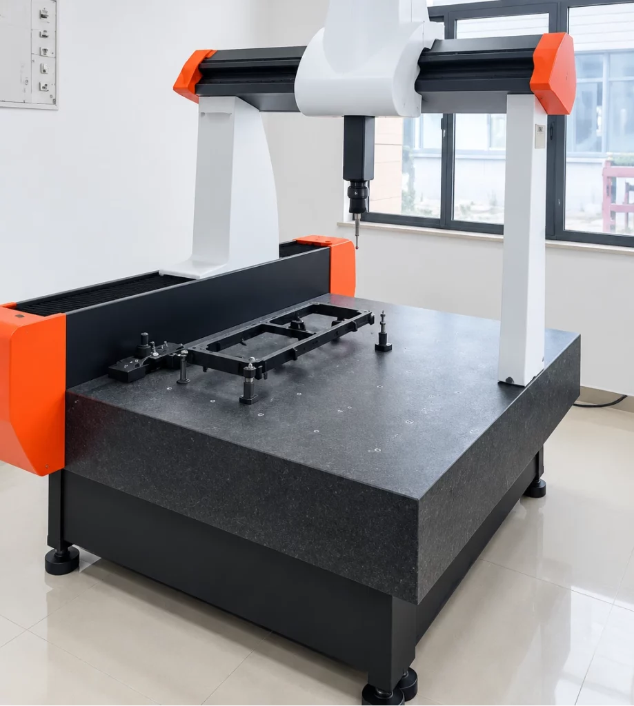
Coordinate measuring machine used for CNC part inspection

CK Metal Tech lists multi-axis CNC equipment, a 5-axis Swiss-type lathe, CNC lathes and milling machines, plus grinding, thread rolling, tapping, drilling, cleaning, polishing, and surface-preparation resources. Its laboratory resources include a 1200 x 1000 x 800 mm coordinate measuring machine, a 2.5D measurement system, and metallographic microscope and Vickers hardness equipment. Match those resources to the actual feature and inspection plan.

You can review the company’s precision machining capabilities and ask which process route and measurement method fit the drawing. Its quality management information can also help procurement teams understand the broader production and verification context.

Заключение

The best CNC machining tolerance strategy is selective. Tight tolerances are worth paying for when they protect a fit, seal, alignment relationship, safety function, or required inspection result. They add avoidable cost when applied to clearance features, cosmetic surfaces, or dimensions that do not affect assembly. By separating general tolerances from critical callouts, defining datums and inspection methods, and discussing process capability before release, engineering and procurement teams can improve part quality while keeping the quotation tied to real performance.

Часто задаваемые вопросы

What is a typical CNC machining tolerance?

There is no universal value. Many shops use around +/-0.005 in (0.13 mm) for general features, while tighter values require review of material, geometry, equipment, quantity, and inspection. Use the supplier’s confirmed capability.

Are tighter tolerances always better?

No. A tighter tolerance is better only when it protects a functional requirement. Otherwise it can increase setups, inspection, rework, and scrap without improving the part in service.

Which CNC features usually need tight tolerances?

Bearing seats, shafts, locating holes, sealing surfaces, precision threads, alignment datums, and interchangeable interfaces commonly need closer control. The value depends on the mating parts and operating conditions.

How can a buyer reduce CNC machining cost without lowering quality?

Identify critical features, relax non-functional dimensions, use clear datums, avoid unnecessary re-fixturing, and agree on inspection before production. A targeted scheme often delivers better value than a uniformly tight drawing.

Request a Tolerance and DFM Review

Share the part drawing, material, quantity, critical fit or sealing requirements, surface finish, tolerance callouts, and inspection expectations with CK Metal Tech. The engineering team can review whether the requested CNC machining tolerances match the feature function and recommend a process and measurement route. Use the request a tolerance review route for a project discussion.

1st Октябрь 2026
                           

Есть ли у вас какой-нибудь дизайн?
Поддерживать

контакт
Дом
WhatsApp
Электронная почта
Контакты