ЧУАНКАЙ

а я л а н д

Загрузка

     
дом // блог

блог

Sheet Metal Design for AI Server Racks and Data Center Cabinets: Strength, Airflow, Cooling Integration and RFQ Checklist


Sheet Metal Design for AI Server Racks and Data Center Cabinets Strength, Airflow, Cooling Integration and RFQ Checklist

AI server rack design must connect structural strength, airflow, cooling hardware, service access, and sheet metal manufacturability before drawings are released for quotation. A cabinet may fit every listed component yet still fail if rails deflect, exhaust air recirculates, cables block the rear path, or a late-added coolant manifold interferes with removable panels. The practical goal is to convert equipment loads and cooling architecture into a buildable data center cabinet design, a testable prototype, and an RFQ that different suppliers can quote on the same basis.

Define the Rack, Cabinet, and Cooling Scope Before Designing the Sheet Metal Structure

Distinguish AI Server Racks, Data Center Cabinets, and Aisle Containment

An open rack mainly supports equipment, rails, power distribution, and cables. A cabinet adds doors, side panels, top panels, access control, and a more controlled internal air path. Aisle containment is a room-level airflow system and should not be confused with the cabinet.

Buyers should identify responsibility for rails, filters, blanking panels, PDU brackets, cable accessories, grounding hardware, and final assembly. A rack fabricator may not cover containment panels, facility ducting, or coolant distribution equipment. Without a clear boundary, suppliers may quote different products under the same description.

Translate Air-Cooled, Liquid-Ready, and Hybrid Cooling into Mechanical Requirements

An air-cooled rack needs an unobstructed inlet and exhaust route. A liquid-ready design may also require manifold brackets, hose routing, quick-connect access, drip-management provisions, and service clearance. A hybrid rack must accommodate both liquid hardware and residual air-cooled loads.

ASHRAE recommends matching cooling architecture and airflow management to AI rack density and treating power and cooling as connected design decisions. Before freezing the sheet metal geometry, confirm the cooling method, component envelopes, service direction, and responsibility for thermal validation.

Design the Structure Around the Actual Load Path

Define Static Load, Center of Gravity, Anchoring, and Transport Conditions

Total equipment weight is only the starting point. Door-mounted hardware, PDUs, cables, manifolds, rear cooling assemblies, and extended service trays can change local loading and stability. State whether the cabinet will remain fixed, move on casters, be anchored, or ship with equipment installed.

The RFQ should identify installation orientation, lifting points, floor interfaces, service extension conditions, and transport expectations. A structure suitable for stationary use may not be suitable for loaded shipment. Missing these inputs prevents a defensible decision about reinforcement, base geometry, or connection design.

Select Material, Sheet Thickness, Stiffeners, and Joint Types

Increasing sheet thickness is not the only way to raise stiffness. Folded edges, return flanges, formed ribs, localized supports, closed sections, and shorter unsupported spans may control deflection with less added mass. The right route depends on cabinet size, openings, load location, production volume, and shipping method.

Structural Route Suitable Use Main Purchasing Checks
Welded frame Fixed installation requiring rigidity Distortion, datum control, finish access
Bolted frame Modular design or shipment in sections Joint security, alignment, repeat assembly
Hybrid structure Rigid load path with removable modules Tolerance stack-up and interface control

Any thickness or reinforcement proposal should be checked against the actual load case rather than copied from a standard enclosure.

Create a Controlled Airflow Path Through the Cabinet

Design the Front-to-Rear Air Path, Doors, and Leakage Control

For front-to-rear-cooled equipment, the intake area should align with server inlets and the rear zone should remain clear. Perforated doors must balance open area with stiffness, hinge loading, security, and filtration. A universal perforation percentage is unsuitable because pressure drop depends on pattern, occupied area, equipment fans, and system configuration.

Unused rack positions and panel gaps can create bypass airflow. Define blanking requirements, door seals, side clearances, and filter arrangements. Assess the prototype as an assembled cabinet with representative doors, rails, and components, not as isolated sheet metal parts.

Prevent Recirculation, Cable Blockage, and Top-of-Rack Hot Spots

Hot exhaust can return through open rack spaces, gaps around doors, top openings, or congested rear zones. Cable bundles, PDUs, crossmembers, and cooling hoses may also restrict exhaust flow.

Blanking panels, baffles, disciplined cable routes, and clear exhaust zones can reduce cabinet-level recirculation, but they cannot correct an unsuitable room layout.


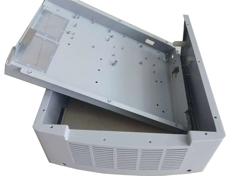
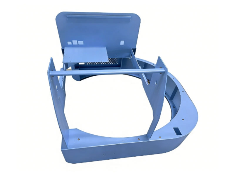
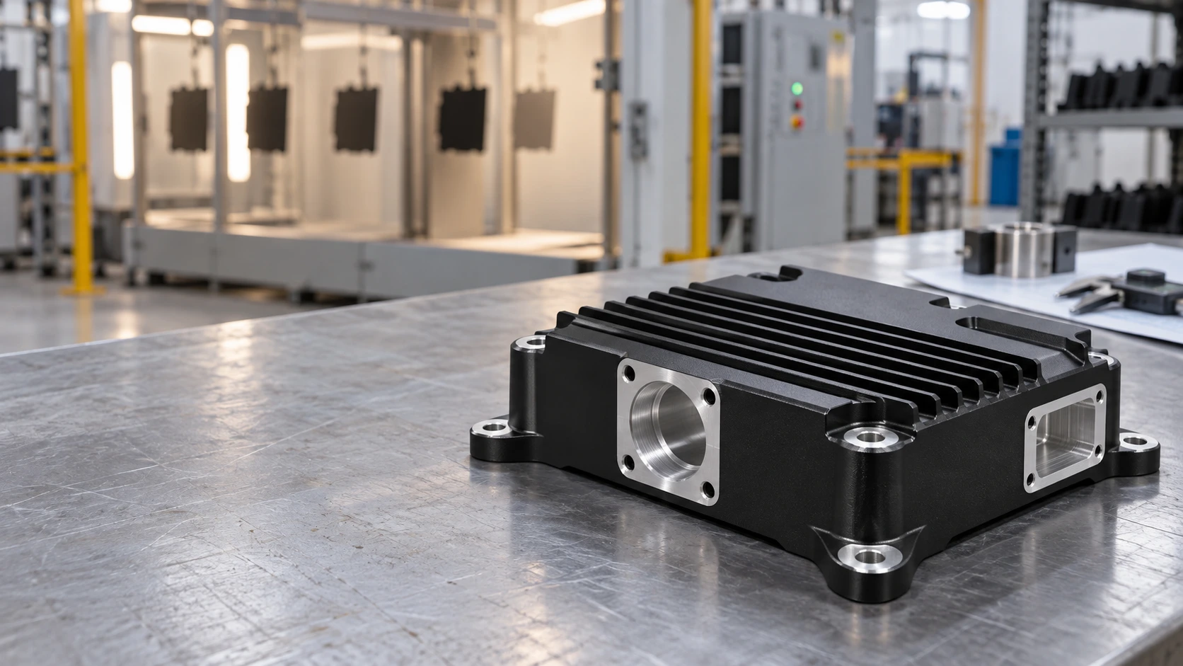
Medical and industrial equipment chassis assembly with cooling grilles and internal mounting rails

An industrial equipment chassis with cooling grilles and internal mounting rails shows how ventilation features, filters, supports, modular access, and assembly must be planned together. The referenced CK Metal Tech product serves medical, industrial testing, and communication applications, so it is a structural example rather than an AI rack performance claim.

Prepare the Cabinet for Cooling Components and Service Access

Plan Interfaces for Manifolds, Hoses, Fans, and Rear-Door Systems

A liquid-ready rack may need adjustable manifold brackets, controlled hose bend space, protected quick-connect locations, and separation between coolant paths and sensitive electrical areas. A rear-door heat exchanger or fan-assisted door may add weight to the hinge side and change rear service clearance.

Include component interface drawings, estimated weight, connection direction, removal path, and responsibility for brackets or purchased hardware. Adjustable interfaces may suit an evolving cooling system, but excessive adjustability can reduce stiffness and complicate repeat assembly.

Design Removable Panels for Maintenance, Inspection, and Replacement

Doors and panels should provide access without forcing technicians to disconnect unrelated cables or coolant lines. Review tool clearance, lifting method, panel weight, fastener retention, grounding continuity, and the sequence for removing a manifold, PDU, fan unit, or server.

More removable panels are not automatically better. Each joint can introduce alignment variation, leakage paths, and grounding requirements. Use removable construction where it supports real maintenance tasks and fixed structure where rigidity matters more.

Apply Sheet Metal DFM and Validate the Prototype

Control Bending, Welding, Fasteners, Tolerances, and Grounding Surfaces

Bend variation, weld shrinkage, hardware position, panel flatness, and coating buildup can combine into door, rail, or equipment-alignment problems. Drawings should identify functional datums, assembly-sensitive interfaces, grounding surfaces, masked threads, and dimensions that apply after finishing.

CK Metal Tech’s precision sheet metal manufacturing capabilities include CNC laser cutting, punching, bending, riveting, welding, grinding, and processing of several industrial sheet materials. Suitability depends on the drawing, dimensions, material, quantity, and inspection requirements. Buyers can also review powder coating vs wet painting for sheet metal parts when defining cosmetic areas, masking, grounding points, corrosion expectations, and assembly interfaces.

Validate Structure, Fit, Airflow, and Transport Before Repeat Production

Prototype approval should cover more than individual dimensions. A representative build may need rail alignment, door operation, panel fit, grounding continuity, equipment installation, cable routing, cooling-component clearance, and packaging review. Structural, airflow, and thermal testing responsibilities must be agreed before the order because a fabrication supplier may build to validated drawings without providing facility-level thermal engineering.

Before repeat production, freeze approved revisions, fixtures, inspection points, purchased components, packaging, and change-control rules. A successful hand-built sample does not prove repeatability without a defined production process.

Prepare the RFQ and Qualify a Sheet Metal Rack Manufacturer

Include the Technical Inputs Needed for a Comparable Quote

A custom server rack RFQ should include:

  • Controlled 2D drawings, 3D models, BOM, and revision status
  • Dimensions, equipment layout, rail interfaces, and component weights
  • Static, service, anchoring, lifting, and transport conditions
  • Air, liquid-ready, or hybrid cooling architecture
  • Door, cable, PDU, fan, filter, and manifold requirements
  • Material, finish, grounding, masking, and cosmetic specifications
  • Prototype quantity, production volume, inspection, assembly, and packaging scope

When the design is not frozen, request a DFM and prototype quotation rather than a production price based on unresolved assumptions.

Evaluate Supplier Capabilities, Evidence, and Red Flags

A qualified data center cabinet manufacturer should explain how cutting, bending, joining, finishing, inspection, trial assembly, and packaging remain controlled. Ask how functional datums are maintained, how cabinet-level fit is checked, which processes are subcontracted, and how revisions reach production.

Red flags include quotations without a revision, vague load assumptions, no review of cooling hardware, and no cabinet-level assembly check. Zhejiang Chuangkai Mechanical and Electrical Technology Co., Ltd., operating as CK Metal Tech, combines sheet metal processing, machining, stamping, surface finishing, and assembly through its интегрированные возможности высокоточного металлообработки. Each AI server rack or data center cabinet still requires project-specific review.

Заключение

A reliable AI server rack begins with a defined load path, controlled airflow, confirmed cooling interfaces, service access, and a manufacturing plan that accounts for bending, welding, hardware, finishing, and assembly. Generic sheet thickness, perforation percentages, or “liquid-ready” labels cannot replace application-specific review.

Buyers can submit drawings for a custom server cabinet manufacturing review with the 2D drawings, 3D model, BOM, dimensions, material, equipment weight, cooling configuration, target quantity, inspection scope, and packaging requirements. CK Metal Tech can then assess the requested route against its available fabrication and assembly processes.

Часто задаваемые вопросы

How do I select sheet metal thickness for an AI server rack?

Thickness depends on the load path, unsupported span, openings, formed geometry, joint type, equipment weight, service conditions, and transport method. Review local deflection and interface stability rather than selecting thickness from total weight alone.

Does every AI server rack need liquid cooling?

No. The suitable architecture depends on heat output, rack density, facility conditions, server design, and operating plan. Air-cooled, liquid-ready, and hybrid configurations require different mechanical interfaces.

How can a server cabinet reduce hot-air recirculation?

Align intake and exhaust openings with the equipment, close unused rack spaces, reduce bypass gaps, keep cables and accessories out of the exhaust path, and coordinate the cabinet with aisle-level air management.

What information is needed for a custom server rack quote?

Provide drawings, BOM, dimensions, equipment layout and weight, cooling architecture, rail and accessory interfaces, material, finish, grounding, masking, quantities, inspection, assembly, and packaging requirements.

How do I choose a data center cabinet manufacturer?

Evaluate the manufacturing route, datum control, joining methods, finishing, cabinet-level assembly, inspection evidence, revision control, subcontractor management, prototype-to-production planning, and technical communication.

14th Август 2026

How to Source Semiconductor Equipment Frames and Enclosures: Supplier Qualification and RFQ Checklist


How to Source Semiconductor Equipment Frames and Enclosures Supplier Qualification and RFQ Checklist

Choosing a semiconductor equipment frame supplier requires more than comparing prices. A frame or enclosure may meet individual dimensions yet still create problems when doors, rails, panels, and internal modules are assembled. Buyers must connect design intent, manufacturing route, inspection, revision control, and capacity. This guide explains how to prepare a quote-ready RFQ, qualify a semiconductor equipment enclosure manufacturer, reduce dimensional and finishing risks, and select a supplier for prototype, NPI, or repeat production.

Define the Frame and Enclosure Scope Before Sending an RFQ

Distinguish Frames, Enclosures, Chassis, and Process Chambers

A welded frame normally carries loads and establishes equipment geometry. A sheet metal enclosure protects internal components and may include doors, removable panels, ventilation features, mounting rails, cable openings, and grounding points.

Process chambers are different because vacuum, process gases, controlled atmospheres, or special cleanliness requirements may demand capabilities beyond structural fabrication. The RFQ should separate manufactured parts, purchased components, customer-supplied items, and final assembly duties, including panel fitting, hardware installation, functional checks, and module-level packaging.

This distinction prevents a common sourcing error: selecting a capable general fabricator for a component that requires application-specific sealing, cleanliness, or validation. It also prevents missing costs when a quoted frame excludes the panels, hardware, purchased items, or assembly work needed to make it usable.

Identify Functional Datums, Interfaces, Loads, and Conditions

“High precision” is not a usable purchasing specification. Engineering teams should identify the surfaces, holes, rails, and interfaces that control installation or performance. These may include base mounting points, module interfaces, door openings, grounding surfaces, and alignment features.

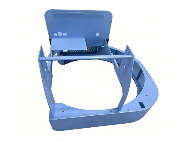
The suitable structure depends on size, load, stiffness, weight, corrosion exposure, service access, and finishing requirements. Welded steel, formed sheet metal, aluminum structures, machined bases, and cast iron assemblies suit different conditions. A wafer dicing equipment cast iron frame assembly, for example, should be reviewed as a combined route involving structure, machined interfaces, inspection, and assembly rather than as a generic metal part.


Wafer dicing equipment cast iron frame assembly for semiconductor equipment

Before requesting quotations, buyers should confirm which features are functional datums, which surfaces contact other modules, and whether the supplier must verify the completed assembly rather than individual components.

Build a Quote-Ready Semiconductor Equipment Enclosure RFQ

Provide Controlled Drawings, Models, BOMs, and Revisions

A useful semiconductor equipment enclosure RFQ should include current 2D drawings, 3D models when available, a BOM, revision status, material requirements, and expected quantities. The 2D drawing should control tolerances, datums, finishes, inspection notes, and special requirements.

Identify the controlling file and require the quotation to state the reviewed revision. Customer-supplied parts, standard hardware, and supplier-purchased items must be marked clearly. Otherwise, two suppliers may appear to quote the same assembly while including different materials, fasteners, finishing operations, or inspection work.

When a design is still changing, request a DFM review and prototype quotation before asking for a firm production price. This allows the supplier to identify inaccessible welds, difficult bend sequences, coating conflicts, uncertain datums, and features that may require machining after fabrication.

Specify CTQs, Finish, Inspection, Volumes, and Packaging

Critical-to-quality characteristics should relate to function. Tightening every dimension may raise cost without improving assembly, while leaving mounting interfaces undefined can make a compliant frame unusable.

State prototype quantity, batch size, annual demand, material, surface finish, cosmetic zones, masking areas, grounding points, inspection records, labeling, and packaging. The supplier should know whether dimensions apply before or after coating and which threads, electrical contact areas, locating surfaces, or slots must remain free of buildup.

Packaging also belongs in the RFQ. Large frames may require defined lifting and restraint, while finished panels need protection against rubbing, edge impact, moisture, or mixed-part contact. These details help suppliers quote comparable scopes instead of hiding different assumptions behind different unit prices.

Evaluate the Supplier’s Complete Manufacturing Route

Review Structural Fabrication and Machined Interfaces

A semiconductor equipment frame manufacturer should explain the route from raw material to approved assembly. For a welded structure, that may include cutting, fixture setup, welding sequence, intermediate checks, correction, post-weld machining where needed, surface finishing, dimensional inspection, and trial assembly.

Ask how datums are established before welding, protected during fabrication, and verified afterward. Post-weld machining may be appropriate when welding cannot reliably hold a mounting surface or hole pattern, but it is not required for every design. The decision depends on structure, tolerance, access, and risk.

Critical outsourced operations should also be disclosed. Outsourcing is not automatically unsuitable, but the main supplier should explain specification control, batch identification, incoming verification, and responsibility for nonconforming work. The quotation should cover the completed manufacturing route rather than only the processes performed in-house.

Verify Enclosure Fabrication, Finishing, and Assembly

For equipment housings, check whether the supplier can connect cutting, bending, hardware insertion, welding, grinding, finishing, and assembly. CK Metal Tech’s precision sheet metal manufacturing capabilities include laser cutting, CNC punching, bending, riveting, welding, grinding, and processing of several commonly used industrial sheet materials. Suitability still depends on the drawing, material, size, finish, and inspection plan.

Buyers should confirm when doors, panels, hinges, rails, fasteners, and internal mounting features will be trial-fitted. Features affected by coating should be reviewed before finishing. Shipping separate parts without checking the assembled condition may transfer tolerance and fit problems to the equipment builder.

Where possible, prototype approval should include representative internal components or checking fixtures. This reveals whether the enclosure functions as an assembly, not merely whether each component passes an isolated measurement.

Prevent Distortion, Misalignment, and Assembly Failures

Control Weld Distortion and Protect Functional Datums

Welding creates local heating and uneven contraction. Joint layout, material thickness, restraint, and sequence can cause twisting, bowing, or movement at mounting interfaces.

Buyers should ask how fixtures locate the structure, how the welding sequence balances heat input, and which dimensions are checked before and after finishing. First-article inspection should prioritize mounting planes, hole patterns, diagonals, rail interfaces, and features that connect to other modules.

If final correction is the main control method, ask how it affects repeatability and whether the fixture, sequence, joint design, or machining plan needs revision. Correction may produce an acceptable prototype without proving that the same route will remain stable across repeat batches.

A suitable supplier should be able to connect the drawing’s functional requirements with a practical fabrication and measurement plan.

Prevent Tolerance Stack-Up and Coating Interference

Assembly problems often result from several small deviations rather than one defective part. Bend location, bend angle, welded position, inserted hardware, hole size, and coating buildup can accumulate across an enclosure.

Doors may rub, rails may shift, modules may not align, or grounding points may become insulated. Drawings should distinguish finished dimensions from pre-coating dimensions and identify masked areas, threaded holes, contact surfaces, and assembly-sensitive slots.

Prototype approval should include fitting of doors, panels, hardware, and representative internal components where practical. For repeated interfaces, review tolerance accumulation instead of tightening every feature. Adjustment slots, locating tabs, machined references, or controlled assembly points may provide a more stable solution than imposing excessive tolerances on all sheet metal dimensions.

Verify Inspection, Traceability, and Engineering Changes

Define Evidence and Control Nonconformance

Inspection requirements should match risk. A first article may include a dimensional report, material records, finish verification, photographs, or CMM data for selected features. The RFQ should identify full-report, sampling, and functional-check requirements.

For large structures that cannot be measured in one setup, review the proposed method before production. The supplier should explain how separate measurements maintain a reliable relationship to the defined datums.

Supplier qualification should also confirm how obsolete drawings are removed, batches are identified, and deviations, substitutions, rework, or repairs receive approval. Engineering changes may affect finished inventory, work in process, purchased components, fixtures, inspection programs, and packaging documents.

SEMI describes standards as technical agreements used in purchase specifications and equipment evaluations, while traceability is an established SEMI standards subject. This supports defining project-specific documentation rather than assuming that the word “semiconductor” creates one universal inspection package.

Compare Suppliers Before Awarding the Order

A supplier that produces one acceptable prototype may not be ready for repeat production. NPI needs engineering communication and flexible planning; repeat production adds fixture control, stable inspection, capacity planning, subcontractor control, and disciplined change management. Compare the complete route, not only unit price.

Qualification Area What the Buyer Should Confirm
Application fit Similar size, material, processes, and assembly risk
Manufacturing route Clear sequence through fabrication, finishing, inspection, and packaging
Datum control Method for protecting and measuring functional interfaces
Quality evidence Appropriate first-article, material, finish, and inspection records
Change control Revision, deviation, rework, and obsolete-inventory procedures
Capacity Fit for prototype, pilot batch, and expected repeat demand
Коммуникация Technical contact and documented review of assumptions

Red flags include vague answers about datums, excluded critical processes, uncontrolled subcontracting, missing revision references, and no trial-assembly plan. Depending on project risk, the next step may be a technical review, supplier audit, first article, pilot batch, or production approval.

How CK Metal Tech Supports Frame and Enclosure Projects

Zhejiang Chuangkai Mechanical and Electrical Technology Co., Ltd., operating as CK Metal Tech, combines precision sheet metal processing, machining, metal stamping, surface treatment, and component assembly. Its интегрированные возможности высокоточного металлообработки can support build-to-print projects requiring connected fabrication steps, and the company website lists a wafer dicing equipment cast iron frame assembly among its products.

This capability range does not replace project qualification. Buyers should submit drawings, material, functional datums, finish, target quantity, inspection requirements, and operating conditions so CK Metal Tech can review whether the requested route fits the available processes and identify points requiring clarification.

Заключение

Successful semiconductor equipment frame sourcing starts with a controlled specification, not a supplier shortlist. Define the assembly boundary, functional datums, manufacturing route, finish, inspection evidence, change control, production stage, and packaging before comparing prices. A qualified supplier should explain how those requirements remain connected from first article through repeat production.

For a project-specific review, buyers can submit drawings and RFQ requirements to CK Metal Tech with the 2D drawing, 3D model, BOM, material, quantity, application, critical interfaces, finish, and inspection expectations. Samples or failure photographs can help focus the review.

Часто задаваемые вопросы

What files are needed to quote a semiconductor equipment frame?

Provide current 2D drawings, a 3D model when available, BOM, revision, material, finish, quantities, critical datums, inspection requirements, packaging, and delivery location. Identify the controlling document and explain unresolved assumptions.

Does every semiconductor equipment enclosure require cleanroom assembly?

No. It depends on installation location, exposure to sensitive processes, customer specifications, particle risk, and downstream assembly. Cleanliness, ESD controls, packaging, and permitted residues should be stated explicitly.

What tolerances should be specified for a welded equipment frame?

Focus on mounting planes, module interfaces, hole patterns, rails, and other functional datums. Wider limits may suit nonfunctional dimensions. The supplier should review whether welding, correction, or post-weld machining can hold each requirement.

When should a welded frame be machined after welding?

Post-weld machining may be suitable when critical mounting surfaces or hole locations cannot be held consistently through fabrication and correction alone. The decision depends on frame size, stiffness, access, tolerance, material, and measurement method.

How should buyers compare semiconductor equipment enclosure suppliers?

Compare drawing review, fabrication route, datum control, finishing, trial assembly, inspection records, revision control, capacity, subcontractors, packaging, and technical communication. Confirm essential operations and documents are included.

13th Август 2026

How to Control Runout in Long Shaft Machining: Setup, Grinding, and Inspection for Parts Up to 4 Meters


How to Control Runout in Long Shaft Machining Setup, Grinding, and Inspection for Parts Up to 4 Meters

Long shaft machining becomes difficult when a part passes diameter inspection but still shows excessive runout, bow, taper, vibration, or assembly misalignment. The cause may begin in the raw material, appear during stock removal, develop after heat treatment, or result from an inspection setup that does not reproduce the drawing datum. For shafts approaching four meters, material condition, workholding, machining sequence, grinding, inspection, and packaging must form one controlled process.

Long Shaft Machining Runout: Diagnose the Pattern First

Runout is commonly checked by rotating the shaft through 360 degrees and comparing the indicator’s maximum and minimum readings at a specified position. The result is meaningful only when the datum, support method, gauge position, and permitted value are defined.

Observed condition Check first Next action
Runout is concentrated near one end Center holes, chucking, tailstock, datum transfer Verify the setup axis
Maximum bow appears near the middle Support spacing, stock straightness, cutting force Review support and roughing
Diameter changes along the shaft Tailstock alignment, tool wear, thermal drift Separate geometric and thermal error
Runout increases after heat treatment Residual stress, support, remaining allowance Recheck straightness before finishing
Inspection reports disagree Datum, support points, orientation, gauge position Agree on one method

This identifies whether the next review should focus on material, setup, grinding, or measurement.

Why Long Shafts Develop Runout, Taper, and Straightness Errors

Material Straightness, Residual Stress, and Heat-Treatment Distortion

A long bar may contain initial bow or uneven residual stress. Heavy material removal can release that stress and move a shaft that appeared straight during roughing. Thin sections, keyways, and large diameter changes increase the risk.

For parts requiring substantial stock removal or heat treatment, a staged route may be safer than machining directly to final size. Rough turning establishes the geometry, followed by a stability or heat-treatment step when specified, another straightness check, and finish machining. Remaining allowance should be distributed so final turning or grinding does not need to correct most of the error from one side.

The RFQ should identify material grade, supply condition, heat treatment, hardness, and incoming straightness requirements.

Cutting Force, Unsupported Length, Clamping, and Heat

A slender shaft deflects under radial cutting force. As unsupported length increases, the tool may push the workpiece away, causing taper, barrel shape, chatter, or inconsistent diameter. Excessive chuck, tailstock, or steady-rest pressure can also bend the shaft before cutting.

Lower cutting force, short tool overhang, staged passes, controlled support, and temperature management reduce risk. A strategy that works on a rigid section may fail at the smallest diameter. Buyers should ask how the supplier will support that section, manage tool wear and thermal growth, and perform in-process checks.

Choosing the Right Setup for Long Shaft Turning

The setup should reflect shaft length, diameter, weight, material, critical datums, and permitted runout. Buyers can review CK Metal Tech’s long shaft CNC machining and grinding capabilities before submitting a drawing.

Between-Centers Turning and Tailstock Alignment

Turning between centers can preserve one rotational axis through several operations when center holes remain available as process datums. It is useful when multiple journals must relate to the same axis, although end geometry, weight, or feature access may require another setup.

Center holes must be prepared and protected because inconsistent seating transfers into runout. Tailstock alignment and thrust also matter: insufficient support permits movement, while excessive force may bow a slender shaft. The supplier should check initial indicator readings, explain how the part will be reloaded, and confirm whether center holes are temporary process features or drawing-controlled features.

Steady Rest vs. Follow Rest

A steady rest supports the shaft at a fixed position; a follow rest moves with the cutting tool. The correct choice depends on where the unsupported span develops.

Official machine guidance describes steady rests as support for long or narrow shafts and instructs operators to adjust rollers without causing workpiece deflection. It also recommends rotating the part and checking it with an indicator after adjustment.

Rollers that are too loose provide little control; rollers that are too tight can create friction, marks, heat, or artificial bending. The supplier should identify support locations and explain how alignment will be rechecked after repositioning.

Machining Sequence for Controlling Long-Shaft Runout

Rough Turning, Stability Review, and Finish Turning

A sound process separates heavy stock removal from final geometry control. Rough turning establishes the shape and reveals how the blank responds as material is removed. The shaft can then be checked for bow and datum movement before heat treatment, semi-finishing, or grinding.

A typical route is:

Material review → datum preparation → rough turning → stability or heat-treatment step → straightness review → semi-finishing → finish turning or grinding → final inspection.

The exact route depends on material, geometry, hardness, and drawing requirements. Repeated chucking should be minimized or controlled through consistent center holes, journals, or other process datums.

When Grinding Is Required—and When Turning Is Enough

Grinding may suit hardened journals, bearing fits, wear surfaces, or requirements involving surface condition, roundness, cylindricity, and relationships between diameters. It should not be added automatically. If finish turning meets the drawing, another setup may add cost and datum-transfer risk.


Precision shaft components manufactured with CNC turning and grinding processes for long shaft machining applications

For ground shafts, confirm the grinding datum, support method, allowance, heat-treatment sequence, and equipment range. CK Metal Tech’s прецизионно обработанные компоненты валов с шлифованием use a published route combining precision turning, grinding, and quenching for custom alloy-steel or stainless-steel designs.

This product does not establish a four-meter grinding range. Maximum length, diameter, weight, and geometry must be verified for each drawing.

How to Inspect Runout and Straightness on a Long Shaft

Define the Datum Axis Before Selecting the Gauge

Circular runout, total runout, straightness, roundness, and coaxial relationships describe different conditions. A shaft may meet diameter tolerance while failing rotational function. The drawing should identify the functional datum axis and the characteristic that affects assembly.

The datum may come from center holes, two bearing journals, or another functional feature. Measuring one section does not prove the complete shaft meets total runout or straightness requirements. Reports should state the datum, support method, gauge positions, orientation, rotation method, and result.

Control Gravity Sag and Measurement Support

A long slender shaft can sag under its own weight during horizontal inspection. Between-centers measurement, rollers, V-blocks, and coordinate measurement systems may produce different readings if support positions and datums are not correlated.

Inspection equipment must match the workpiece envelope, weight, access, and required uncertainty. A CMM may suit some features, but it should not be assumed that every machine can accommodate a complete four-meter shaft. Supplier and buyer should agree on support spacing, orientation, rotation method, and measurement correlation.

CK Metal Tech has CMM, 2.5D measurement, metallographic, and hardness-testing resources, but the method for a full-length four-meter shaft must be confirmed against the equipment range.

Troubleshooting Long-Shaft Machining Defects

Runout near one end points first to the chuck, center hole, tailstock, or datum transfer. Maximum bow near the middle suggests stock straightness, support spacing, cutting force, or stress release. Gradual taper calls for checks of alignment, tool wear, machine geometry, and temperature. Periodic chatter may indicate poor rigidity, unsuitable speed, excessive tool overhang, or unstable rest contact.

If runout increases after heat treatment, verify straightness before removing final allowance. If grinding introduces new error, review grinding heat, support pressure, wheel condition, and datum correlation. Rework should not begin until the cause and remaining allowance are understood.

RFQ Checklist for Long Shafts Up to 4 Meters

Drawing, Material, and Application Data

Provide the current 2D drawing and 3D model, total and effective machining lengths, maximum and minimum diameters, estimated weight, material grade and condition, center holes, functional datums, and all stepped, threaded, tapered, keyed, or drilled features.

State circular runout, total runout, straightness, surface requirements, heat treatment, hardness, grinding scope, and inspection records. Application details such as speed, load, mating components, and environment help identify critical features. Include quantities and any photographs or reports from an existing defect.

Capacity, Inspection, and Packaging Questions

Ask the supplier to confirm usable between-centers length, maximum diameter and weight, lifting method, tailstock and rest configuration, and which turning, heat treatment, grinding, and inspection stages are internal or outsourced. Confirm grinding range rather than assuming it matches turning capacity.

The quotation should identify datum simulation, inspection supports, sample and production setups, and packaging. A shaft that passes inspection can still bend if supported incorrectly during storage or transport.

How to Choose a Long Shaft Machining Supplier

Evaluate the Complete Manufacturing Route

A suitable supplier should explain how material review, datum preparation, roughing, support, heat treatment, finishing, grinding, inspection, and packaging connect. The review should identify where straightness is checked, how setups are repeated, which features establish the final axis, and what happens if the shaft moves after heat treatment.

Buyers should confirm whether first articles and production parts use the same route, which records are available, and how abnormal results are handled. Confirming machine length without discussing weight, support, grinding, and inspection is not a complete feasibility review.

Relevant CK Metal Tech Capabilities

Zhejiang Chuangkai Mechanical and Electrical Technology Co., Ltd. connects machining with related processes through its интегрированные возможности высокоточного металлообработки. Buyers can also review О компании Zhejiang Chuangkai Mechanical and Electrical Technology Co., Ltd. when evaluating the supplier.

Confirmed resources include 18 precision CNC lathes, turning capacity for workpieces up to approximately four meters, internal and external cylindrical grinding, centerless grinding, thread rolling, tapping, and drilling. CK Metal Tech also holds IATF 16949 certification, while its website presents machining, stamping, sheet-metal fabrication, surface treatment, and assembly as connected services.

Maximum diameter, weight, grinding length, support arrangement, and achievable runout or straightness must still be verified for each project.

Заключение

Controlling runout in long shaft machining requires more than a long-bed lathe. Material condition, datums, support pressure, cutting force, heat treatment, grinding, inspection, and transport must form one traceable route. The objective is to meet the drawing under an agreed measurement method, not to promise “zero runout.”

For a process review, submit the drawing, material, length, diameters, estimated weight, runout and straightness requirements, heat treatment, grinding scope, quantity, application, and any defect photographs or reports. Buyers can request a long shaft machining review от CK Metal Tech.

Часто задаваемые вопросы

How can runout be reduced when machining a long shaft?

Check raw-material straightness, datums, chuck and tailstock alignment, support location, cutting force, tool condition, and temperature. Separate roughing from finishing when stress release is likely, then inspect with the agreed datum and support method.

When is a steady rest required for long shaft turning?

A steady rest may be needed when the unsupported span permits deflection, vibration, or unstable size. The decision depends on diameter, length, weight, material, cutting force, geometry, and tolerance.

Should a long shaft be ground after CNC turning?

Grinding is appropriate when hardness, bearing fits, wear surfaces, roundness, cylindricity, or surface requirements cannot be met reliably by turning. It may be unnecessary when finish turning satisfies the drawing.

How is total runout measured on a four-meter shaft?

Define the datum axis, support arrangement, rotation method, and measurement locations. The method must consider gravity sag, equipment range, and correlation between supplier and customer inspection.

What information is needed for a long shaft machining quote?

Provide drawings, material condition, length, diameters, weight, datums, runout and straightness tolerances, surface requirements, heat treatment, grinding, features, quantities, application, inspection records, and packaging expectations.

7th Август 2026

3-Axis vs 4-Axis CNC Machining: When Does a Rotary Axis Reduce Setups and Datum Error?


3-Axis vs 4-Axis CNC Machining When Does a Rotary Axis Reduce Setups and Datum Error

Choosing between 3-axis and 4-axis CNC machining should begin with the drawing, not the machine list. A rotary axis can expose several sides of a component without manual flipping, which may reduce fixture changes, repeated probing, and datum transfer. It does not automatically make every part more accurate or less expensive. The correct route depends on feature direction, tool access, cross-face tolerances, workholding, quantity, and inspection.

3-Axis or 4-Axis CNC Machining? Quick Decision Guide

Map every machined feature by direction, then identify which features must remain related to the same functional datum.

Decision factor 3-axis machining often fits 4-axis machining often fits
Feature direction One or two accessible directions Three or more sides or radial directions
Cross-face relationships Moderate or fixture-repeatable Tight relationships around a common datum
Rotary features Limited and easy to re-fixture Radial holes, circular slots, angular patterns
Quantity Prototype, low volume, changing design Stable pilot or repeat production
Setup plan One or two direct setups Several 3-axis setups can be consolidated

The process should be reviewed against the actual part, not specified only as “4-axis required.” Buyers can examine CK Metal Tech’s precision CNC machining capabilities when a drawing needs process review.

Choose 3-Axis Machining for Accessible, Single-Direction Features

Three-axis machining remains practical for plates, brackets, flanges, and simpler housings whose critical features are accessible from the top or one additional flipped orientation. A qualified flip fixture and probing can make a second setup repeatable enough for many drawings.

It is often more economical for prototypes, low quantities, or changing designs. Buyers should still ask how many times the part will be clamped, which datum is used, and where cross-face dimensions will be inspected.

Choose 4-Axis Machining for Multi-Sided or Rotary Features

Four-axis machining becomes more relevant when holes, slots, flats, or mounting faces are distributed around a part, or when cylindrical features require controlled angular spacing. Rotating the workpiece can give the tool access to several directions while preserving one primary clamping relationship.

Autodesk identifies multi-sided, cylindrical, and wrapped geometry as common 4-axis applications and notes that less re-clamping can reduce cumulative setup error. Undercuts or compound angles may still require 5-axis machining or another process.

How Multiple Setups Create Datum Shift and Positional Error

Re-Clamping, Re-Zeroing, and Fixture Stack-Up

Every new setup introduces variables such as debris under a locator, fixture error, clamping deformation, probe variation, work offsets, and inconsistent seating. Their combined effect can appear in features produced from different setups.

A part may pass individual checks yet fail cross-face position, perpendicularity, or center distance. Multiple setups remain acceptable when tolerance and fixture repeatability support them. Clear datums, probing, and first-article checks reduce risk.

Why 4-Axis Machining Reduces—but Does Not Eliminate—Error

Keeping the part clamped while it indexes removes some manual handling and repeated zero-setting. Autodesk describes this as a reason 4-axis machining can reduce misalignment and cumulative tolerance error.

The rotary setup still has an error chain. The workpiece must match the rotation center; the fixture must resist eccentric loading; and indexing, offsets, heat, and clamping must be controlled. Autodesk support identifies an incorrect work-coordinate position relative to the rotary center as a cause of wrong 4-axis output.

Part Geometry and GD&T Requirements That Drive Axis Selection

Multi-Sided Holes, Slots, Flats, and Mounting Features

Strong 4-axis candidates often contain features on adjacent or opposite faces that share a critical relationship. Examples include mounting holes around a housing, flats indexed at specified angles, or several faces referenced to one bore.

The drawing should identify which features control assembly. Position, perpendicularity, parallelism, and profile across faces may justify one rotary setup. If these relationships are loose, a 3-axis flip fixture may be sufficient. Buyers should mark cross-face critical dimensions and ask how each will be produced and measured.

Cylindrical, Wrapped, and Repeating Angular Features

Radial holes, circumferential grooves, engraving, and angular patterns are natural rotary-axis applications. Indexed machining positions the workpiece at defined angles; wrapped or simultaneous motion may be needed for a continuous path around a cylinder.


Four-axis CNC machined motor housing with annular cooling grooves for multi-sided machining applications

A relevant example is a four-axis CNC-machined motor housing made from high-strength aluminum alloy. Its published annular cooling grooves and mounting holes illustrate why rotary access may suit cylindrical and installation features. The page does not provide setup savings or tolerance comparisons.

Indexed 3+1 vs Simultaneous 4-Axis Machining

When Indexed 4-Axis Machining Is Sufficient

In indexed, or 3+1, machining, the rotary axis moves the part to a fixed angle and stops. Standard 3-axis toolpaths then machine that orientation. Autodesk separates this method from continuous rotary cutting.

It suits bolt patterns, radial holes, flats, pockets, and mounting features at known angles. It is generally easier to program and inspect than simultaneous motion. A quote should state indexed positions, feature groups, support, and remaining setups.

When Simultaneous Rotary Motion Is Required

Simultaneous 4-axis machining moves the rotary axis while cutting. It may fit helical grooves, wrapped contours, or free-form cylindrical surfaces that cannot be produced efficiently by fixed indexing. Autodesk notes that these workflows require rotary-orientation control, clearance planning, and collision avoidance.

The machine configuration, CAM strategy, postprocessor, rotary direction, and collision model must agree. Not every “4-axis” machine supports the same continuous strategies. Buyers should specify the required geometry rather than demand simultaneous motion by default.

3-Axis vs 4-Axis CNC Machining Cost

Compare Completed-Part Cost, Not Machine Hourly Rate

A 4-axis machine may have a higher hourly rate, but the completed part may cost less if it replaces fixtures, setups, transfers, and intermediate inspection. A simple component may cost more because of added programming, alignment, and workholding.

A fair comparison includes programming, fixtures, setup labor, cycle time, tooling, inspection, first-article approval, and rework risk. Separate one-time charges from recurring unit costs, and require the same finished scope.

Prototype, Pilot, and Repeat Production Decisions

A prototype may be produced efficiently in two 3-axis setups while the design is changing. After interfaces and quantities stabilize, a rotary fixture may become worthwhile for pilot or repeat production. The break point depends on fixture cost, setup time, inspection effort, geometry, and lifetime quantity.

Changing the route can alter datum flow, tool marks, burr location, and measurement. If prototype and production methods differ, critical characteristics need renewed pilot-run validation.

Common 4-Axis Machining Risks and How to Prevent Them

Rotary Centerline, Workholding, and Orientation Errors

If the programmed coordinate system does not match the actual rotary centerline, features can shift as the part turns. Fixture eccentricity may create changing tool engagement, vibration, and angular error. A reversed rotary direction or incorrect zero can mirror or misplace wrapped features.

Controls include probing the centerline, checking indicator readings, simulating the machine and fixture, verifying the postprocessor, and inspecting a first article at several angular positions.

Tool Access, Collision, Rigidity, and Part Deformation

Rotating the part changes the collision environment. A tool, holder, spindle, chuck, fixture, or tailstock that clears at zero degrees may interfere at another angle. Long tools may reduce rigidity and offset the benefit of fewer setups.

Thin-wall housings and long or eccentric parts can deform under rotary clamping. DFM should review clamping zones, support, tool reach, clearance, and material-removal sequence. Some features may remain safer as a separate 3-axis operation.

RFQ Checklist for a 3-Axis vs 4-Axis Process Review

Drawing, Datum, and Application Information

Provide the current 2D drawing and STEP file, material and condition, datum system, cross-face positional tolerances, angular features, cylindrical surfaces, surface requirements, and the features that control assembly. Include prototype quantity, annual demand, inspection documents, and packaging needs.

If an existing route is failing, attach its setup description, inspection report, and photographs of the nonconforming feature.

Setup, Fixture, and Inspection Questions

Ask each supplier to state:

  • The proposed number of setups
  • Whether the route is 3-axis, indexed 3+1, wrapped, or simultaneous 4-axis
  • Which features remain in one clamping
  • The rotary-axis direction and workholding concept
  • Whether auxiliary support is needed
  • How cross-face GD&T will be inspected
  • Whether samples and production use the same route
  • Which fixture and first-article charges are one-time costs

How to Choose a 3-Axis and 4-Axis CNC Machining Supplier

Verify the Process Plan, Not Only the Machine List

A machine list does not show whether a supplier can select the correct route. A useful review identifies feature directions, datum flow, tool access, fixture risk, and inspection before quotation.

Ask for a simplified setup map and the reason behind the axis selection. The supplier should recommend 3-axis machining when it is more direct and 4-axis machining when reduced handling creates an advantage. Confirm rotary-centerline and first-article controls.

Relevant CK Metal Tech Capabilities

Zhejiang Chuangkai Mechanical and Electrical Technology Co., Ltd., also known as CK Metal Tech, supports drawing-based projects through its интегрированные возможности высокоточного металлообработки. Confirmed resources include eight 4-axis CNC machines, four CNC milling machines, and 4-axis capacity for larger workpieces up to approximately 1.8 meters, subject to geometry, diameter, weight, fixture, and tool-access requirements.

The company also has CMM and 2.5D inspection resources and holds IATF 16949 certification. CK Metal Tech’s machining scope includes milling, turning, grinding, drilling, and related operations. Specific rotary mode, work envelope, positional capability, and inspection method should be verified against each drawing.

Заключение

The decision between 3-axis and 4-axis CNC machining should follow three steps: map the required machining directions, identify cross-face dimensions that depend on a common datum, and compare complete setup, fixture, programming, and inspection cost. A rotary axis can reduce re-clamping risk, but only when the centerline, workholding, program, and inspection plan are controlled.

Buyers can request a 3-axis vs 4-axis process review by submitting the drawing, STEP file, material, datum system, cross-face tolerances, circular features, quantity, and any existing setup or inspection report.

Часто задаваемые вопросы

Does 4-axis CNC machining always improve accuracy?

No. It can reduce manual re-clamping and datum transfer, but accuracy still depends on the rotary centerline, fixture, machine condition, work offsets, toolpath, heat, and inspection method.

When is 3-axis machining more cost-effective?

It is often more economical when features are accessible from one or two directions, quantities are low, the design is changing, and cross-face tolerances can be controlled with a direct fixture.

What is the difference between 3+1 and simultaneous 4-axis machining?

In 3+1 machining, the rotary axis positions the part and remains stationary during cutting. In simultaneous machining, the rotary axis moves continuously while the tool follows the programmed path.

Can a 3-axis machine produce multi-sided parts?

Yes. The part can be flipped or moved to another fixture. Suitability depends on setup count, fixture repeatability, cross-face tolerances, quantity, and datum-transfer risk.

What information is needed for a 4-axis CNC machining quote?

Provide drawings, a STEP file, material, datums, cross-face GD&T, radial or circular features, surface requirements, quantities, application details, and inspection expectations.

6th Август 2026

Швейцарская механическая обработка против токарной обработки на станках с ЧПУ: как выбрать для тонких валов, штифтов и деталей малого диаметра.

Швейцарская механическая обработка против токарной обработки на станках с ЧПУ: как выбрать оптимальный вариант для тонких валов, штифтов и деталей малого диаметра.


Выбор между швейцарской обработкой и традиционной токарно-станочной обработкой с ЧПУ становится сложным, когда чертеж содержит малый диаметр, длинный незакрепленный участок, жесткие требования к биению или второстепенные элементы. Выбор зависит от типа опоры, длины резания, состояния заготовки, сложности элемента, допуска и количества. Это руководство поможет инженерам и группам закупок оценить валы, штифты, втулки, соединители и другие тонкие детали, не полагаясь на фиксированные правила.

Швейцарская обработка на станках или токарная обработка на станках с ЧПУ? Краткое руководство по выбору.

Первое решение должно основываться на геометрических параметрах и рисках, связанных с технологическим процессом, а не на предположении, что станок швейцарского типа обеспечит большую точность. Покупатели могут ознакомиться с продукцией CK Metal Tech. Возможности высокоточной токарной обработки на станках с ЧПУ и швейцарской обработки. когда необходимо оценить оба маршрута.

Состояние проекта Швейцарская обработка часто является подходящим вариантом. Традиционная токарная обработка на станках с ЧПУ часто является подходящим вариантом.
Малый диаметр и длинная тонкая секция Поддержка может оставаться вблизи зоны среза. Возможно, если стратегия фиксации заготовки и резки контролирует отклонение.
Короткая, жесткая, простая деталь Может добавить ненужную настройку. Зачастую это более прямой маршрут.
Поперечные отверстия, плоские поверхности, канавки или обратная обработка Полезно, когда машина выполняет несколько операций одновременно. Практично, когда вторичная работа остается экономически выгодной.
Низкий или неопределенный объем Зависит от настроек и функций. Зачастую это проще обосновать.
Стабильное повторное производство Может сократить объем работы по перемещению грузов между операциями. Конкурентоспособен для более простой геометрии.
Переменная прямолинейность или диаметр стержня Заготовка должна соответствовать направляющей втулке. В зависимости от способа крепления заготовки, чувствительность может быть ниже.

Выбирайте швейцарскую обработку для изготовления деталей малого диаметра, тонких и многофункциональных деталей.

Швейцарская обработка обычно применяется в случаях, когда деталь изгибается или вибрирует при перемещении инструмента от основной точки зажима. При работе с направляющими втулками заготовка поддерживается вблизи зоны резания, в то время как передняя бабка подает материал через направляющую. Это позволяет уменьшить длину незакрепленного участка во время резки и подходит для длинных прецизионных штифтов, узких ступенчатых валов и деликатных деталей.

Это также полезно, когда можно комбинировать токарную обработку, поперечное сверление, фрезерование, нарезание резьбы или обратную обработку. Покупатели должны проверить фактическую конфигурацию станка. Токарный станок швейцарского типа может работать с направляющей втулкой или без нее, при этом количество приводного инструмента, функции вспомогательного шпинделя и размеры используемого прутка могут различаться. Опубликованные технические характеристики подтверждают, что универсальные токарные станки швейцарского типа могут поддерживать как работу с направляющей втулкой, так и работу с зажимным устройством.

Для изготовления коротких, крупных или простых деталей выбирайте традиционную токарную обработку на станках с ЧПУ.

Традиционная токарная обработка на станках с ЧПУ остается практичной для жестких деталей, простых наружных профилей, больших диаметров, небольших объемов или чертежей, которые могут меняться. Для короткого штифта с одним диаметром и простой резьбой швейцарская настройка может быть нецелесообразной.

Токарный станок с неподвижной передней бабкой также может производить тонкие детали с использованием поддержки задней бабки, люнетов, поэтапной резки и инструмента с малым усилием. Вопрос в том, обеспечивают ли эти меры стабильность деталей. Многократные корректировки, несколько настроек или непостоянное биение оправдывают пересмотр швейцарских методов обработки. Если деталь остается стабильной, замена оборудования может увеличить стоимость без улучшения качества.

Почему поддержка заготовки влияет на точность обработки тонких деталей?

Опора направляющей втулкой против зажимного устройства с неподвижной передней бабкой

Тонкий вал деформируется, когда радиальная сила резания действует на незакрепленный участок. Результатом может быть конусность, вибрация, изменение диаметра, плохая прямолинейность или неровная поверхность. Риск возрастает, если самый слабый участок находится далеко от патрона или содержит остаточные напряжения.

Направляющая втулка уменьшает расстояние между инструментом и опорой, но не устраняет износ инструмента, нагрев, неравномерность заготовки, зазоры или проблемы с последовательностью операций. Традиционная токарная обработка может оставаться подходящей, если задняя бабка или люнет поддерживают деталь, не блокируя ее элементы. Покупателям следует уточнить, как будет закреплена заготовка и используется ли в производстве аналогичная схема крепления.

Прямолинейность прутка, разброс диаметров и посадка направляющей втулки.

При обработке направляющих втулок диаметр прутка, его округлость, прямолинейность и состояние поверхности влияют на подачу и контакт. Чрезмерный зазор может ослабить опору; недостаточный зазор может вызвать трение, проблемы с подачей или появление царапин на поверхности.

Требования к запасам зависят от станка, материала, геометрии и режима работы. Некоторые швейцарские токарные станки с возможностью переоборудования могут работать без направляющей втулки и использовать тянутый пруток для более коротких деталей, в то время как для работы с направляющей втулкой может потребоваться более контролируемый запас материала. Информация о стали SS20 от Tsugami отличает традиционную работу с направляющей втулкой от дополнительной работы с зажимным устройством, показывая, почему в запросе предложений следует указывать состояние материала, а не только марку сплава.

Как геометрия детали и допуски определяют процесс правильной токарной обработки

Прецизионные валы, изготовленные с использованием токарной обработки, шлифовки и термообработки на станках с ЧПУ для промышленного применения.


Оцените диаметр, эффективную длину и отношение длины к диаметру одновременно.

Соотношение длины к диаметру полезно, но универсального отрезка, подходящего для каждой детали, не существует. Критической длиной может быть длина обработанной части, а не общая длина. На ступенчатом валу прогиб может определяться наименьшим диаметром или самой длинной слабой частью.

Проанализируйте минимальный диаметр, длину резания без опоры, радиусы перехода, толщину стенки, жесткость материала и доступ инструмента одновременно. Полая втулка может вести себя иначе, чем сплошной штифт с теми же внешними размерами. Отметьте базовые точки и участки, где изгиб или конусность могут повлиять на сборку, затем сравните опору, последовательность резания и возможную шлифовку.

Проверьте биение, прямолинейность и качество поверхности.

Допуск по диаметру не полностью определяет рабочие характеристики вала. Биение влияет на вращающиеся поверхности, прямолинейность влияет на соосность, а состояние поверхности может влиять на подшипники, уплотнения или контакт скольжения.

Свяжите каждое требование с функцией и укажите, как это следует измерять. Токарная обработка может напрямую создавать готовую деталь, но для некоторых компонентов после токарной обработки или термообработки требуется цилиндрическая или бесцентровая шлифовка. CK Metal Tech прецизионно обработанные компоненты валов с шлифованием На иллюстрации показан процесс, сочетающий в себе прецизионную токарную обработку, шлифовку и закалку для изготовления валов нестандартной конструкции, используемых в машиностроении и трансмиссионных системах.

Проверка поперечных отверстий, плоских поверхностей, канавок, резьбы и обратной стороны заготовки.

Мелкие детали часто обходятся дорого, поскольку для их изготовления требуется несколько операций. Поперечные отверстия, плоские поверхности, пазы, резьба, сверление торцов и элементы на срезе могут потребовать дополнительной обработки.

Правильно сконфигурированный швейцарский станок может выполнять несколько операций за один цикл, используя вращающийся инструмент и вспомогательный шпиндель. Это может сократить количество перемещений и изменений базовых точек, но удаление заусенцев, шлифовка или термообработка все равно могут снизить затраты. Попросите поставщика указать каждую операцию, базовую точку и этап контроля. Сравнивайте маршруты обработки готовых деталей, а не только время цикла.

Сравнение стоимости и объёма производства при обработке на швейцарских станках и токарной обработке на станках с ЧПУ.

Сравните затраты на настройку со стоимостью готовой детали.

Обработка на швейцарских станках может потребовать подготовки прутка, выбора направляющих втулок, большего количества инструментов и детального программирования. Традиционная токарная обработка может иметь более низкие затраты на настройку, но требует отдельного сверления, фрезерования, снятия заусенцев или обратной обработки.

Справедливое сравнение включает в себя материалы, настройку оборудования, время цикла, оснастку, потери остатков, вторичную обработку, шлифовку, термообработку, финишную обработку, контроль качества и упаковку. Убедитесь, что образцы и серийное производство используют один и тот же процесс. Низкая цена прототипа малоэффективна, если в дальнейшем для серийного производства потребуется новый технологический процесс.

Выберите процесс на этапах создания прототипа, пилотного производства и повторного выпуска продукции.

В процессе разработки прототипа может использоваться традиционная токарная обработка. После стабилизации геометрии и спроса швейцарская обработка может стать привлекательной, если она объединяет операции и сокращает объем погрузочно-разгрузочных работ. Однако сложная швейцарская установка может оставаться неэкономичной при низком уровне повторяющегося спроса.

Сравните сценарии с низким, ожидаемым и высоким объемом производства, разделяя разовые и периодические затраты. Рассмотрите, влияет ли изменение процесса на расположение заусенцев, следы от инструмента, базовые точки или производственные возможности. Поэтапный план — проверка конструкции, анализ процесса, пилотная партия, а затем утверждение производства — снижает риски.

Распространенные проблемы при токарной обработке и способы их предотвращения

Сужение, вибрация, отклонение и плохая прямолинейность

Эти дефекты не доказывают, что был выбран неправильный станок. Конусность может быть результатом деформации, износа, нагрева или неправильной центровки. Вибрация может возникать из-за недостаточной жесткости, неподходящего инструмента, агрессивных параметров или чрезмерной длины без опоры. Плохая прямолинейность может начинаться в заготовке, остаточных напряжениях, термообработке или последовательности резки.

Предоставьте поставщику данные измерений, показывающие, где возникают отклонения, дату проверки, информацию о партии, номер партии материала, а также информацию о том, возникает ли проблема постепенно или случайным образом. Стойкая нестабильность после проверки опор, оснастки и параметров может оправдать использование швейцарской обработки или шлифовки.

Следы от направляющих втулок, неравномерность заготовок, заусенцы и остатки материала.

Обработка на швейцарском станке сопряжена со своими рисками. Контакт с втулкой может оставлять следы на неподходящих поверхностях заготовок, поперечные отверстия могут оставлять заусенцы, чувствительные к сборке, а остатки материала могут повлиять на себестоимость мелкосерийного производства.

Перед утверждением определите внешний вид поверхности, пределы образования заусенцев, сколы кромок, условия резки и упаковку. Уточните, кто поставляет заготовку и какое состояние материала требуется. Эти детали предотвратят несоответствие деталей, имеющих приемлемые размеры, требованиям сборки или обработки.

Контрольный список для запроса коммерческого предложения на тонкие валы, штифты и детали малого диаметра

В полезное коммерческое предложение следует включить текущий 2D-чертеж и STEP-файл, материал и состояние, общую и эффективную длину резки, максимальный и минимальный диаметры, допуски по размерам и геометрии, требования к поверхности, характеристики, термообработку, качество отделки и количество.

Также необходимо уточнить записи о проверках, количество образцов, годовой спрос, область применения и упаковку. Длинные детали могут нуждаться в защите от изгиба при транспортировке. Уточните, включены ли в перечень услуг шлифовка, накатка резьбы, снятие заусенцев, термообработка и финишная обработка, и выясните предположения относительно наличия запасов или услуг сторонних подрядчиков.

Как выбрать поставщика оборудования для механической обработки и токарной обработки на станках с ЧПУ в Швейцарии

Поставщик должен объяснить, почему именно этот процесс подходит. Следует уточнить диапазон возможностей оборудования, режим работы, крепление заготовки, приводной инструмент, обратную обработку, вторичные процессы, контроль качества, а также средства контроля износа инструмента и отклонения заготовки. Не следует выбирать поставщика только потому, что в списке его возможностей указано «швейцарская обработка».

Компания Zhejiang Chuangkai Mechanical and Electrical Technology Co., Ltd. поддерживает проекты по изготовлению токарных деталей, располагая одним пятиосевым токарным станком швейцарского типа, 18 прецизионными токарными станками с ЧПУ, а также ресурсами для внутренней и внешней цилиндрической шлифовки, бесцентровой шлифовки, накатки резьбы, нарезания резьбы метчиком и сверления. интегрированные возможности высокоточного металлообработки охватывают взаимосвязанные производственные и сборочные процессы. Покупатели также могут ознакомиться с информацией по ссылке. О компании Zhejiang Chuangkai Mechanical and Electrical Technology Co., Ltd. При оценке своей деятельности компания CK Metal Tech указывает в числе своих услуг токарную обработку на станках с ЧПУ и обработку на швейцарских станках, а также имеет сертификат IATF 16949.

Заключение

Швейцарская обработка часто подходит для деталей малого диаметра, тонких и многофункциональных деталей, когда поддержка вблизи зоны резания и комбинированные операции снижают риски, связанные с качеством и обработкой. Традиционная токарная обработка на станках с ЧПУ остается практичной для более коротких, жестких, простых или мелкосерийных деталей. Выбор должен основываться на конечном этапе производства, а не на фиксированном диаметре, соотношении или количестве.

Для проверки технологического процесса предоставьте чертеж, информацию о материале, диаметрах, эффективной длине, критических допусках, характеристиках, термообработке, целевом количестве, области применения, а также фотографии или образцы любых дефектов. Покупатели могут запросить анализ обработки вала и штифта от CK Metal Tech.

Часто задаваемые вопросы

В чём основное различие между швейцарской обработкой и токарным станком с ЧПУ?

В швейцарских станках для механической обработки заготовок можно удерживать вблизи точки резания с помощью направляющей втулки, в то время как при традиционной токарной обработке заготовка обычно удерживается неподвижной передней бабкой. Некоторые станки швейцарского типа также могут работать без направляющей втулки.

В каких случаях для изготовления тонкого вала следует использовать швейцарскую обработку?

Учитывайте это, когда отклонение, вибрация, конусность или ряд второстепенных особенностей делают обычную токарную обработку нестабильной или дорогостоящей. Вместо того чтобы полагаться на одно соотношение, следует пересмотреть минимальный диаметр, эффективную длину, материал, допуски, характеристики и количество.

Действительно ли швейцарская обработка дороже, чем традиционная токарная обработка на станках с ЧПУ?

Настройка может быть более сложной, но сочетание токарной обработки, сверления, фрезерования и обратной обработки может снизить стоимость готовых деталей при серийном производстве. Простые детали или детали, изготавливаемые в небольших объемах, могут оставаться дешевле на обычном токарном станке.

Может ли обычный токарный станок с ЧПУ изготовить длинные прецизионные штифты?

Да, в зависимости от диаметра, материала, допуска, опоры, инструмента и стратегии резки. Постоянное отклонение или чрезмерная вторичная обработка могут быть предпочтительнее при использовании швейцарской обработки.

Какая информация необходима для получения коммерческого предложения на обработку деталей в Швейцарии?

Предоставьте чертежи, информацию о материале и состоянии, диаметрах, эффективной длине, допусках, биении, прямолинейности, требованиях к поверхности, характеристиках, термообработке, отделке, объеме проверки, упаковке и количестве.

31st Июль 2026

Обработка на станках с ЧПУ против штамповки металла: когда штамповочная оснастка оправдывает себя?


Обработка на станках с ЧПУ против штамповки металла: когда окупается использование штамповочного инструмента?

Выбор между обработкой на станках с ЧПУ и штамповкой металла — это не просто решение о цене за единицу продукции. Реальный вопрос заключается в том, оправдывают ли геометрия детали, зрелость конструкции, ожидаемый объем производства и срок службы использование специальной штамповочной матрицы. Обработка на станках с ЧПУ часто безопаснее для прототипов, неопределенного спроса, сплошной геометрии стержня или блока, а также деталей, которые могут изменяться. Штамповка металла становится более привлекательной, когда стабильная конструкция из листового металла будет повторяться достаточно долго, чтобы распределить инвестиции в оснастку между готовыми деталями. В некоторых случаях наименее рискованным решением является гибридный подход: штамповка базовой геометрии, а затем обработка только критически важных элементов.

Обработка на станках с ЧПУ, штамповка металла или гибридный процесс?

Состояние проекта Обработка на станках с ЧПУ Штамповка металла Гибридный маршрут
Вероятны изменения в дизайне. Плотная посадка Высокий риск, связанный с инструментами. Возможно после частичной заморозки проекта.
Спрос неопределенный Плотная посадка Сложно обосновать Полезно для производства мостов
Стабильный объем повторения Проанализируйте стоимость жизненного цикла. Сильный кандидат Сильный кандидат
Сплошная геометрия стержня или блока Плотная посадка Обычно не подходит Ограниченный
Геометрия листа или рулона Возможный Сильный кандидат Сильный кандидат
Прецизионные отверстия, резьба или базовые поверхности Плотная посадка Возможно, потребуется дополнительная работа. Часто практично

Продолжайте использовать станки с ЧПУ, если объемы производства или особенности конструкции неопределенны.

Обработка на станках с ЧПУ обычно целесообразна на этапах проверки функциональности, соответствия размерам, соответствия требованиям или окончательной геометрии изделия. Она позволяет вносить изменения без использования специального производственного штампа и создавать сложные элементы из листового, пруткового или блочного материала. Это делает её особенной. услуги по прецизионной обработке на станках с ЧПУ Это актуально для прототипов, опытных образцов, запасных частей и повторных заказов, объемы которых еще не позволяют амортизировать затраты на оснастку.

Подтвердите программное обеспечение, оснастку, выход материала, цены за партию, контроль качества и затраты на доработку. Механическая обработка может стать дорогостоящей, если каждая деталь требует длительного цикла или удаляет большую часть исходного материала. Однако она может оставаться правильной, если геометрию невозможно сформировать из листового материала, независимо от объема.

Инвестируйте в штамповочную оснастку, когда геометрия, спрос и конструкция стабильны.

Изготовление производственной оснастки становится целесообразным, когда деталь можно вырубить, проколоть, согнуть, сформировать или вытянуть из плоского проката, и при этом она вряд ли изменится. Штампы требуют первоначальных затрат, но повторное производство позволяет распределить эти инвестиции на протяжении всего проекта. На экономическую целесообразность влияют свойства материала, допуски и ожидаемый износ. Поздние изменения в конструкции могут потребовать существенной доработки штампов, поэтому функциональное тестирование и утверждение чертежей должны предшествовать выпуску оснастки.

Перед утверждением Услуги по прецизионной штамповке металла и изготовлению оснасткиЗапросите анализ технологичности производства, охватывающий материал, толщину, возможность формовки, критические размеры, вторичные операции, срок службы и статус доработки. Универсального порога производства, доказывающего окупаемость штамповки, не существует.

Используйте гибридный процесс, когда обработка требуется только для критически важных элементов.

Эти процессы не всегда являются конкурирующими вариантами. Штампованная заготовка может создавать внешний профиль, изгибы и формованные элементы, в то время как нарезание резьбы, развертывание, шлифовка или фрезерование завершают создание критически важного интерфейса.

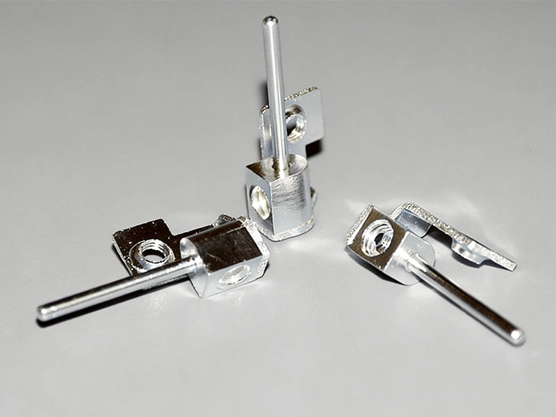
Этот метод наиболее эффективен, когда штампованная деталь обеспечивает повторяемые опорные точки, а вторичный цикл короткий. Он менее привлекателен, когда деформация при формовке делает оснастку нестабильной или большинство элементов все еще требуют механической обработки. Штампованный клеммный блок для печатной платы с дополнительной механической обработкой. Принцип действия демонстрируется на примере опубликованного технологического процесса, сочетающего в себе прецизионную штамповку, гибку, нарезание резьбы, сверление и гальваническое покрытие.


Клеммные колодки для печатных плат изготавливаются с помощью высокоточной штамповки, гибки, нарезания резьбы, сверления и вторичной механической обработки.

Почему штамповочная оснастка не всегда оправдывает себя

Учитывайте пожизненный спрос, изменения и скрытые операции.

Короткий жизненный цикл продукта, частые изменения, вносимые заказчиком, или неопределенный спрос могут привести к тому, что количество изготавливаемых деталей окажется недостаточным для окупаемости инвестиций в штампы. Вместо того чтобы полагаться на один оптимистичный годовой прогноз, следует моделировать низкие, ожидаемые и высокие объемы производства за весь срок службы.

В стоимость готовой штампованной детали должны входить: снятие заусенцев, нарезание резьбы, механическая обработка, очистка, гальваническое покрытие, контроль качества, сборка, упаковка, техническое обслуживание инструмента и возможные модификации. В коммерческом предложении следует указать, включены ли в стоимость испытания, выборочная проверка, доработки, заточка, запасные части, хранение и техническое обслуживание. Изменения после начала изготовления штампа могут увеличить стоимость и привести к задержкам, поэтому официальный выпуск оснастки является крайне важным этапом контроля.

Как рассчитать точку безубыточности для штамповочной оснастки

Сравните два полностью определенных производственных маршрута:

Точка безубыточности по объему производства = инвестиции в оснастку ÷ (стоимость готовой детали, изготовленной на станке с ЧПУ, − стоимость готовой детали, изготовленной методом штамповки)

Важно, чтобы изделие было готово. Стоимость станков с ЧПУ должна включать материалы, настройку, механическую обработку, инструменты, контроль качества, отделку и упаковку. Стоимость штамповки должна включать проектирование штампов, испытания, изготовление прессов, расход материалов, техническое обслуживание, вторичные операции, контроль качества, отделку и упаковку.

Если штампованная заготовка все еще требует обработки на станке с ЧПУ для создания отверстий и резьбы, используйте себестоимость готовой гибридной детали, а не цену только за прессование. Протестируйте несколько вариантов объемов производства. Небольшая разница в себестоимости единицы продукции обеспечивает длительный срок окупаемости; большая разница может оправдать более быструю окупаемость оснастки.

Попросите каждого участника тендера указать одинаковые параметры чертежа, материала, диапазоны количества, объем контроля, отделки, упаковки и условия владения инструментом. В противном случае, предложения могут охватывать разные виды работ. Правильный ответ на вопрос «Какой объем производства оправдывает использование штамповочного инструмента?» — это диапазон безубыточности для конкретного проекта, а не общеотраслевая цифра.

Подходит ли деталь, изготовленная на станке с ЧПУ, для штамповки по металлу?

Сначала определите, можно ли изготовить деталь нужной геометрии из листового или рулонного материала. Штамповка позволяет вырезать и формовать плоские заготовки, а механическая обработка удаляет материал из цельной заготовки. Толстые профили, закрытые элементы или сложная многоплоскостная геометрия могут быть не изготовлены напрямую.

Отделение штампуемых элементов от критически важных элементов, обрабатываемых механическим способом.

Начните с исходной формы. Может ли функциональность потребовать одинаковой толщины листа? Проанализируйте изгибы, глубину вытяжки, соотношение отверстий и кромок, упругое восстановление и поверхности, чувствительные к образованию заусенцев.

Разделите элементы чертежа на три группы: пригодные для штамповки, возможные после изменения конструкции или допусков, и все еще требующие механической обработки. Точные отверстия, глубокая резьба, уплотнительные поверхности, места крепления подшипников и базовые поверхности могут оставаться второстепенными операциями. Подтвердите базовые поверхности, припуск на механическую обработку и то, как отклонения в форме повлияют на окончательную настройку. Вторичная обработка на станках с ЧПУ обычно используется для высокоточных отверстий и монтажных поверхностей на штампованных деталях.

Как перейти от прототипирования на станках с ЧПУ к штампованному производству

Прототип, изготовленный на станке с ЧПУ, подтверждает функциональность, но не обязательно пригодность для штамповки. На чертеже могут присутствовать острые углы, переменная толщина или жесткие допуски, созданные для механической обработки, а не для формовки.

Зафиксируйте требования, затем используйте DFM и утверждение первой статьи.

Перед началом изготовления оснастки необходимо подтвердить материал, толщину, соединения, критические размеры, качество отделки и внесение изменений в чертежи. Проекты, в которых еще происходят функциональные изменения или изменения во взаимодействии с заказчиком, должны оставаться в гибком режиме до тех пор, пока не будут устранены основные риски.

Последовательность контролируемого перехода следующая: проверка прототипа, проектирование с учетом технологичности изготовления (DFM), пересмотр производственного чертежа, проектирование оснастки, испытание оснастки, проверка образцов, корректировка, утверждение первого образца, опытный запуск и выпуск в производство. Проверка образцов должна включать в себя оценку заусенцев, трещин, складок, упругого восстановления, состояния покрытия, внешнего вида и характеристик сборки, а не только размеров.

Что покупатели должны включить в запрос предложений по услугам штамповки на станках с ЧПУ

Для точного расчета стоимости необходимы актуальный 2D-чертеж и STEP-файл, информация о материале и форме заготовки, толщине, годовом и общем объеме производства, текущем технологическом процессе, критических допусках, финишной обработке, вторичной механической обработке, контроле качества, упаковке, а также известные изменения.

Также сравните стоимость владения инструментом, его хранения, технического обслуживания, заточки, запасных вставок, платы за модификацию, прав передачи и обработки по завершении программы. Низкая цена штампа может привести к дополнительным затратам в будущем, если не учитывать инженерные изменения или поддержку производства.

Выбор поставщика для перехода от станков с ЧПУ к штамповке.

Квалифицированный поставщик должен оценить оба варианта. Необходимо убедиться, что оснастка изготавливается внутри компании, что опытные и производственные группы несут совместную ответственность, что возможно скоординировать вторичные работы, а также как контролируется производство первых образцов, внесение изменений, износ оснастки и корректирующие действия.

Компания Zhejiang Chuangkai Mechanical and Electrical Technology Co., Ltd., также известная как CK Metal Tech, объединяет в своем ассортименте производство оснастки, штамповку металла, обработку на станках с ЧПУ, обработку поверхности, контроль качества и сборку. интегрированное высокоточное металлообрабатывающее производство Сфера деятельности. В числе подтвержденных ресурсов компании 8 четырехкоординатных станков с ЧПУ, 18 прецизионных токарных станков с ЧПУ и возможности обработки материалов швейцарского типа. CK Metal Tech также производит прогрессивную, вытяжную и комбинированную оснастку и имеет сертификат IATF 16949. Это позволяет проводить полный анализ маршрутов обработки на станках с ЧПУ, штамповку и гибридные процессы.

Заключение

Штамповка окупается, когда деталь действительно пригодна для штамповки, конструкция стабильна, а экономия в течение всего срока службы превышает затраты на оснастку, техническое обслуживание, проверку, вторичную обработку и риски внесения изменений. Обработка на станках с ЧПУ остается полезной для прототипов, изменяющихся конструкций, твердотельных геометрических форм и прецизионных элементов. Гибридный процесс может быть наиболее сбалансированным вариантом, когда базовую форму можно штамповать, но функциональные интерфейсы все еще требуют механической обработки.

Для проведения анализа проекта подготовьте актуальный чертеж, STEP-файл, информацию о материалах, целевом количестве, сроке службы, критических размерах, дополнительных операциях и требованиях к качеству. Эти детали позволят компании CK Metal Tech... Запросить анализ DFM (проектирование, проектирование, производство) для станков с ЧПУ и штамповки и сравнивать возможные маршруты, не требуя немедленного выделения средств на приобретение оборудования.

Часто задаваемые вопросы

Какой объём производства делает штамповку металла дешевле, чем обработка на станках с ЧПУ?

Универсального показателя не существует. Рассчитайте точку безубыточности, исходя из фактических инвестиций в оснастку и разницы между затратами на готовые изделия, изготовленные на станках с ЧПУ, и штамповочные изделия, включая техническое обслуживание, вторичную обработку, отделку, контроль качества и риски, связанные с изменением конструкции.

Можно ли напрямую преобразовать деталь, изготовленную на станке с ЧПУ, в деталь, отштампованную по металлу?

Иногда, но обычно не без учета DFM (проектирование для производства). Сплошные сечения, переменная толщина, глубокие элементы или жесткие допуски могут потребовать перепроектирования до начала изготовления оснастки.

Нужно ли по-прежнему обрабатывать штампованные детали на станках с ЧПУ?

Возможно. Резьба, прецизионные отверстия, подшипниковые посадки, уплотнительные поверхности, базовые поверхности или элементы с плотным креплением могут потребовать дополнительной механической обработки, сверления, нарезания резьбы, развертывания или шлифовки.

Как покупатель может определить, окупится ли приобретение штамповочного инструмента?

Подтвердите возможность штамповки, затем сравните затраты на весь жизненный цикл при низком, ожидаемом и высоком спросе. Аргументы более убедительны, когда проект зафиксирован, а скрытые операции включены в оба предложения.

Что следует проверить при выборе производителя штамповочного инструмента?

Проверка внутреннего проектирования оснастки, поддержки проектирования с учетом технологичности производства (DFM), испытаний, процедур изготовления первого образца, контроля версий, вторичной обработки, контроля качества, технического обслуживания оснастки, условий владения и управления качеством продукции.

30th Июль 2026

Есть ли у вас какой-нибудь дизайн?
Поддерживать

контакт
Дом
WhatsApp
Электронная почта
Контакты