CHUANGKAI

a i l a norte d

Cargando

     
hogar // blog

blog

Sheet Metal Design for AI Server Racks and Data Center Cabinets: Strength, Airflow, Cooling Integration and RFQ Checklist


Sheet Metal Design for AI Server Racks and Data Center Cabinets Strength, Airflow, Cooling Integration and RFQ Checklist

AI server rack design must connect structural strength, airflow, cooling hardware, service access, and sheet metal manufacturability before drawings are released for quotation. A cabinet may fit every listed component yet still fail if rails deflect, exhaust air recirculates, cables block the rear path, or a late-added coolant manifold interferes with removable panels. The practical goal is to convert equipment loads and cooling architecture into a buildable data center cabinet design, a testable prototype, and an RFQ that different suppliers can quote on the same basis.

Define the Rack, Cabinet, and Cooling Scope Before Designing the Sheet Metal Structure

Distinguish AI Server Racks, Data Center Cabinets, and Aisle Containment

An open rack mainly supports equipment, rails, power distribution, and cables. A cabinet adds doors, side panels, top panels, access control, and a more controlled internal air path. Aisle containment is a room-level airflow system and should not be confused with the cabinet.

Buyers should identify responsibility for rails, filters, blanking panels, PDU brackets, cable accessories, grounding hardware, and final assembly. A rack fabricator may not cover containment panels, facility ducting, or coolant distribution equipment. Without a clear boundary, suppliers may quote different products under the same description.

Translate Air-Cooled, Liquid-Ready, and Hybrid Cooling into Mechanical Requirements

An air-cooled rack needs an unobstructed inlet and exhaust route. A liquid-ready design may also require manifold brackets, hose routing, quick-connect access, drip-management provisions, and service clearance. A hybrid rack must accommodate both liquid hardware and residual air-cooled loads.

ASHRAE recommends matching cooling architecture and airflow management to AI rack density and treating power and cooling as connected design decisions. Before freezing the sheet metal geometry, confirm the cooling method, component envelopes, service direction, and responsibility for thermal validation.

Design the Structure Around the Actual Load Path

Define Static Load, Center of Gravity, Anchoring, and Transport Conditions

Total equipment weight is only the starting point. Door-mounted hardware, PDUs, cables, manifolds, rear cooling assemblies, and extended service trays can change local loading and stability. State whether the cabinet will remain fixed, move on casters, be anchored, or ship with equipment installed.

The RFQ should identify installation orientation, lifting points, floor interfaces, service extension conditions, and transport expectations. A structure suitable for stationary use may not be suitable for loaded shipment. Missing these inputs prevents a defensible decision about reinforcement, base geometry, or connection design.

Select Material, Sheet Thickness, Stiffeners, and Joint Types

Increasing sheet thickness is not the only way to raise stiffness. Folded edges, return flanges, formed ribs, localized supports, closed sections, and shorter unsupported spans may control deflection with less added mass. The right route depends on cabinet size, openings, load location, production volume, and shipping method.

Structural Route Suitable Use Main Purchasing Checks
Welded frame Fixed installation requiring rigidity Distortion, datum control, finish access
Bolted frame Modular design or shipment in sections Joint security, alignment, repeat assembly
Hybrid structure Rigid load path with removable modules Tolerance stack-up and interface control

Any thickness or reinforcement proposal should be checked against the actual load case rather than copied from a standard enclosure.

Create a Controlled Airflow Path Through the Cabinet

Design the Front-to-Rear Air Path, Doors, and Leakage Control

For front-to-rear-cooled equipment, the intake area should align with server inlets and the rear zone should remain clear. Perforated doors must balance open area with stiffness, hinge loading, security, and filtration. A universal perforation percentage is unsuitable because pressure drop depends on pattern, occupied area, equipment fans, and system configuration.

Unused rack positions and panel gaps can create bypass airflow. Define blanking requirements, door seals, side clearances, and filter arrangements. Assess the prototype as an assembled cabinet with representative doors, rails, and components, not as isolated sheet metal parts.

Prevent Recirculation, Cable Blockage, and Top-of-Rack Hot Spots

Hot exhaust can return through open rack spaces, gaps around doors, top openings, or congested rear zones. Cable bundles, PDUs, crossmembers, and cooling hoses may also restrict exhaust flow.

Blanking panels, baffles, disciplined cable routes, and clear exhaust zones can reduce cabinet-level recirculation, but they cannot correct an unsuitable room layout.


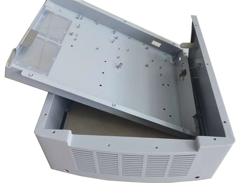
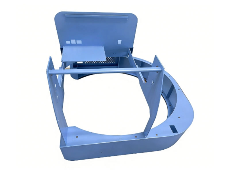
Medical and industrial equipment chassis assembly with cooling grilles and internal mounting rails

An industrial equipment chassis with cooling grilles and internal mounting rails shows how ventilation features, filters, supports, modular access, and assembly must be planned together. The referenced CK Metal Tech product serves medical, industrial testing, and communication applications, so it is a structural example rather than an AI rack performance claim.

Prepare the Cabinet for Cooling Components and Service Access

Plan Interfaces for Manifolds, Hoses, Fans, and Rear-Door Systems

A liquid-ready rack may need adjustable manifold brackets, controlled hose bend space, protected quick-connect locations, and separation between coolant paths and sensitive electrical areas. A rear-door heat exchanger or fan-assisted door may add weight to the hinge side and change rear service clearance.

Include component interface drawings, estimated weight, connection direction, removal path, and responsibility for brackets or purchased hardware. Adjustable interfaces may suit an evolving cooling system, but excessive adjustability can reduce stiffness and complicate repeat assembly.

Design Removable Panels for Maintenance, Inspection, and Replacement

Doors and panels should provide access without forcing technicians to disconnect unrelated cables or coolant lines. Review tool clearance, lifting method, panel weight, fastener retention, grounding continuity, and the sequence for removing a manifold, PDU, fan unit, or server.

More removable panels are not automatically better. Each joint can introduce alignment variation, leakage paths, and grounding requirements. Use removable construction where it supports real maintenance tasks and fixed structure where rigidity matters more.

Apply Sheet Metal DFM and Validate the Prototype

Control Bending, Welding, Fasteners, Tolerances, and Grounding Surfaces

Bend variation, weld shrinkage, hardware position, panel flatness, and coating buildup can combine into door, rail, or equipment-alignment problems. Drawings should identify functional datums, assembly-sensitive interfaces, grounding surfaces, masked threads, and dimensions that apply after finishing.

CK Metal Tech’s precision sheet metal manufacturing capabilities include CNC laser cutting, punching, bending, riveting, welding, grinding, and processing of several industrial sheet materials. Suitability depends on the drawing, dimensions, material, quantity, and inspection requirements. Buyers can also review powder coating vs wet painting for sheet metal parts when defining cosmetic areas, masking, grounding points, corrosion expectations, and assembly interfaces.

Validate Structure, Fit, Airflow, and Transport Before Repeat Production

Prototype approval should cover more than individual dimensions. A representative build may need rail alignment, door operation, panel fit, grounding continuity, equipment installation, cable routing, cooling-component clearance, and packaging review. Structural, airflow, and thermal testing responsibilities must be agreed before the order because a fabrication supplier may build to validated drawings without providing facility-level thermal engineering.

Before repeat production, freeze approved revisions, fixtures, inspection points, purchased components, packaging, and change-control rules. A successful hand-built sample does not prove repeatability without a defined production process.

Prepare the RFQ and Qualify a Sheet Metal Rack Manufacturer

Include the Technical Inputs Needed for a Comparable Quote

A custom server rack RFQ should include:

  • Controlled 2D drawings, 3D models, BOM, and revision status
  • Dimensions, equipment layout, rail interfaces, and component weights
  • Static, service, anchoring, lifting, and transport conditions
  • Air, liquid-ready, or hybrid cooling architecture
  • Door, cable, PDU, fan, filter, and manifold requirements
  • Material, finish, grounding, masking, and cosmetic specifications
  • Prototype quantity, production volume, inspection, assembly, and packaging scope

When the design is not frozen, request a DFM and prototype quotation rather than a production price based on unresolved assumptions.

Evaluate Supplier Capabilities, Evidence, and Red Flags

A qualified data center cabinet manufacturer should explain how cutting, bending, joining, finishing, inspection, trial assembly, and packaging remain controlled. Ask how functional datums are maintained, how cabinet-level fit is checked, which processes are subcontracted, and how revisions reach production.

Red flags include quotations without a revision, vague load assumptions, no review of cooling hardware, and no cabinet-level assembly check. Zhejiang Chuangkai Mechanical and Electrical Technology Co., Ltd., operating as CK Metal Tech, combines sheet metal processing, machining, stamping, surface finishing, and assembly through its capacidades integradas de fabricación de metales de precisión. Each AI server rack or data center cabinet still requires project-specific review.

Conclusión

A reliable AI server rack begins with a defined load path, controlled airflow, confirmed cooling interfaces, service access, and a manufacturing plan that accounts for bending, welding, hardware, finishing, and assembly. Generic sheet thickness, perforation percentages, or “liquid-ready” labels cannot replace application-specific review.

Buyers can submit drawings for a custom server cabinet manufacturing review with the 2D drawings, 3D model, BOM, dimensions, material, equipment weight, cooling configuration, target quantity, inspection scope, and packaging requirements. CK Metal Tech can then assess the requested route against its available fabrication and assembly processes.

Preguntas frecuentes

How do I select sheet metal thickness for an AI server rack?

Thickness depends on the load path, unsupported span, openings, formed geometry, joint type, equipment weight, service conditions, and transport method. Review local deflection and interface stability rather than selecting thickness from total weight alone.

Does every AI server rack need liquid cooling?

No. The suitable architecture depends on heat output, rack density, facility conditions, server design, and operating plan. Air-cooled, liquid-ready, and hybrid configurations require different mechanical interfaces.

How can a server cabinet reduce hot-air recirculation?

Align intake and exhaust openings with the equipment, close unused rack spaces, reduce bypass gaps, keep cables and accessories out of the exhaust path, and coordinate the cabinet with aisle-level air management.

What information is needed for a custom server rack quote?

Provide drawings, BOM, dimensions, equipment layout and weight, cooling architecture, rail and accessory interfaces, material, finish, grounding, masking, quantities, inspection, assembly, and packaging requirements.

How do I choose a data center cabinet manufacturer?

Evaluate the manufacturing route, datum control, joining methods, finishing, cabinet-level assembly, inspection evidence, revision control, subcontractor management, prototype-to-production planning, and technical communication.

14th agosto 2026

How to Source Semiconductor Equipment Frames and Enclosures: Supplier Qualification and RFQ Checklist


How to Source Semiconductor Equipment Frames and Enclosures Supplier Qualification and RFQ Checklist

Choosing a semiconductor equipment frame supplier requires more than comparing prices. A frame or enclosure may meet individual dimensions yet still create problems when doors, rails, panels, and internal modules are assembled. Buyers must connect design intent, manufacturing route, inspection, revision control, and capacity. This guide explains how to prepare a quote-ready RFQ, qualify a semiconductor equipment enclosure manufacturer, reduce dimensional and finishing risks, and select a supplier for prototype, NPI, or repeat production.

Define the Frame and Enclosure Scope Before Sending an RFQ

Distinguish Frames, Enclosures, Chassis, and Process Chambers

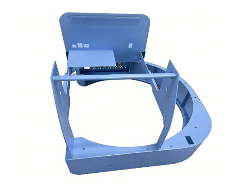
A welded frame normally carries loads and establishes equipment geometry. A sheet metal enclosure protects internal components and may include doors, removable panels, ventilation features, mounting rails, cable openings, and grounding points.

Process chambers are different because vacuum, process gases, controlled atmospheres, or special cleanliness requirements may demand capabilities beyond structural fabrication. The RFQ should separate manufactured parts, purchased components, customer-supplied items, and final assembly duties, including panel fitting, hardware installation, functional checks, and module-level packaging.

This distinction prevents a common sourcing error: selecting a capable general fabricator for a component that requires application-specific sealing, cleanliness, or validation. It also prevents missing costs when a quoted frame excludes the panels, hardware, purchased items, or assembly work needed to make it usable.

Identify Functional Datums, Interfaces, Loads, and Conditions

“High precision” is not a usable purchasing specification. Engineering teams should identify the surfaces, holes, rails, and interfaces that control installation or performance. These may include base mounting points, module interfaces, door openings, grounding surfaces, and alignment features.

The suitable structure depends on size, load, stiffness, weight, corrosion exposure, service access, and finishing requirements. Welded steel, formed sheet metal, aluminum structures, machined bases, and cast iron assemblies suit different conditions. A wafer dicing equipment cast iron frame assembly, for example, should be reviewed as a combined route involving structure, machined interfaces, inspection, and assembly rather than as a generic metal part.


Wafer dicing equipment cast iron frame assembly for semiconductor equipment

Before requesting quotations, buyers should confirm which features are functional datums, which surfaces contact other modules, and whether the supplier must verify the completed assembly rather than individual components.

Build a Quote-Ready Semiconductor Equipment Enclosure RFQ

Provide Controlled Drawings, Models, BOMs, and Revisions

A useful semiconductor equipment enclosure RFQ should include current 2D drawings, 3D models when available, a BOM, revision status, material requirements, and expected quantities. The 2D drawing should control tolerances, datums, finishes, inspection notes, and special requirements.

Identify the controlling file and require the quotation to state the reviewed revision. Customer-supplied parts, standard hardware, and supplier-purchased items must be marked clearly. Otherwise, two suppliers may appear to quote the same assembly while including different materials, fasteners, finishing operations, or inspection work.

When a design is still changing, request a DFM review and prototype quotation before asking for a firm production price. This allows the supplier to identify inaccessible welds, difficult bend sequences, coating conflicts, uncertain datums, and features that may require machining after fabrication.

Specify CTQs, Finish, Inspection, Volumes, and Packaging

Critical-to-quality characteristics should relate to function. Tightening every dimension may raise cost without improving assembly, while leaving mounting interfaces undefined can make a compliant frame unusable.

State prototype quantity, batch size, annual demand, material, surface finish, cosmetic zones, masking areas, grounding points, inspection records, labeling, and packaging. The supplier should know whether dimensions apply before or after coating and which threads, electrical contact areas, locating surfaces, or slots must remain free of buildup.

Packaging also belongs in the RFQ. Large frames may require defined lifting and restraint, while finished panels need protection against rubbing, edge impact, moisture, or mixed-part contact. These details help suppliers quote comparable scopes instead of hiding different assumptions behind different unit prices.

Evaluate the Supplier’s Complete Manufacturing Route

Review Structural Fabrication and Machined Interfaces

A semiconductor equipment frame manufacturer should explain the route from raw material to approved assembly. For a welded structure, that may include cutting, fixture setup, welding sequence, intermediate checks, correction, post-weld machining where needed, surface finishing, dimensional inspection, and trial assembly.

Ask how datums are established before welding, protected during fabrication, and verified afterward. Post-weld machining may be appropriate when welding cannot reliably hold a mounting surface or hole pattern, but it is not required for every design. The decision depends on structure, tolerance, access, and risk.

Critical outsourced operations should also be disclosed. Outsourcing is not automatically unsuitable, but the main supplier should explain specification control, batch identification, incoming verification, and responsibility for nonconforming work. The quotation should cover the completed manufacturing route rather than only the processes performed in-house.

Verify Enclosure Fabrication, Finishing, and Assembly

For equipment housings, check whether the supplier can connect cutting, bending, hardware insertion, welding, grinding, finishing, and assembly. CK Metal Tech’s precision sheet metal manufacturing capabilities include laser cutting, CNC punching, bending, riveting, welding, grinding, and processing of several commonly used industrial sheet materials. Suitability still depends on the drawing, material, size, finish, and inspection plan.

Buyers should confirm when doors, panels, hinges, rails, fasteners, and internal mounting features will be trial-fitted. Features affected by coating should be reviewed before finishing. Shipping separate parts without checking the assembled condition may transfer tolerance and fit problems to the equipment builder.

Where possible, prototype approval should include representative internal components or checking fixtures. This reveals whether the enclosure functions as an assembly, not merely whether each component passes an isolated measurement.

Prevent Distortion, Misalignment, and Assembly Failures

Control Weld Distortion and Protect Functional Datums

Welding creates local heating and uneven contraction. Joint layout, material thickness, restraint, and sequence can cause twisting, bowing, or movement at mounting interfaces.

Buyers should ask how fixtures locate the structure, how the welding sequence balances heat input, and which dimensions are checked before and after finishing. First-article inspection should prioritize mounting planes, hole patterns, diagonals, rail interfaces, and features that connect to other modules.

If final correction is the main control method, ask how it affects repeatability and whether the fixture, sequence, joint design, or machining plan needs revision. Correction may produce an acceptable prototype without proving that the same route will remain stable across repeat batches.

A suitable supplier should be able to connect the drawing’s functional requirements with a practical fabrication and measurement plan.

Prevent Tolerance Stack-Up and Coating Interference

Assembly problems often result from several small deviations rather than one defective part. Bend location, bend angle, welded position, inserted hardware, hole size, and coating buildup can accumulate across an enclosure.

Doors may rub, rails may shift, modules may not align, or grounding points may become insulated. Drawings should distinguish finished dimensions from pre-coating dimensions and identify masked areas, threaded holes, contact surfaces, and assembly-sensitive slots.

Prototype approval should include fitting of doors, panels, hardware, and representative internal components where practical. For repeated interfaces, review tolerance accumulation instead of tightening every feature. Adjustment slots, locating tabs, machined references, or controlled assembly points may provide a more stable solution than imposing excessive tolerances on all sheet metal dimensions.

Verify Inspection, Traceability, and Engineering Changes

Define Evidence and Control Nonconformance

Inspection requirements should match risk. A first article may include a dimensional report, material records, finish verification, photographs, or CMM data for selected features. The RFQ should identify full-report, sampling, and functional-check requirements.

For large structures that cannot be measured in one setup, review the proposed method before production. The supplier should explain how separate measurements maintain a reliable relationship to the defined datums.

Supplier qualification should also confirm how obsolete drawings are removed, batches are identified, and deviations, substitutions, rework, or repairs receive approval. Engineering changes may affect finished inventory, work in process, purchased components, fixtures, inspection programs, and packaging documents.

SEMI describes standards as technical agreements used in purchase specifications and equipment evaluations, while traceability is an established SEMI standards subject. This supports defining project-specific documentation rather than assuming that the word “semiconductor” creates one universal inspection package.

Compare Suppliers Before Awarding the Order

A supplier that produces one acceptable prototype may not be ready for repeat production. NPI needs engineering communication and flexible planning; repeat production adds fixture control, stable inspection, capacity planning, subcontractor control, and disciplined change management. Compare the complete route, not only unit price.

Qualification Area What the Buyer Should Confirm
Application fit Similar size, material, processes, and assembly risk
Manufacturing route Clear sequence through fabrication, finishing, inspection, and packaging
Datum control Method for protecting and measuring functional interfaces
Quality evidence Appropriate first-article, material, finish, and inspection records
Change control Revision, deviation, rework, and obsolete-inventory procedures
Capacity Fit for prototype, pilot batch, and expected repeat demand
Comunicación Technical contact and documented review of assumptions

Red flags include vague answers about datums, excluded critical processes, uncontrolled subcontracting, missing revision references, and no trial-assembly plan. Depending on project risk, the next step may be a technical review, supplier audit, first article, pilot batch, or production approval.

How CK Metal Tech Supports Frame and Enclosure Projects

Zhejiang Chuangkai Mechanical and Electrical Technology Co., Ltd., operating as CK Metal Tech, combines precision sheet metal processing, machining, metal stamping, surface treatment, and component assembly. Its capacidades integradas de fabricación de metales de precisión can support build-to-print projects requiring connected fabrication steps, and the company website lists a wafer dicing equipment cast iron frame assembly among its products.

This capability range does not replace project qualification. Buyers should submit drawings, material, functional datums, finish, target quantity, inspection requirements, and operating conditions so CK Metal Tech can review whether the requested route fits the available processes and identify points requiring clarification.

Conclusión

Successful semiconductor equipment frame sourcing starts with a controlled specification, not a supplier shortlist. Define the assembly boundary, functional datums, manufacturing route, finish, inspection evidence, change control, production stage, and packaging before comparing prices. A qualified supplier should explain how those requirements remain connected from first article through repeat production.

For a project-specific review, buyers can submit drawings and RFQ requirements to CK Metal Tech with the 2D drawing, 3D model, BOM, material, quantity, application, critical interfaces, finish, and inspection expectations. Samples or failure photographs can help focus the review.

Preguntas frecuentes

What files are needed to quote a semiconductor equipment frame?

Provide current 2D drawings, a 3D model when available, BOM, revision, material, finish, quantities, critical datums, inspection requirements, packaging, and delivery location. Identify the controlling document and explain unresolved assumptions.

Does every semiconductor equipment enclosure require cleanroom assembly?

No. It depends on installation location, exposure to sensitive processes, customer specifications, particle risk, and downstream assembly. Cleanliness, ESD controls, packaging, and permitted residues should be stated explicitly.

What tolerances should be specified for a welded equipment frame?

Focus on mounting planes, module interfaces, hole patterns, rails, and other functional datums. Wider limits may suit nonfunctional dimensions. The supplier should review whether welding, correction, or post-weld machining can hold each requirement.

When should a welded frame be machined after welding?

Post-weld machining may be suitable when critical mounting surfaces or hole locations cannot be held consistently through fabrication and correction alone. The decision depends on frame size, stiffness, access, tolerance, material, and measurement method.

How should buyers compare semiconductor equipment enclosure suppliers?

Compare drawing review, fabrication route, datum control, finishing, trial assembly, inspection records, revision control, capacity, subcontractors, packaging, and technical communication. Confirm essential operations and documents are included.

13th agosto 2026

How to Control Runout in Long Shaft Machining: Setup, Grinding, and Inspection for Parts Up to 4 Meters


How to Control Runout in Long Shaft Machining Setup, Grinding, and Inspection for Parts Up to 4 Meters

Long shaft machining becomes difficult when a part passes diameter inspection but still shows excessive runout, bow, taper, vibration, or assembly misalignment. The cause may begin in the raw material, appear during stock removal, develop after heat treatment, or result from an inspection setup that does not reproduce the drawing datum. For shafts approaching four meters, material condition, workholding, machining sequence, grinding, inspection, and packaging must form one controlled process.

Long Shaft Machining Runout: Diagnose the Pattern First

Runout is commonly checked by rotating the shaft through 360 degrees and comparing the indicator’s maximum and minimum readings at a specified position. The result is meaningful only when the datum, support method, gauge position, and permitted value are defined.

Observed condition Check first Next action
Runout is concentrated near one end Center holes, chucking, tailstock, datum transfer Verify the setup axis
Maximum bow appears near the middle Support spacing, stock straightness, cutting force Review support and roughing
Diameter changes along the shaft Tailstock alignment, tool wear, thermal drift Separate geometric and thermal error
Runout increases after heat treatment Residual stress, support, remaining allowance Recheck straightness before finishing
Inspection reports disagree Datum, support points, orientation, gauge position Agree on one method

This identifies whether the next review should focus on material, setup, grinding, or measurement.

Why Long Shafts Develop Runout, Taper, and Straightness Errors

Material Straightness, Residual Stress, and Heat-Treatment Distortion

A long bar may contain initial bow or uneven residual stress. Heavy material removal can release that stress and move a shaft that appeared straight during roughing. Thin sections, keyways, and large diameter changes increase the risk.

For parts requiring substantial stock removal or heat treatment, a staged route may be safer than machining directly to final size. Rough turning establishes the geometry, followed by a stability or heat-treatment step when specified, another straightness check, and finish machining. Remaining allowance should be distributed so final turning or grinding does not need to correct most of the error from one side.

The RFQ should identify material grade, supply condition, heat treatment, hardness, and incoming straightness requirements.

Cutting Force, Unsupported Length, Clamping, and Heat

A slender shaft deflects under radial cutting force. As unsupported length increases, the tool may push the workpiece away, causing taper, barrel shape, chatter, or inconsistent diameter. Excessive chuck, tailstock, or steady-rest pressure can also bend the shaft before cutting.

Lower cutting force, short tool overhang, staged passes, controlled support, and temperature management reduce risk. A strategy that works on a rigid section may fail at the smallest diameter. Buyers should ask how the supplier will support that section, manage tool wear and thermal growth, and perform in-process checks.

Choosing the Right Setup for Long Shaft Turning

The setup should reflect shaft length, diameter, weight, material, critical datums, and permitted runout. Buyers can review CK Metal Tech’s long shaft CNC machining and grinding capabilities before submitting a drawing.

Between-Centers Turning and Tailstock Alignment

Turning between centers can preserve one rotational axis through several operations when center holes remain available as process datums. It is useful when multiple journals must relate to the same axis, although end geometry, weight, or feature access may require another setup.

Center holes must be prepared and protected because inconsistent seating transfers into runout. Tailstock alignment and thrust also matter: insufficient support permits movement, while excessive force may bow a slender shaft. The supplier should check initial indicator readings, explain how the part will be reloaded, and confirm whether center holes are temporary process features or drawing-controlled features.

Steady Rest vs. Follow Rest

A steady rest supports the shaft at a fixed position; a follow rest moves with the cutting tool. The correct choice depends on where the unsupported span develops.

Official machine guidance describes steady rests as support for long or narrow shafts and instructs operators to adjust rollers without causing workpiece deflection. It also recommends rotating the part and checking it with an indicator after adjustment.

Rollers that are too loose provide little control; rollers that are too tight can create friction, marks, heat, or artificial bending. The supplier should identify support locations and explain how alignment will be rechecked after repositioning.

Machining Sequence for Controlling Long-Shaft Runout

Rough Turning, Stability Review, and Finish Turning

A sound process separates heavy stock removal from final geometry control. Rough turning establishes the shape and reveals how the blank responds as material is removed. The shaft can then be checked for bow and datum movement before heat treatment, semi-finishing, or grinding.

A typical route is:

Material review → datum preparation → rough turning → stability or heat-treatment step → straightness review → semi-finishing → finish turning or grinding → final inspection.

The exact route depends on material, geometry, hardness, and drawing requirements. Repeated chucking should be minimized or controlled through consistent center holes, journals, or other process datums.

When Grinding Is Required—and When Turning Is Enough

Grinding may suit hardened journals, bearing fits, wear surfaces, or requirements involving surface condition, roundness, cylindricity, and relationships between diameters. It should not be added automatically. If finish turning meets the drawing, another setup may add cost and datum-transfer risk.


Precision shaft components manufactured with CNC turning and grinding processes for long shaft machining applications

For ground shafts, confirm the grinding datum, support method, allowance, heat-treatment sequence, and equipment range. CK Metal Tech’s componentes de eje torneados con precisión con rectificado use a published route combining precision turning, grinding, and quenching for custom alloy-steel or stainless-steel designs.

This product does not establish a four-meter grinding range. Maximum length, diameter, weight, and geometry must be verified for each drawing.

How to Inspect Runout and Straightness on a Long Shaft

Define the Datum Axis Before Selecting the Gauge

Circular runout, total runout, straightness, roundness, and coaxial relationships describe different conditions. A shaft may meet diameter tolerance while failing rotational function. The drawing should identify the functional datum axis and the characteristic that affects assembly.

The datum may come from center holes, two bearing journals, or another functional feature. Measuring one section does not prove the complete shaft meets total runout or straightness requirements. Reports should state the datum, support method, gauge positions, orientation, rotation method, and result.

Control Gravity Sag and Measurement Support

A long slender shaft can sag under its own weight during horizontal inspection. Between-centers measurement, rollers, V-blocks, and coordinate measurement systems may produce different readings if support positions and datums are not correlated.

Inspection equipment must match the workpiece envelope, weight, access, and required uncertainty. A CMM may suit some features, but it should not be assumed that every machine can accommodate a complete four-meter shaft. Supplier and buyer should agree on support spacing, orientation, rotation method, and measurement correlation.

CK Metal Tech has CMM, 2.5D measurement, metallographic, and hardness-testing resources, but the method for a full-length four-meter shaft must be confirmed against the equipment range.

Troubleshooting Long-Shaft Machining Defects

Runout near one end points first to the chuck, center hole, tailstock, or datum transfer. Maximum bow near the middle suggests stock straightness, support spacing, cutting force, or stress release. Gradual taper calls for checks of alignment, tool wear, machine geometry, and temperature. Periodic chatter may indicate poor rigidity, unsuitable speed, excessive tool overhang, or unstable rest contact.

If runout increases after heat treatment, verify straightness before removing final allowance. If grinding introduces new error, review grinding heat, support pressure, wheel condition, and datum correlation. Rework should not begin until the cause and remaining allowance are understood.

RFQ Checklist for Long Shafts Up to 4 Meters

Drawing, Material, and Application Data

Provide the current 2D drawing and 3D model, total and effective machining lengths, maximum and minimum diameters, estimated weight, material grade and condition, center holes, functional datums, and all stepped, threaded, tapered, keyed, or drilled features.

State circular runout, total runout, straightness, surface requirements, heat treatment, hardness, grinding scope, and inspection records. Application details such as speed, load, mating components, and environment help identify critical features. Include quantities and any photographs or reports from an existing defect.

Capacity, Inspection, and Packaging Questions

Ask the supplier to confirm usable between-centers length, maximum diameter and weight, lifting method, tailstock and rest configuration, and which turning, heat treatment, grinding, and inspection stages are internal or outsourced. Confirm grinding range rather than assuming it matches turning capacity.

The quotation should identify datum simulation, inspection supports, sample and production setups, and packaging. A shaft that passes inspection can still bend if supported incorrectly during storage or transport.

How to Choose a Long Shaft Machining Supplier

Evaluate the Complete Manufacturing Route

A suitable supplier should explain how material review, datum preparation, roughing, support, heat treatment, finishing, grinding, inspection, and packaging connect. The review should identify where straightness is checked, how setups are repeated, which features establish the final axis, and what happens if the shaft moves after heat treatment.

Buyers should confirm whether first articles and production parts use the same route, which records are available, and how abnormal results are handled. Confirming machine length without discussing weight, support, grinding, and inspection is not a complete feasibility review.

Relevant CK Metal Tech Capabilities

Zhejiang Chuangkai Mechanical and Electrical Technology Co., Ltd. connects machining with related processes through its capacidades integradas de fabricación de metales de precisión. Buyers can also review Acerca de Zhejiang Chuangkai Mechanical and Electrical Technology Co., Ltd. when evaluating the supplier.

Confirmed resources include 18 precision CNC lathes, turning capacity for workpieces up to approximately four meters, internal and external cylindrical grinding, centerless grinding, thread rolling, tapping, and drilling. CK Metal Tech also holds IATF 16949 certification, while its website presents machining, stamping, sheet-metal fabrication, surface treatment, and assembly as connected services.

Maximum diameter, weight, grinding length, support arrangement, and achievable runout or straightness must still be verified for each project.

Conclusión

Controlling runout in long shaft machining requires more than a long-bed lathe. Material condition, datums, support pressure, cutting force, heat treatment, grinding, inspection, and transport must form one traceable route. The objective is to meet the drawing under an agreed measurement method, not to promise “zero runout.”

For a process review, submit the drawing, material, length, diameters, estimated weight, runout and straightness requirements, heat treatment, grinding scope, quantity, application, and any defect photographs or reports. Buyers can request a long shaft machining review de CK Metal Tech.

Preguntas frecuentes

How can runout be reduced when machining a long shaft?

Check raw-material straightness, datums, chuck and tailstock alignment, support location, cutting force, tool condition, and temperature. Separate roughing from finishing when stress release is likely, then inspect with the agreed datum and support method.

When is a steady rest required for long shaft turning?

A steady rest may be needed when the unsupported span permits deflection, vibration, or unstable size. The decision depends on diameter, length, weight, material, cutting force, geometry, and tolerance.

Should a long shaft be ground after CNC turning?

Grinding is appropriate when hardness, bearing fits, wear surfaces, roundness, cylindricity, or surface requirements cannot be met reliably by turning. It may be unnecessary when finish turning satisfies the drawing.

How is total runout measured on a four-meter shaft?

Define the datum axis, support arrangement, rotation method, and measurement locations. The method must consider gravity sag, equipment range, and correlation between supplier and customer inspection.

What information is needed for a long shaft machining quote?

Provide drawings, material condition, length, diameters, weight, datums, runout and straightness tolerances, surface requirements, heat treatment, grinding, features, quantities, application, inspection records, and packaging expectations.

7th agosto 2026

3-Axis vs 4-Axis CNC Machining: When Does a Rotary Axis Reduce Setups and Datum Error?


3-Axis vs 4-Axis CNC Machining When Does a Rotary Axis Reduce Setups and Datum Error

Choosing between 3-axis and 4-axis CNC machining should begin with the drawing, not the machine list. A rotary axis can expose several sides of a component without manual flipping, which may reduce fixture changes, repeated probing, and datum transfer. It does not automatically make every part more accurate or less expensive. The correct route depends on feature direction, tool access, cross-face tolerances, workholding, quantity, and inspection.

3-Axis or 4-Axis CNC Machining? Quick Decision Guide

Map every machined feature by direction, then identify which features must remain related to the same functional datum.

Decision factor 3-axis machining often fits 4-axis machining often fits
Feature direction One or two accessible directions Three or more sides or radial directions
Cross-face relationships Moderate or fixture-repeatable Tight relationships around a common datum
Rotary features Limited and easy to re-fixture Radial holes, circular slots, angular patterns
Quantity Prototype, low volume, changing design Stable pilot or repeat production
Setup plan One or two direct setups Several 3-axis setups can be consolidated

The process should be reviewed against the actual part, not specified only as “4-axis required.” Buyers can examine CK Metal Tech’s precision CNC machining capabilities when a drawing needs process review.

Choose 3-Axis Machining for Accessible, Single-Direction Features

Three-axis machining remains practical for plates, brackets, flanges, and simpler housings whose critical features are accessible from the top or one additional flipped orientation. A qualified flip fixture and probing can make a second setup repeatable enough for many drawings.

It is often more economical for prototypes, low quantities, or changing designs. Buyers should still ask how many times the part will be clamped, which datum is used, and where cross-face dimensions will be inspected.

Choose 4-Axis Machining for Multi-Sided or Rotary Features

Four-axis machining becomes more relevant when holes, slots, flats, or mounting faces are distributed around a part, or when cylindrical features require controlled angular spacing. Rotating the workpiece can give the tool access to several directions while preserving one primary clamping relationship.

Autodesk identifies multi-sided, cylindrical, and wrapped geometry as common 4-axis applications and notes that less re-clamping can reduce cumulative setup error. Undercuts or compound angles may still require 5-axis machining or another process.

How Multiple Setups Create Datum Shift and Positional Error

Re-Clamping, Re-Zeroing, and Fixture Stack-Up

Every new setup introduces variables such as debris under a locator, fixture error, clamping deformation, probe variation, work offsets, and inconsistent seating. Their combined effect can appear in features produced from different setups.

A part may pass individual checks yet fail cross-face position, perpendicularity, or center distance. Multiple setups remain acceptable when tolerance and fixture repeatability support them. Clear datums, probing, and first-article checks reduce risk.

Why 4-Axis Machining Reduces—but Does Not Eliminate—Error

Keeping the part clamped while it indexes removes some manual handling and repeated zero-setting. Autodesk describes this as a reason 4-axis machining can reduce misalignment and cumulative tolerance error.

The rotary setup still has an error chain. The workpiece must match the rotation center; the fixture must resist eccentric loading; and indexing, offsets, heat, and clamping must be controlled. Autodesk support identifies an incorrect work-coordinate position relative to the rotary center as a cause of wrong 4-axis output.

Part Geometry and GD&T Requirements That Drive Axis Selection

Multi-Sided Holes, Slots, Flats, and Mounting Features

Strong 4-axis candidates often contain features on adjacent or opposite faces that share a critical relationship. Examples include mounting holes around a housing, flats indexed at specified angles, or several faces referenced to one bore.

The drawing should identify which features control assembly. Position, perpendicularity, parallelism, and profile across faces may justify one rotary setup. If these relationships are loose, a 3-axis flip fixture may be sufficient. Buyers should mark cross-face critical dimensions and ask how each will be produced and measured.

Cylindrical, Wrapped, and Repeating Angular Features

Radial holes, circumferential grooves, engraving, and angular patterns are natural rotary-axis applications. Indexed machining positions the workpiece at defined angles; wrapped or simultaneous motion may be needed for a continuous path around a cylinder.


Four-axis CNC machined motor housing with annular cooling grooves for multi-sided machining applications

A relevant example is a four-axis CNC-machined motor housing made from high-strength aluminum alloy. Its published annular cooling grooves and mounting holes illustrate why rotary access may suit cylindrical and installation features. The page does not provide setup savings or tolerance comparisons.

Indexed 3+1 vs Simultaneous 4-Axis Machining

When Indexed 4-Axis Machining Is Sufficient

In indexed, or 3+1, machining, the rotary axis moves the part to a fixed angle and stops. Standard 3-axis toolpaths then machine that orientation. Autodesk separates this method from continuous rotary cutting.

It suits bolt patterns, radial holes, flats, pockets, and mounting features at known angles. It is generally easier to program and inspect than simultaneous motion. A quote should state indexed positions, feature groups, support, and remaining setups.

When Simultaneous Rotary Motion Is Required

Simultaneous 4-axis machining moves the rotary axis while cutting. It may fit helical grooves, wrapped contours, or free-form cylindrical surfaces that cannot be produced efficiently by fixed indexing. Autodesk notes that these workflows require rotary-orientation control, clearance planning, and collision avoidance.

The machine configuration, CAM strategy, postprocessor, rotary direction, and collision model must agree. Not every “4-axis” machine supports the same continuous strategies. Buyers should specify the required geometry rather than demand simultaneous motion by default.

3-Axis vs 4-Axis CNC Machining Cost

Compare Completed-Part Cost, Not Machine Hourly Rate

A 4-axis machine may have a higher hourly rate, but the completed part may cost less if it replaces fixtures, setups, transfers, and intermediate inspection. A simple component may cost more because of added programming, alignment, and workholding.

A fair comparison includes programming, fixtures, setup labor, cycle time, tooling, inspection, first-article approval, and rework risk. Separate one-time charges from recurring unit costs, and require the same finished scope.

Prototype, Pilot, and Repeat Production Decisions

A prototype may be produced efficiently in two 3-axis setups while the design is changing. After interfaces and quantities stabilize, a rotary fixture may become worthwhile for pilot or repeat production. The break point depends on fixture cost, setup time, inspection effort, geometry, and lifetime quantity.

Changing the route can alter datum flow, tool marks, burr location, and measurement. If prototype and production methods differ, critical characteristics need renewed pilot-run validation.

Common 4-Axis Machining Risks and How to Prevent Them

Rotary Centerline, Workholding, and Orientation Errors

If the programmed coordinate system does not match the actual rotary centerline, features can shift as the part turns. Fixture eccentricity may create changing tool engagement, vibration, and angular error. A reversed rotary direction or incorrect zero can mirror or misplace wrapped features.

Controls include probing the centerline, checking indicator readings, simulating the machine and fixture, verifying the postprocessor, and inspecting a first article at several angular positions.

Tool Access, Collision, Rigidity, and Part Deformation

Rotating the part changes the collision environment. A tool, holder, spindle, chuck, fixture, or tailstock that clears at zero degrees may interfere at another angle. Long tools may reduce rigidity and offset the benefit of fewer setups.

Thin-wall housings and long or eccentric parts can deform under rotary clamping. DFM should review clamping zones, support, tool reach, clearance, and material-removal sequence. Some features may remain safer as a separate 3-axis operation.

RFQ Checklist for a 3-Axis vs 4-Axis Process Review

Drawing, Datum, and Application Information

Provide the current 2D drawing and STEP file, material and condition, datum system, cross-face positional tolerances, angular features, cylindrical surfaces, surface requirements, and the features that control assembly. Include prototype quantity, annual demand, inspection documents, and packaging needs.

If an existing route is failing, attach its setup description, inspection report, and photographs of the nonconforming feature.

Setup, Fixture, and Inspection Questions

Ask each supplier to state:

  • The proposed number of setups
  • Whether the route is 3-axis, indexed 3+1, wrapped, or simultaneous 4-axis
  • Which features remain in one clamping
  • The rotary-axis direction and workholding concept
  • Whether auxiliary support is needed
  • How cross-face GD&T will be inspected
  • Whether samples and production use the same route
  • Which fixture and first-article charges are one-time costs

How to Choose a 3-Axis and 4-Axis CNC Machining Supplier

Verify the Process Plan, Not Only the Machine List

A machine list does not show whether a supplier can select the correct route. A useful review identifies feature directions, datum flow, tool access, fixture risk, and inspection before quotation.

Ask for a simplified setup map and the reason behind the axis selection. The supplier should recommend 3-axis machining when it is more direct and 4-axis machining when reduced handling creates an advantage. Confirm rotary-centerline and first-article controls.

Relevant CK Metal Tech Capabilities

Zhejiang Chuangkai Mechanical and Electrical Technology Co., Ltd., also known as CK Metal Tech, supports drawing-based projects through its capacidades integradas de fabricación de metales de precisión. Confirmed resources include eight 4-axis CNC machines, four CNC milling machines, and 4-axis capacity for larger workpieces up to approximately 1.8 meters, subject to geometry, diameter, weight, fixture, and tool-access requirements.

The company also has CMM and 2.5D inspection resources and holds IATF 16949 certification. CK Metal Tech’s machining scope includes milling, turning, grinding, drilling, and related operations. Specific rotary mode, work envelope, positional capability, and inspection method should be verified against each drawing.

Conclusión

The decision between 3-axis and 4-axis CNC machining should follow three steps: map the required machining directions, identify cross-face dimensions that depend on a common datum, and compare complete setup, fixture, programming, and inspection cost. A rotary axis can reduce re-clamping risk, but only when the centerline, workholding, program, and inspection plan are controlled.

Buyers can request a 3-axis vs 4-axis process review by submitting the drawing, STEP file, material, datum system, cross-face tolerances, circular features, quantity, and any existing setup or inspection report.

Preguntas frecuentes

Does 4-axis CNC machining always improve accuracy?

No. It can reduce manual re-clamping and datum transfer, but accuracy still depends on the rotary centerline, fixture, machine condition, work offsets, toolpath, heat, and inspection method.

When is 3-axis machining more cost-effective?

It is often more economical when features are accessible from one or two directions, quantities are low, the design is changing, and cross-face tolerances can be controlled with a direct fixture.

What is the difference between 3+1 and simultaneous 4-axis machining?

In 3+1 machining, the rotary axis positions the part and remains stationary during cutting. In simultaneous machining, the rotary axis moves continuously while the tool follows the programmed path.

Can a 3-axis machine produce multi-sided parts?

Yes. The part can be flipped or moved to another fixture. Suitability depends on setup count, fixture repeatability, cross-face tolerances, quantity, and datum-transfer risk.

What information is needed for a 4-axis CNC machining quote?

Provide drawings, a STEP file, material, datums, cross-face GD&T, radial or circular features, surface requirements, quantities, application details, and inspection expectations.

6th agosto 2026

Mecanizado suizo frente a torneado CNC: cómo elegir para ejes pequeños, pasadores y piezas delgadas.

Mecanizado suizo vs. torneado CNC: Cómo elegir para ejes pequeños, pasadores y piezas delgadas.


Elegir entre el mecanizado suizo y el torneado CNC convencional se vuelve difícil cuando un plano contiene un diámetro pequeño, una sección larga sin soporte, requisitos de excentricidad estrictos o características secundarias. La opción más adecuada depende del soporte, la longitud de corte, el estado del material, la complejidad de las características, la tolerancia y la cantidad. Esta guía ayuda a los ingenieros y a los equipos de aprovisionamiento a evaluar ejes, pasadores, manguitos, conectores y otras piezas delgadas sin depender de una regla fija.

¿Mecanizado suizo o torneado CNC? Guía de selección rápida

La primera decisión debe basarse en la geometría y el riesgo del proceso, no en la suposición de que una máquina de tipo suizo es más precisa. Los compradores pueden consultar la información de CK Metal Tech. Capacidades de torneado CNC de precisión y mecanizado suizo cuando ambas rutas necesitan ser evaluadas.

Condición del proyecto El mecanizado suizo suele ser adecuado. El torneado CNC convencional suele ser adecuado.
Diámetro pequeño con una sección larga y delgada El soporte puede permanecer cerca de la zona de corte. Posible si la estrategia de sujeción y corte controla la deflexión.
Pieza corta, rígida y simple Puede añadir una configuración innecesaria A menudo, la ruta más directa
Agujeros transversales, superficies planas, ranuras o trabajo posterior Útil cuando la máquina combina operaciones Resulta práctico cuando el trabajo secundario sigue siendo económico.
Volumen bajo o incierto Depende de la configuración y las características. A menudo es más fácil de justificar.
Producción repetida estable Puede reducir la manipulación entre operaciones. Competitivo para geometrías más simples
Rectitud o diámetro de barra variable El material debe ser compatible con el casquillo guía. Puede ser menos sensible, dependiendo de la forma de sujetar la pieza.

Elija el mecanizado suizo para piezas delgadas, de diámetro pequeño y con múltiples características.

El mecanizado suizo se suele considerar cuando un componente se dobla o vibra al alejarse la herramienta del punto de sujeción principal. En el mecanizado con casquillo guía, la barra se apoya cerca de la zona de corte mientras el cabezal alimenta el material a través de la guía. Esto puede reducir la longitud sin soporte durante el mecanizado y resulta adecuado para pasadores de precisión largos, ejes escalonados estrechos y secciones delicadas.

También resulta útil cuando se pueden combinar operaciones de torneado, taladrado transversal, fresado, roscado o trabajo posterior. Los compradores deben verificar la configuración específica de la máquina. Un torno tipo suizo puede funcionar con o sin casquillo guía, mientras que las herramientas motorizadas, las funciones del subhusillo y los tamaños de barra utilizables varían. Las especificaciones publicadas confirman que los tornos suizos convertibles admiten tanto el funcionamiento con casquillo guía como el funcionamiento con mandril.

Elija el torneado CNC convencional para piezas más cortas, más grandes o más sencillas.

El torneado CNC convencional sigue siendo práctico para piezas rígidas, perfiles exteriores sencillos, diámetros grandes, cantidades pequeñas o planos que puedan cambiar. Un pasador corto con un solo diámetro y una rosca básica puede no justificar una configuración tipo Swiss.

Un torno de cabezal fijo también puede producir piezas delgadas utilizando soportes para el contrapunto, soportes fijos, mecanizado por etapas y herramientas de baja fuerza. La cuestión es si estas medidas generan piezas estables. Las correcciones repetidas, las múltiples configuraciones o la excentricidad inconsistente justifican la revisión del mecanizado suizo. Si la pieza permanece estable, cambiar de equipo puede aumentar el costo sin mejorarla.

Por qué el soporte de la pieza de trabajo afecta la precisión en piezas delgadas.

Soporte mediante casquillo guía frente a sujeción de piezas con cabezal fijo

Un eje delgado se deforma cuando una fuerza de corte radial actúa sobre una sección sin soporte. Esto puede provocar conicidad, vibraciones, cambios en el diámetro, falta de rectitud o una superficie irregular. El riesgo aumenta cuando la sección más débil se encuentra lejos del mandril o presenta tensiones residuales.

Un casquillo guía reduce la distancia entre la herramienta y el soporte, pero no elimina el desgaste de la herramienta, el calor, las variaciones de material, la holgura ni los problemas de secuencia. El torneado convencional puede seguir siendo adecuado cuando un contrapunto o un soporte fijo sostienen la pieza sin elementos de bloqueo. Los compradores deben preguntar cómo se sujetará la pieza y si la producción utiliza la misma configuración.

Rectitud de la barra, variación del diámetro y ajuste del casquillo guía

En el mecanizado de casquillos guía, el diámetro de la barra, su redondez, rectitud y el estado de la superficie influyen en el avance y el contacto. Una holgura excesiva puede debilitar el soporte; una holgura insuficiente puede provocar fricción, problemas de avance o marcas en la superficie.

Los requisitos de material dependen de la máquina, el material, la geometría y el modo de operación. Algunos tornos suizos convertibles pueden funcionar sin casquillo guía y utilizar barras estiradas para piezas cortas, mientras que el trabajo con casquillo guía puede requerir un control más preciso del material. La información del modelo SS20 de Tsugami distingue entre el funcionamiento tradicional con casquillo guía y el funcionamiento opcional con mandril, lo que explica por qué una solicitud de cotización debe especificar el estado del material en lugar de solo el grado de aleación.

Cómo la geometría y las tolerancias de la pieza determinan el proceso de torneado correcto.

Componentes de ejes de precisión fabricados mediante torneado CNC, rectificado y tratamiento térmico para aplicaciones industriales.


Evaluar conjuntamente el diámetro, la longitud efectiva y la relación longitud-diámetro

La relación longitud-diámetro es útil, pero no existe un valor límite universal que se ajuste a todas las piezas. La longitud crítica puede ser la de la sección mecanizada, en lugar de la longitud total. En un eje escalonado, el diámetro más pequeño o la sección más larga y débil pueden determinar la deflexión.

Analice conjuntamente el diámetro mínimo, la longitud de corte sin soporte, los radios de transición, el espesor de pared, la rigidez del material y el acceso de la herramienta. Un manguito hueco puede comportarse de forma diferente a un pasador macizo con las mismas dimensiones externas. Marque los puntos de referencia y las secciones donde la flexión o la conicidad afectarían al montaje; a continuación, compare el soporte, la secuencia de corte y el posible rectificado.

Revisión de la excentricidad, la rectitud y el acabado superficial.

La tolerancia de diámetro no define completamente el rendimiento del eje. La excentricidad afecta a las interfaces giratorias, la rectitud afecta a la alineación y el estado de la superficie puede influir en los cojinetes, los sellos o el contacto deslizante.

Vincule cada requisito a la función e indique cómo debe medirse. El torneado puede crear la característica final directamente, pero algunos componentes requieren rectificado cilíndrico o sin centros después del torneado o del tratamiento térmico. CK Metal Tech componentes de eje torneados con precisión con rectificado Ilustrar una ruta que combine torneado de precisión, rectificado y temple para diseños de ejes personalizados utilizados en maquinaria y aplicaciones de transmisión.

Compruebe los agujeros transversales, las superficies planas, las ranuras, las roscas y el funcionamiento posterior.

Las piezas pequeñas suelen resultar costosas porque requieren varias operaciones. Los agujeros transversales, las superficies planas, las ranuras, las roscas, el taladrado de extremos y las características de corte lateral pueden requerir manipulación secundaria.

Una máquina suiza configurada adecuadamente puede completar varias operaciones en un solo ciclo utilizando herramientas motorizadas y un subhusillo. Esto puede reducir las transferencias y los cambios de referencia, pero el desbarbado, el rectificado o el tratamiento térmico aún pueden influir en el costo. Solicite al proveedor que identifique cada operación, referencia y etapa de inspección. Compare las rutas de las piezas terminadas, no solo los tiempos de ciclo.

Coste y volumen de producción del mecanizado suizo frente al torneado CNC

Comparar el costo de preparación con el costo de la pieza terminada

El mecanizado suizo puede requerir preparación de la barra, selección de casquillos guía, más herramientas y programación detallada. El torneado convencional puede tener un menor costo de configuración, pero requiere taladrado, fresado, desbarbado o trabajo posterior por separado.

Una comparación justa incluye materiales, configuración, tiempo de ciclo, herramientas, pérdidas por desperdicio, trabajos secundarios, rectificado, tratamiento térmico, acabado, inspección y embalaje. Confirme si las muestras y la producción utilizan el mismo proceso. Un precio bajo para el prototipo ofrece poco valor si la producción posterior requiere un nuevo método.

Seleccione el proceso para la producción de prototipos, pilotos y repeticiones.

Un prototipo puede utilizar torneado convencional mientras se modifica el diseño. Una vez que la geometría y la demanda se estabilizan, el mecanizado suizo puede resultar atractivo si combina operaciones y reduce la manipulación. Sin embargo, una configuración suiza compleja puede seguir siendo antieconómica para una baja demanda repetitiva.

Compare escenarios de cantidades bajas, esperadas y altas, distinguiendo entre costos únicos y recurrentes. Considere si el cambio de proceso afecta la ubicación de las rebabas, las marcas de las herramientas, los puntos de referencia o la capacidad. Un plan por etapas —validación del diseño, revisión del proceso, lote piloto y aprobación de la producción— reduce el riesgo.

Problemas comunes al girar y cómo prevenirlos

Conicidad, vibración, desviación y rectitud deficiente

Estos defectos no demuestran que se haya seleccionado la máquina incorrecta. La conicidad puede deberse a la deflexión, el desgaste, el calor o la alineación. Las vibraciones pueden ser consecuencia de una rigidez insuficiente, herramientas inadecuadas, parámetros agresivos o una longitud excesiva sin soporte. La falta de rectitud puede originarse en la barra, las tensiones residuales, el tratamiento térmico o la secuencia de corte.

Proporcione al proveedor mediciones que muestren dónde se produce la desviación, la fecha de inspección, la información del lote, el lote de material y si el problema aparece de forma gradual o aleatoria. La inestabilidad persistente tras la revisión del soporte, las herramientas y los parámetros puede justificar el mecanizado o rectificado según el método suizo.

Marcas de casquillos guía, variación de la barra, rebabas y residuos.

El mecanizado suizo tiene sus propios riesgos. El contacto del casquillo puede marcar superficies de barra inadecuadas, los orificios transversales pueden dejar rebabas que dificultan el montaje y los restos pueden afectar al coste de las series cortas.

Antes de la aprobación, defina las superficies cosméticas, los límites de rebabas, las roturas de borde, las condiciones de corte y el embalaje. Confirme quién suministra la barra y qué estado de material se requiere. Estos detalles evitan que una pieza dimensionalmente aceptable no cumpla con los requisitos de montaje o manipulación.

Lista de verificación de solicitud de cotización para ejes pequeños, pasadores y piezas delgadas

Un presupuesto útil incluye el dibujo 2D actual y el archivo STEP, el material y su estado, las longitudes de corte totales y efectivas, los diámetros máximos y mínimos, las tolerancias dimensionales y geométricas, los requisitos de superficie, las características, el tratamiento térmico, el acabado y las cantidades.

Defina también los registros de inspección, la cantidad de muestras, la demanda anual, la aplicación y el embalaje. Las piezas largas pueden requerir protección contra la flexión durante el transporte. Pregunte si se incluyen el rectificado, el laminado de roscas, el desbarbado, el tratamiento térmico y el acabado, e identifique las suposiciones sobre las operaciones en stock o subcontratadas.

Cómo elegir un proveedor de mecanizado suizo y torneado CNC

Un proveedor debe explicar por qué el proceso es adecuado. Pregunte sobre la gama de máquinas, el modo de operación, la sujeción de piezas, las herramientas motorizadas, el mecanizado posterior, los procesos secundarios, la inspección y los controles para el desgaste de las herramientas y la variación del material. No seleccione un proveedor únicamente porque aparezca "mecanizado suizo" en su lista de capacidades.

Zhejiang Chuangkai Mechanical and Electrical Technology Co., Ltd. respalda proyectos de piezas torneadas con un torno suizo de cinco ejes, 18 tornos CNC de precisión, rectificado cilíndrico interno y externo, rectificado sin centros, laminado de roscas, roscado y perforación. capacidades integradas de fabricación de metales de precisión cubrir procesos de fabricación y ensamblaje conectados. Los compradores también pueden revisar Acerca de Zhejiang Chuangkai Mechanical and Electrical Technology Co., Ltd. Al evaluar sus antecedentes, CK Metal Tech incluye entre sus servicios el torneado CNC y el mecanizado suizo, y cuenta con la certificación IATF 16949.

Conclusión

El mecanizado suizo suele ser adecuado para piezas pequeñas, delgadas y con múltiples características, ya que el soporte cerca de la zona de corte y las operaciones combinadas reducen los riesgos de manipulación y de calidad. El torneado CNC convencional sigue siendo práctico para piezas más cortas, rígidas, sencillas o de menor volumen. La elección debe basarse en el proceso de fabricación completo, no en un diámetro, proporción o cantidad fijos.

Para una revisión del proceso, envíe el dibujo, el material, los diámetros, la longitud efectiva, las tolerancias críticas, las características, el tratamiento térmico, la cantidad objetivo, la aplicación y cualquier fotografía o muestra de defectos. Los compradores pueden Solicitar una revisión del mecanizado del eje y el pasador. de CK Metal Tech.

Preguntas frecuentes

¿Cuál es la principal diferencia entre el mecanizado suizo y el torneado CNC?

El mecanizado suizo permite sujetar la barra cerca del punto de corte mediante un casquillo guía, mientras que el torneado convencional suele sujetar la pieza desde un cabezal fijo. Algunas máquinas de tipo suizo también pueden funcionar sin casquillo guía.

¿Cuándo se debe utilizar el mecanizado suizo para un eje delgado?

Considérelo cuando la deflexión, la vibración, la conicidad o varias características secundarias hagan que el torneado convencional sea inestable o costoso. Revise el diámetro mínimo, la longitud efectiva, el material, las tolerancias, las características y la cantidad en lugar de basarse en una sola relación.

¿Es el mecanizado suizo más caro que el torneado CNC convencional?

La configuración inicial puede ser más compleja, pero combinar torneado, taladrado, fresado y mecanizado posterior puede reducir el costo de las piezas terminadas en la producción en serie. Las piezas sencillas o de bajo volumen pueden resultar más económicas en un torno convencional.

¿Puede un torno CNC convencional mecanizar pasadores largos de precisión?

Sí, dependiendo del diámetro, el material, la tolerancia, el soporte, las herramientas y la estrategia de corte. Una deflexión persistente o una manipulación secundaria excesiva pueden favorecer el mecanizado tipo Swiss.

¿Qué información se necesita para obtener un presupuesto de mecanizado suizo?

Proporcione planos, material y estado, diámetros, longitud efectiva, tolerancias, excentricidad, rectitud, requisitos de superficie, características, tratamiento térmico, acabado, alcance de la inspección, embalaje y cantidades.

31st julio 2026

Mecanizado CNC frente a estampado de metales: ¿Cuándo compensa invertir en herramientas de estampado?


Mecanizado CNC frente a estampado de metales: ¿Cuándo compensa invertir en herramientas de estampado?

Elegir entre mecanizado CNC y estampado de metal no se reduce simplemente a una decisión de precio unitario. La verdadera cuestión es si la geometría de la pieza, la madurez del diseño, el volumen previsto y la demanda a lo largo de su vida útil justifican un troquel de estampado específico. El mecanizado CNC suele ser más seguro para prototipos, demanda incierta, geometría de barra o bloque sólido y piezas propensas a cambios. El estampado de metal resulta más atractivo cuando un diseño estable de chapa metálica se repetirá durante el tiempo suficiente como para distribuir la inversión en utillaje entre las piezas terminadas. En algunos casos, la solución de menor riesgo es una ruta híbrida: estampar la geometría base y luego mecanizar solo las características críticas.

¿Mecanizado CNC, estampado de metales o un proceso híbrido?

Condición del proyecto Mecanizado CNC Estampado de metales Ruta híbrida
Es probable que haya cambios en el diseño. Ajuste fuerte Alto riesgo de herramientas Posible tras la congelación parcial del diseño.
Demanda incierta Ajuste fuerte Difícil de justificar Útil para la construcción de puentes
Volumen de repetición estable Revisar el costo del ciclo de vida Candidato fuerte Candidato fuerte
Geometría de barra o bloque sólido Ajuste fuerte Generalmente inadecuado Limitado
Geometría de lámina o bobina Posible Candidato fuerte Candidato fuerte
Orificios, roscas o caras de referencia de precisión Ajuste fuerte Puede que necesite trabajo secundario A menudo práctico

Utilice el mecanizado CNC cuando el volumen o el diseño sean inciertos.

El mecanizado CNC suele ser apropiado cuando un proyecto está probando la función, el ajuste, la demanda o la geometría final. Admite revisiones sin un troquel de producción dedicado y puede crear características complejas a partir de placas, barras o bloques de material. Esto hace que servicios de mecanizado CNC de precisión Relevante para prototipos, series piloto, piezas de repuesto y pedidos repetidos cuyos volúmenes aún no justifican la amortización de las herramientas.

Confirme la programación, los accesorios, el rendimiento del material, los precios por lote, la inspección y los costos de revisión. El mecanizado puede resultar costoso cuando cada pieza requiere un tiempo de ciclo prolongado o elimina gran parte del material inicial. Sin embargo, puede seguir siendo correcto cuando la geometría no se puede formar a partir de una lámina, independientemente del volumen.

Invierta en herramientas de estampado cuando la geometría, la demanda y el diseño sean estables.

El utillaje de producción resulta práctico cuando un componente puede troquelarse, perforarse, doblarse, conformarse o estirarse a partir de una pieza plana y es improbable que sufra modificaciones. Los troqueles conllevan un coste inicial, pero la producción en serie permite distribuir esa inversión a lo largo del programa. El comportamiento del material, las tolerancias y el desgaste previsto influyen en la viabilidad económica del proyecto. Los cambios de diseño tardíos pueden requerir una reelaboración sustancial del troquel, por lo que las pruebas funcionales y la aprobación de los planos deben preceder a la entrega del utillaje.

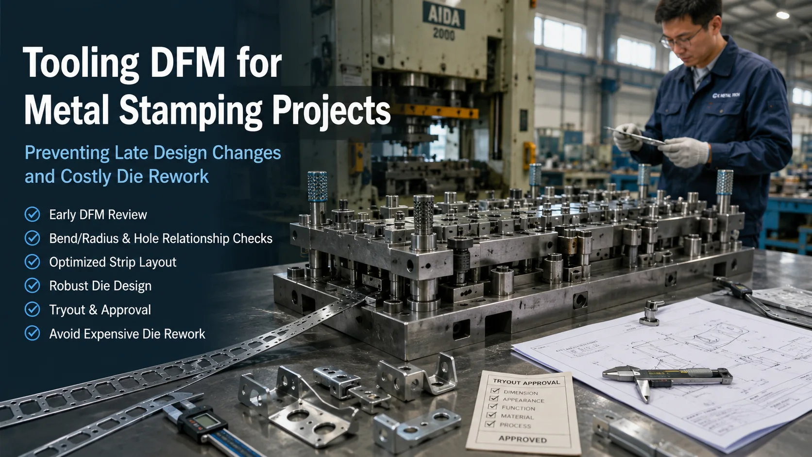
Antes de aprobar Servicios de estampado y utillaje de metales de precisiónSolicitar una revisión de la viabilidad de fabricación que abarque el material, el espesor, la factibilidad del conformado, las dimensiones críticas, las operaciones secundarias, la cantidad durante la vida útil y el estado de la revisión. No existe un umbral de producción universal que demuestre que el estampado será rentable.

Utilice un proceso híbrido cuando solo se necesite mecanizar características críticas.

Los procesos no siempre son opciones contrapuestas. Una pieza estampada puede crear el perfil exterior, las curvas y las características conformadas, mientras que el roscado, el escariado, el rectificado o el fresado completan una interfaz crítica.

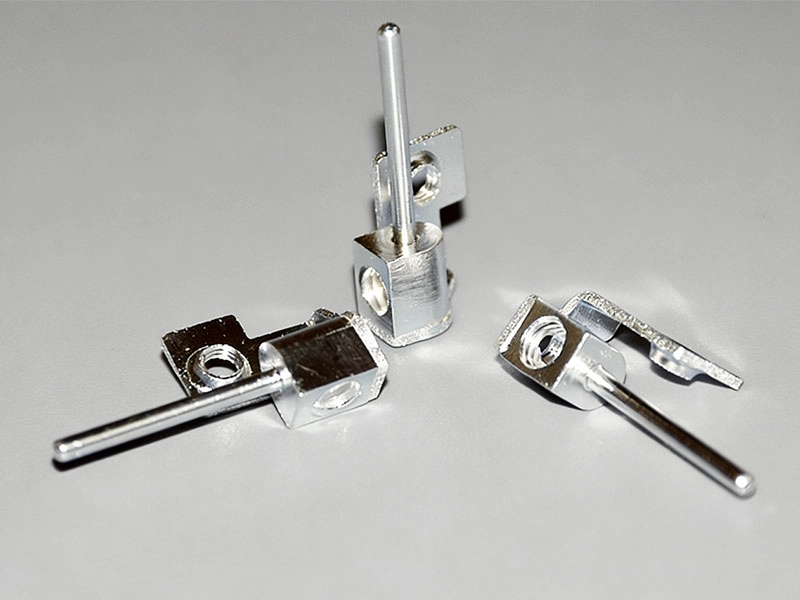
La ruta funciona mejor cuando la pieza estampada proporciona referencias de posicionamiento repetibles y el ciclo secundario es corto. Es menos atractiva cuando la distorsión del conformado hace que la fijación sea inestable o la mayoría de las características aún requieren mecanizado. Bloque de terminales de PCB estampado con mecanizado secundario Esto demuestra el principio: su ruta publicada combina estampado de precisión, doblado, roscado, perforación y galvanoplastia.


Bloque de terminales para PCB fabricado mediante procesos de estampado, doblado, roscado, perforación y mecanizado secundario de precisión.

Por qué las herramientas de estampado no siempre resultan rentables

Considerar la demanda a lo largo del tiempo, los cambios y las operaciones ocultas.

Un ciclo de vida corto del producto, las revisiones frecuentes por parte de los clientes o una demanda incierta pueden no consumir suficientes piezas para recuperar la inversión en el troquel. Modele las cantidades de producción mínimas, esperadas y máximas durante la vida útil del producto, en lugar de basarse en una única previsión anual optimista.

El costo final de la pieza estampada debe incluir desbarbado, roscado, mecanizado, limpieza, galvanizado, recubrimiento, inspección, ensamblaje, embalaje, mantenimiento de herramientas y posibles modificaciones. El presupuesto debe indicar si se incluyen pruebas, inspección de muestras, rondas de revisión, afilado, repuestos, almacenamiento y mantenimiento. Los cambios posteriores al inicio de la fabricación del troquel pueden aumentar el costo y causar retrasos, por lo que la aprobación formal de las herramientas es un control esencial.

Cómo calcular el punto de equilibrio de las herramientas de estampado

Compare dos rutas de fabricación completamente definidas:

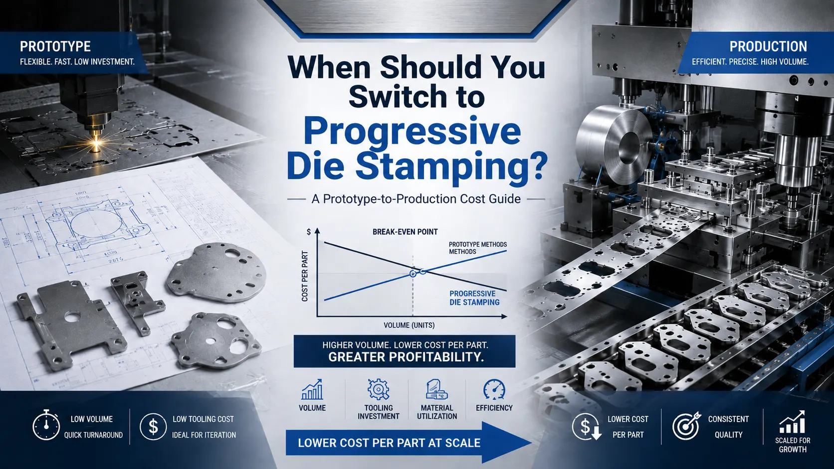
Cantidad de equilibrio = inversión en herramientas ÷ (coste unitario de la máquina CNC terminada − coste unitario de la máquina de estampado terminada)

Lo que importa es que el trabajo esté terminado. El costo del mecanizado CNC debe incluir material, configuración, mecanizado, herramientas, inspección, acabado y embalaje. El costo del estampado debe incluir diseño de troqueles, pruebas, producción de prensas, utilización de materiales, mantenimiento, operaciones secundarias, inspección, acabado y embalaje.

Si una pieza estampada aún necesita mecanizado CNC para perforaciones y roscas, utilice el costo de la pieza híbrida terminada, no el precio de la prensa sola. Pruebe con diferentes volúmenes. Una pequeña diferencia en el costo unitario genera un período de recuperación de la inversión prolongado; una diferencia mayor podría justificar la inversión en herramientas antes.

Solicite a cada licitador que cotice la misma revisión de planos, material, rangos de cantidad, alcance de la inspección, acabado, embalaje y condiciones de propiedad de las herramientas. De lo contrario, las cotizaciones podrían abarcar trabajos diferentes. La respuesta correcta a la pregunta "¿Qué volumen de producción justifica el uso de herramientas de estampado?" es un rango de punto de equilibrio específico para cada proyecto, no una cifra estándar para toda la industria.

¿La pieza mecanizada por CNC es apta para el estampado de metales?

Primero, determine si la geometría se puede producir a partir de una lámina o una bobina. El estampado corta y da forma a piezas planas, mientras que el mecanizado elimina material de una pieza sólida. Las secciones gruesas, las características cerradas o las geometrías complejas de múltiples planos pueden no ser directamente reproducibles.

Separe las características estampables de las características mecanizadas críticas.

Comience con la forma estándar. ¿Podría la función utilizar un espesor de lámina uniforme? Revise los pliegues, la profundidad de embutición, la relación entre el orificio y el borde, la recuperación elástica y las superficies propensas a las rebabas.

Clasifique las características del dibujo en tres grupos: aptas para estampado, posibles tras un cambio de diseño o tolerancia, y que aún requieren mecanizado. Los orificios de precisión, las roscas profundas, las superficies de sellado, las ubicaciones de los cojinetes y las superficies de referencia pueden seguir siendo operaciones secundarias. Confirme las referencias de ubicación, el margen de mecanizado y cómo la variación del conformado afectará la configuración final. El mecanizado CNC secundario se utiliza habitualmente para orificios de alta precisión y superficies de montaje en componentes estampados.

Cómo pasar de un prototipo CNC a la producción estampada

Un prototipo CNC valida la funcionalidad, pero no necesariamente la capacidad de estampado. Su dibujo puede contener esquinas afiladas, espesor variable o tolerancias estrictas creadas en función del mecanizado en lugar del conformado.

Congelar los requisitos y luego usar DFM y la aprobación del primer artículo.

Antes de la fabricación definitiva, confirme el material, el espesor, las interfaces, las dimensiones críticas, el acabado y la revisión de los planos. Los proyectos que aún estén experimentando cambios funcionales o en la interfaz con el cliente deben mantenerse en un proceso flexible hasta que se resuelvan los riesgos principales.

Una transición controlada sigue esta secuencia: validación del prototipo, diseño para la fabricación (DFM) del estampado, revisión del plano de producción, diseño de la herramienta, prueba de la herramienta, inspección de la muestra, corrección, aprobación del primer artículo, prueba piloto y liberación de la producción. La revisión de la muestra debe incluir rebabas, grietas, arrugas, recuperación elástica, estado del recubrimiento, apariencia y rendimiento del ensamblaje, no solo las dimensiones.

Qué deben incluir los compradores en una solicitud de cotización de CNC a estampado

Para obtener un presupuesto preciso se requiere el dibujo 2D actual y el archivo STEP, el material y la forma del material base, el espesor, las cantidades anuales y de por vida, el proceso actual, las tolerancias críticas, el acabado, el mecanizado secundario, la inspección, el embalaje y los cambios conocidos.

Compare también la propiedad de las herramientas, su almacenamiento, mantenimiento, afilado, repuestos, costos de modificación, derechos de transferencia y manejo al final del programa. Un precio bajo del troquel puede generar costos adicionales si se excluyen los cambios de ingeniería o el soporte de producción.

Cómo elegir un proveedor para la transición de CNC a estampado

Un proveedor cualificado debe evaluar ambas opciones. Debe verificar si las herramientas se fabrican internamente, si los equipos de prueba y producción comparten responsabilidades, si se puede coordinar el trabajo secundario y cómo se controlan las primeras muestras, las revisiones, el desgaste de las herramientas y las acciones correctivas.

Zhejiang Chuangkai Mechanical and Electrical Technology Co., Ltd., también conocida como CK Metal Tech, combina herramientas, estampado de metales, mecanizado CNC, tratamiento de superficies, inspección y ensamblaje dentro de su fabricación integrada de metales de precisión Alcance. Sus recursos confirmados incluyen 8 máquinas CNC de cuatro ejes, 18 tornos CNC de precisión y capacidad de mecanizado tipo suizo. CK Metal Tech también fabrica herramientas progresivas, de embutición y compuestas, y cuenta con la certificación IATF 16949. Esto respalda las revisiones de rutas CNC completas, de estampado completo e híbridas.

Conclusión

El utillaje de estampado resulta rentable cuando la pieza es realmente apta para el estampado, el diseño es estable y el ahorro a lo largo de su vida útil supera los costes de utillaje, mantenimiento, validación, procesamiento secundario y riesgo de revisión. El mecanizado CNC sigue siendo útil para prototipos, cambios de diseño, geometrías sólidas y características de precisión. Un proceso híbrido puede ser la opción más equilibrada cuando la forma base se puede estampar, pero las interfaces funcionales aún requieren mecanizado.

Para una revisión del proyecto, prepare el último dibujo, archivo STEP, material, cantidad objetivo, vida útil del programa, dimensiones críticas, operaciones secundarias y requisitos de calidad. Estos detalles permiten a CK Metal Tech Solicitar una revisión DFM de CNC a estampado y comparar rutas viables sin necesidad de invertir en herramientas de inmediato.

Preguntas frecuentes

¿Qué volumen de producción hace que el estampado de metales sea más barato que el mecanizado CNC?

No existe una cantidad universal. Calcule el punto de equilibrio a partir de la inversión real en herramientas y la diferencia entre los costos unitarios de mecanizado CNC y estampado, incluyendo mantenimiento, trabajos secundarios, acabado, inspección y riesgo de cambios de diseño.

¿Es posible convertir una pieza mecanizada por CNC directamente en una pieza estampada de metal?

En ocasiones, pero generalmente no sin un análisis DFM (Diseño para la Fabricación). Las secciones sólidas, el espesor variable, las características profundas o las tolerancias estrictas pueden requerir un rediseño antes de que comience la fabricación de las herramientas.

¿Las piezas estampadas aún requieren mecanizado CNC?

Es posible. Las roscas, los orificios de precisión, los ajustes de cojinetes, las superficies de sellado, las superficies de referencia o las características de montaje ajustadas pueden requerir mecanizado secundario, taladrado, roscado, escariado o rectificado.

¿Cómo puede un comprador saber si la inversión en herramientas de estampado resultará rentable?

Confirme la viabilidad del estampado y, a continuación, compare los costes del ciclo de vida completo en escenarios de baja, media y alta demanda. La comparación resulta más sólida cuando el diseño está definido y se incluyen las operaciones ocultas en ambas cotizaciones.

¿Qué aspectos se deben tener en cuenta al elegir un fabricante de herramientas de estampado?

Verifique el diseño interno de herramientas, el soporte DFM, las pruebas, los procedimientos de primera muestra, el control de revisiones, el mecanizado secundario, la inspección, el mantenimiento de herramientas, los términos de propiedad y la gestión de la calidad de la producción.

30th julio 2026
Hogar
WhatsApp
Correo electrónico
Contactos