CHUANGKAI

a i l a n d

Loading

     
home // blog

blog

Sheet Metal Design for AI Server Racks and Data Center Cabinets: Strength, Airflow, Cooling Integration and RFQ Checklist


Sheet Metal Design for AI Server Racks and Data Center Cabinets Strength, Airflow, Cooling Integration and RFQ Checklist

AI server rack design must connect structural strength, airflow, cooling hardware, service access, and sheet metal manufacturability before drawings are released for quotation. A cabinet may fit every listed component yet still fail if rails deflect, exhaust air recirculates, cables block the rear path, or a late-added coolant manifold interferes with removable panels. The practical goal is to convert equipment loads and cooling architecture into a buildable data center cabinet design, a testable prototype, and an RFQ that different suppliers can quote on the same basis.

Define the Rack, Cabinet, and Cooling Scope Before Designing the Sheet Metal Structure

Distinguish AI Server Racks, Data Center Cabinets, and Aisle Containment

An open rack mainly supports equipment, rails, power distribution, and cables. A cabinet adds doors, side panels, top panels, access control, and a more controlled internal air path. Aisle containment is a room-level airflow system and should not be confused with the cabinet.

Buyers should identify responsibility for rails, filters, blanking panels, PDU brackets, cable accessories, grounding hardware, and final assembly. A rack fabricator may not cover containment panels, facility ducting, or coolant distribution equipment. Without a clear boundary, suppliers may quote different products under the same description.

Translate Air-Cooled, Liquid-Ready, and Hybrid Cooling into Mechanical Requirements

An air-cooled rack needs an unobstructed inlet and exhaust route. A liquid-ready design may also require manifold brackets, hose routing, quick-connect access, drip-management provisions, and service clearance. A hybrid rack must accommodate both liquid hardware and residual air-cooled loads.

ASHRAE recommends matching cooling architecture and airflow management to AI rack density and treating power and cooling as connected design decisions. Before freezing the sheet metal geometry, confirm the cooling method, component envelopes, service direction, and responsibility for thermal validation.

Design the Structure Around the Actual Load Path

Define Static Load, Center of Gravity, Anchoring, and Transport Conditions

Total equipment weight is only the starting point. Door-mounted hardware, PDUs, cables, manifolds, rear cooling assemblies, and extended service trays can change local loading and stability. State whether the cabinet will remain fixed, move on casters, be anchored, or ship with equipment installed.

The RFQ should identify installation orientation, lifting points, floor interfaces, service extension conditions, and transport expectations. A structure suitable for stationary use may not be suitable for loaded shipment. Missing these inputs prevents a defensible decision about reinforcement, base geometry, or connection design.

Select Material, Sheet Thickness, Stiffeners, and Joint Types

Increasing sheet thickness is not the only way to raise stiffness. Folded edges, return flanges, formed ribs, localized supports, closed sections, and shorter unsupported spans may control deflection with less added mass. The right route depends on cabinet size, openings, load location, production volume, and shipping method.

Structural Route Suitable Use Main Purchasing Checks
Welded frame Fixed installation requiring rigidity Distortion, datum control, finish access
Bolted frame Modular design or shipment in sections Joint security, alignment, repeat assembly
Hybrid structure Rigid load path with removable modules Tolerance stack-up and interface control

Any thickness or reinforcement proposal should be checked against the actual load case rather than copied from a standard enclosure.

Create a Controlled Airflow Path Through the Cabinet

Design the Front-to-Rear Air Path, Doors, and Leakage Control

For front-to-rear-cooled equipment, the intake area should align with server inlets and the rear zone should remain clear. Perforated doors must balance open area with stiffness, hinge loading, security, and filtration. A universal perforation percentage is unsuitable because pressure drop depends on pattern, occupied area, equipment fans, and system configuration.

Unused rack positions and panel gaps can create bypass airflow. Define blanking requirements, door seals, side clearances, and filter arrangements. Assess the prototype as an assembled cabinet with representative doors, rails, and components, not as isolated sheet metal parts.

Prevent Recirculation, Cable Blockage, and Top-of-Rack Hot Spots

Hot exhaust can return through open rack spaces, gaps around doors, top openings, or congested rear zones. Cable bundles, PDUs, crossmembers, and cooling hoses may also restrict exhaust flow.

Blanking panels, baffles, disciplined cable routes, and clear exhaust zones can reduce cabinet-level recirculation, but they cannot correct an unsuitable room layout.


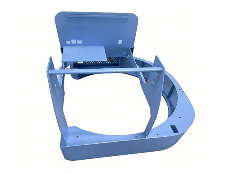
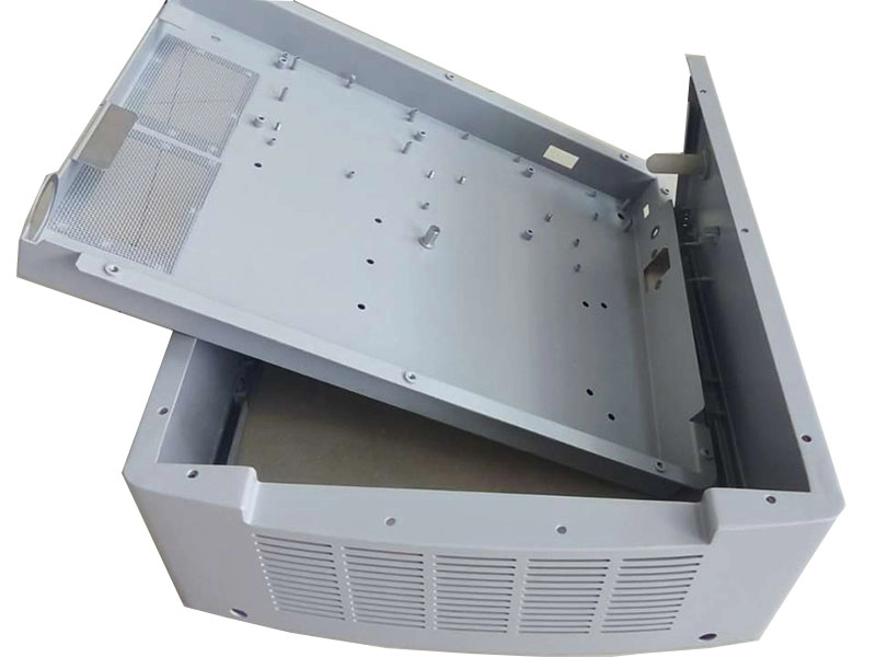
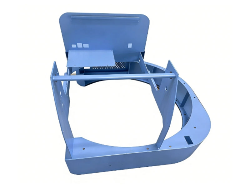
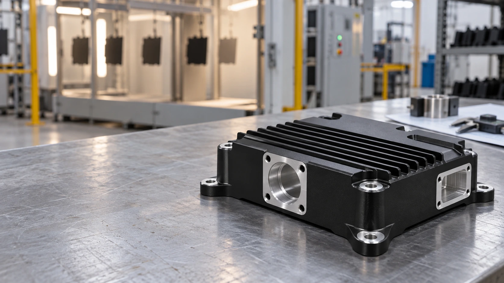
Medical and industrial equipment chassis assembly with cooling grilles and internal mounting rails

An industrial equipment chassis with cooling grilles and internal mounting rails shows how ventilation features, filters, supports, modular access, and assembly must be planned together. The referenced CK Metal Tech product serves medical, industrial testing, and communication applications, so it is a structural example rather than an AI rack performance claim.

Prepare the Cabinet for Cooling Components and Service Access

Plan Interfaces for Manifolds, Hoses, Fans, and Rear-Door Systems

A liquid-ready rack may need adjustable manifold brackets, controlled hose bend space, protected quick-connect locations, and separation between coolant paths and sensitive electrical areas. A rear-door heat exchanger or fan-assisted door may add weight to the hinge side and change rear service clearance.

Include component interface drawings, estimated weight, connection direction, removal path, and responsibility for brackets or purchased hardware. Adjustable interfaces may suit an evolving cooling system, but excessive adjustability can reduce stiffness and complicate repeat assembly.

Design Removable Panels for Maintenance, Inspection, and Replacement

Doors and panels should provide access without forcing technicians to disconnect unrelated cables or coolant lines. Review tool clearance, lifting method, panel weight, fastener retention, grounding continuity, and the sequence for removing a manifold, PDU, fan unit, or server.

More removable panels are not automatically better. Each joint can introduce alignment variation, leakage paths, and grounding requirements. Use removable construction where it supports real maintenance tasks and fixed structure where rigidity matters more.

Apply Sheet Metal DFM and Validate the Prototype

Control Bending, Welding, Fasteners, Tolerances, and Grounding Surfaces

Bend variation, weld shrinkage, hardware position, panel flatness, and coating buildup can combine into door, rail, or equipment-alignment problems. Drawings should identify functional datums, assembly-sensitive interfaces, grounding surfaces, masked threads, and dimensions that apply after finishing.

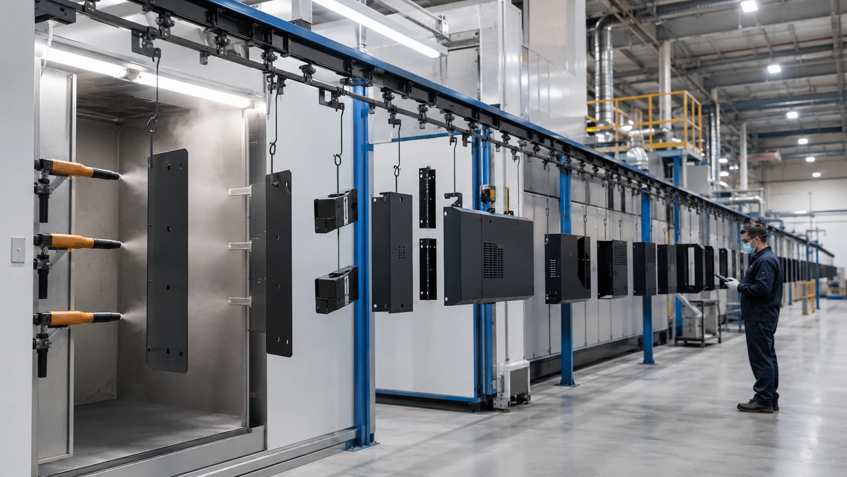
CK Metal Tech’s precision sheet metal manufacturing capabilities include CNC laser cutting, punching, bending, riveting, welding, grinding, and processing of several industrial sheet materials. Suitability depends on the drawing, dimensions, material, quantity, and inspection requirements. Buyers can also review powder coating vs wet painting for sheet metal parts when defining cosmetic areas, masking, grounding points, corrosion expectations, and assembly interfaces.

Validate Structure, Fit, Airflow, and Transport Before Repeat Production

Prototype approval should cover more than individual dimensions. A representative build may need rail alignment, door operation, panel fit, grounding continuity, equipment installation, cable routing, cooling-component clearance, and packaging review. Structural, airflow, and thermal testing responsibilities must be agreed before the order because a fabrication supplier may build to validated drawings without providing facility-level thermal engineering.

Before repeat production, freeze approved revisions, fixtures, inspection points, purchased components, packaging, and change-control rules. A successful hand-built sample does not prove repeatability without a defined production process.

Prepare the RFQ and Qualify a Sheet Metal Rack Manufacturer

Include the Technical Inputs Needed for a Comparable Quote

A custom server rack RFQ should include:

  • Controlled 2D drawings, 3D models, BOM, and revision status
  • Dimensions, equipment layout, rail interfaces, and component weights
  • Static, service, anchoring, lifting, and transport conditions
  • Air, liquid-ready, or hybrid cooling architecture
  • Door, cable, PDU, fan, filter, and manifold requirements
  • Material, finish, grounding, masking, and cosmetic specifications
  • Prototype quantity, production volume, inspection, assembly, and packaging scope

When the design is not frozen, request a DFM and prototype quotation rather than a production price based on unresolved assumptions.

Evaluate Supplier Capabilities, Evidence, and Red Flags

A qualified data center cabinet manufacturer should explain how cutting, bending, joining, finishing, inspection, trial assembly, and packaging remain controlled. Ask how functional datums are maintained, how cabinet-level fit is checked, which processes are subcontracted, and how revisions reach production.

Red flags include quotations without a revision, vague load assumptions, no review of cooling hardware, and no cabinet-level assembly check. Zhejiang Chuangkai Mechanical and Electrical Technology Co., Ltd., operating as CK Metal Tech, combines sheet metal processing, machining, stamping, surface finishing, and assembly through its integrated precision metal manufacturing capabilities. Each AI server rack or data center cabinet still requires project-specific review.

Conclusion

A reliable AI server rack begins with a defined load path, controlled airflow, confirmed cooling interfaces, service access, and a manufacturing plan that accounts for bending, welding, hardware, finishing, and assembly. Generic sheet thickness, perforation percentages, or “liquid-ready” labels cannot replace application-specific review.

Buyers can submit drawings for a custom server cabinet manufacturing review with the 2D drawings, 3D model, BOM, dimensions, material, equipment weight, cooling configuration, target quantity, inspection scope, and packaging requirements. CK Metal Tech can then assess the requested route against its available fabrication and assembly processes.

Frequently Asked Questions

How do I select sheet metal thickness for an AI server rack?

Thickness depends on the load path, unsupported span, openings, formed geometry, joint type, equipment weight, service conditions, and transport method. Review local deflection and interface stability rather than selecting thickness from total weight alone.

Does every AI server rack need liquid cooling?

No. The suitable architecture depends on heat output, rack density, facility conditions, server design, and operating plan. Air-cooled, liquid-ready, and hybrid configurations require different mechanical interfaces.

How can a server cabinet reduce hot-air recirculation?

Align intake and exhaust openings with the equipment, close unused rack spaces, reduce bypass gaps, keep cables and accessories out of the exhaust path, and coordinate the cabinet with aisle-level air management.

What information is needed for a custom server rack quote?

Provide drawings, BOM, dimensions, equipment layout and weight, cooling architecture, rail and accessory interfaces, material, finish, grounding, masking, quantities, inspection, assembly, and packaging requirements.

How do I choose a data center cabinet manufacturer?

Evaluate the manufacturing route, datum control, joining methods, finishing, cabinet-level assembly, inspection evidence, revision control, subcontractor management, prototype-to-production planning, and technical communication.

14th August 2026

How to Source Semiconductor Equipment Frames and Enclosures: Supplier Qualification and RFQ Checklist


How to Source Semiconductor Equipment Frames and Enclosures Supplier Qualification and RFQ Checklist

Choosing a semiconductor equipment frame supplier requires more than comparing prices. A frame or enclosure may meet individual dimensions yet still create problems when doors, rails, panels, and internal modules are assembled. Buyers must connect design intent, manufacturing route, inspection, revision control, and capacity. This guide explains how to prepare a quote-ready RFQ, qualify a semiconductor equipment enclosure manufacturer, reduce dimensional and finishing risks, and select a supplier for prototype, NPI, or repeat production.

Define the Frame and Enclosure Scope Before Sending an RFQ

Distinguish Frames, Enclosures, Chassis, and Process Chambers

A welded frame normally carries loads and establishes equipment geometry. A sheet metal enclosure protects internal components and may include doors, removable panels, ventilation features, mounting rails, cable openings, and grounding points.

Process chambers are different because vacuum, process gases, controlled atmospheres, or special cleanliness requirements may demand capabilities beyond structural fabrication. The RFQ should separate manufactured parts, purchased components, customer-supplied items, and final assembly duties, including panel fitting, hardware installation, functional checks, and module-level packaging.

This distinction prevents a common sourcing error: selecting a capable general fabricator for a component that requires application-specific sealing, cleanliness, or validation. It also prevents missing costs when a quoted frame excludes the panels, hardware, purchased items, or assembly work needed to make it usable.

Identify Functional Datums, Interfaces, Loads, and Conditions

“High precision” is not a usable purchasing specification. Engineering teams should identify the surfaces, holes, rails, and interfaces that control installation or performance. These may include base mounting points, module interfaces, door openings, grounding surfaces, and alignment features.

The suitable structure depends on size, load, stiffness, weight, corrosion exposure, service access, and finishing requirements. Welded steel, formed sheet metal, aluminum structures, machined bases, and cast iron assemblies suit different conditions. A wafer dicing equipment cast iron frame assembly, for example, should be reviewed as a combined route involving structure, machined interfaces, inspection, and assembly rather than as a generic metal part.


Wafer dicing equipment cast iron frame assembly for semiconductor equipment

Before requesting quotations, buyers should confirm which features are functional datums, which surfaces contact other modules, and whether the supplier must verify the completed assembly rather than individual components.

Build a Quote-Ready Semiconductor Equipment Enclosure RFQ

Provide Controlled Drawings, Models, BOMs, and Revisions

A useful semiconductor equipment enclosure RFQ should include current 2D drawings, 3D models when available, a BOM, revision status, material requirements, and expected quantities. The 2D drawing should control tolerances, datums, finishes, inspection notes, and special requirements.

Identify the controlling file and require the quotation to state the reviewed revision. Customer-supplied parts, standard hardware, and supplier-purchased items must be marked clearly. Otherwise, two suppliers may appear to quote the same assembly while including different materials, fasteners, finishing operations, or inspection work.

When a design is still changing, request a DFM review and prototype quotation before asking for a firm production price. This allows the supplier to identify inaccessible welds, difficult bend sequences, coating conflicts, uncertain datums, and features that may require machining after fabrication.

Specify CTQs, Finish, Inspection, Volumes, and Packaging

Critical-to-quality characteristics should relate to function. Tightening every dimension may raise cost without improving assembly, while leaving mounting interfaces undefined can make a compliant frame unusable.

State prototype quantity, batch size, annual demand, material, surface finish, cosmetic zones, masking areas, grounding points, inspection records, labeling, and packaging. The supplier should know whether dimensions apply before or after coating and which threads, electrical contact areas, locating surfaces, or slots must remain free of buildup.

Packaging also belongs in the RFQ. Large frames may require defined lifting and restraint, while finished panels need protection against rubbing, edge impact, moisture, or mixed-part contact. These details help suppliers quote comparable scopes instead of hiding different assumptions behind different unit prices.

Evaluate the Supplier’s Complete Manufacturing Route

Review Structural Fabrication and Machined Interfaces

A semiconductor equipment frame manufacturer should explain the route from raw material to approved assembly. For a welded structure, that may include cutting, fixture setup, welding sequence, intermediate checks, correction, post-weld machining where needed, surface finishing, dimensional inspection, and trial assembly.

Ask how datums are established before welding, protected during fabrication, and verified afterward. Post-weld machining may be appropriate when welding cannot reliably hold a mounting surface or hole pattern, but it is not required for every design. The decision depends on structure, tolerance, access, and risk.

Critical outsourced operations should also be disclosed. Outsourcing is not automatically unsuitable, but the main supplier should explain specification control, batch identification, incoming verification, and responsibility for nonconforming work. The quotation should cover the completed manufacturing route rather than only the processes performed in-house.

Verify Enclosure Fabrication, Finishing, and Assembly

For equipment housings, check whether the supplier can connect cutting, bending, hardware insertion, welding, grinding, finishing, and assembly. CK Metal Tech’s precision sheet metal manufacturing capabilities include laser cutting, CNC punching, bending, riveting, welding, grinding, and processing of several commonly used industrial sheet materials. Suitability still depends on the drawing, material, size, finish, and inspection plan.

Buyers should confirm when doors, panels, hinges, rails, fasteners, and internal mounting features will be trial-fitted. Features affected by coating should be reviewed before finishing. Shipping separate parts without checking the assembled condition may transfer tolerance and fit problems to the equipment builder.

Where possible, prototype approval should include representative internal components or checking fixtures. This reveals whether the enclosure functions as an assembly, not merely whether each component passes an isolated measurement.

Prevent Distortion, Misalignment, and Assembly Failures

Control Weld Distortion and Protect Functional Datums

Welding creates local heating and uneven contraction. Joint layout, material thickness, restraint, and sequence can cause twisting, bowing, or movement at mounting interfaces.

Buyers should ask how fixtures locate the structure, how the welding sequence balances heat input, and which dimensions are checked before and after finishing. First-article inspection should prioritize mounting planes, hole patterns, diagonals, rail interfaces, and features that connect to other modules.

If final correction is the main control method, ask how it affects repeatability and whether the fixture, sequence, joint design, or machining plan needs revision. Correction may produce an acceptable prototype without proving that the same route will remain stable across repeat batches.

A suitable supplier should be able to connect the drawing’s functional requirements with a practical fabrication and measurement plan.

Prevent Tolerance Stack-Up and Coating Interference

Assembly problems often result from several small deviations rather than one defective part. Bend location, bend angle, welded position, inserted hardware, hole size, and coating buildup can accumulate across an enclosure.

Doors may rub, rails may shift, modules may not align, or grounding points may become insulated. Drawings should distinguish finished dimensions from pre-coating dimensions and identify masked areas, threaded holes, contact surfaces, and assembly-sensitive slots.

Prototype approval should include fitting of doors, panels, hardware, and representative internal components where practical. For repeated interfaces, review tolerance accumulation instead of tightening every feature. Adjustment slots, locating tabs, machined references, or controlled assembly points may provide a more stable solution than imposing excessive tolerances on all sheet metal dimensions.

Verify Inspection, Traceability, and Engineering Changes

Define Evidence and Control Nonconformance

Inspection requirements should match risk. A first article may include a dimensional report, material records, finish verification, photographs, or CMM data for selected features. The RFQ should identify full-report, sampling, and functional-check requirements.

For large structures that cannot be measured in one setup, review the proposed method before production. The supplier should explain how separate measurements maintain a reliable relationship to the defined datums.

Supplier qualification should also confirm how obsolete drawings are removed, batches are identified, and deviations, substitutions, rework, or repairs receive approval. Engineering changes may affect finished inventory, work in process, purchased components, fixtures, inspection programs, and packaging documents.

SEMI describes standards as technical agreements used in purchase specifications and equipment evaluations, while traceability is an established SEMI standards subject. This supports defining project-specific documentation rather than assuming that the word “semiconductor” creates one universal inspection package.

Compare Suppliers Before Awarding the Order

A supplier that produces one acceptable prototype may not be ready for repeat production. NPI needs engineering communication and flexible planning; repeat production adds fixture control, stable inspection, capacity planning, subcontractor control, and disciplined change management. Compare the complete route, not only unit price.

Qualification Area What the Buyer Should Confirm
Application fit Similar size, material, processes, and assembly risk
Manufacturing route Clear sequence through fabrication, finishing, inspection, and packaging
Datum control Method for protecting and measuring functional interfaces
Quality evidence Appropriate first-article, material, finish, and inspection records
Change control Revision, deviation, rework, and obsolete-inventory procedures
Capacity Fit for prototype, pilot batch, and expected repeat demand
Communication Technical contact and documented review of assumptions

Red flags include vague answers about datums, excluded critical processes, uncontrolled subcontracting, missing revision references, and no trial-assembly plan. Depending on project risk, the next step may be a technical review, supplier audit, first article, pilot batch, or production approval.

How CK Metal Tech Supports Frame and Enclosure Projects

Zhejiang Chuangkai Mechanical and Electrical Technology Co., Ltd., operating as CK Metal Tech, combines precision sheet metal processing, machining, metal stamping, surface treatment, and component assembly. Its integrated precision metal manufacturing capabilities can support build-to-print projects requiring connected fabrication steps, and the company website lists a wafer dicing equipment cast iron frame assembly among its products.

This capability range does not replace project qualification. Buyers should submit drawings, material, functional datums, finish, target quantity, inspection requirements, and operating conditions so CK Metal Tech can review whether the requested route fits the available processes and identify points requiring clarification.

Conclusion

Successful semiconductor equipment frame sourcing starts with a controlled specification, not a supplier shortlist. Define the assembly boundary, functional datums, manufacturing route, finish, inspection evidence, change control, production stage, and packaging before comparing prices. A qualified supplier should explain how those requirements remain connected from first article through repeat production.

For a project-specific review, buyers can submit drawings and RFQ requirements to CK Metal Tech with the 2D drawing, 3D model, BOM, material, quantity, application, critical interfaces, finish, and inspection expectations. Samples or failure photographs can help focus the review.

FAQs

What files are needed to quote a semiconductor equipment frame?

Provide current 2D drawings, a 3D model when available, BOM, revision, material, finish, quantities, critical datums, inspection requirements, packaging, and delivery location. Identify the controlling document and explain unresolved assumptions.

Does every semiconductor equipment enclosure require cleanroom assembly?

No. It depends on installation location, exposure to sensitive processes, customer specifications, particle risk, and downstream assembly. Cleanliness, ESD controls, packaging, and permitted residues should be stated explicitly.

What tolerances should be specified for a welded equipment frame?

Focus on mounting planes, module interfaces, hole patterns, rails, and other functional datums. Wider limits may suit nonfunctional dimensions. The supplier should review whether welding, correction, or post-weld machining can hold each requirement.

When should a welded frame be machined after welding?

Post-weld machining may be suitable when critical mounting surfaces or hole locations cannot be held consistently through fabrication and correction alone. The decision depends on frame size, stiffness, access, tolerance, material, and measurement method.

How should buyers compare semiconductor equipment enclosure suppliers?

Compare drawing review, fabrication route, datum control, finishing, trial assembly, inspection records, revision control, capacity, subcontractors, packaging, and technical communication. Confirm essential operations and documents are included.

13th August 2026

How to Control Runout in Long Shaft Machining: Setup, Grinding, and Inspection for Parts Up to 4 Meters


How to Control Runout in Long Shaft Machining Setup, Grinding, and Inspection for Parts Up to 4 Meters

Long shaft machining becomes difficult when a part passes diameter inspection but still shows excessive runout, bow, taper, vibration, or assembly misalignment. The cause may begin in the raw material, appear during stock removal, develop after heat treatment, or result from an inspection setup that does not reproduce the drawing datum. For shafts approaching four meters, material condition, workholding, machining sequence, grinding, inspection, and packaging must form one controlled process.

Long Shaft Machining Runout: Diagnose the Pattern First

Runout is commonly checked by rotating the shaft through 360 degrees and comparing the indicator’s maximum and minimum readings at a specified position. The result is meaningful only when the datum, support method, gauge position, and permitted value are defined.

Observed condition Check first Next action
Runout is concentrated near one end Center holes, chucking, tailstock, datum transfer Verify the setup axis
Maximum bow appears near the middle Support spacing, stock straightness, cutting force Review support and roughing
Diameter changes along the shaft Tailstock alignment, tool wear, thermal drift Separate geometric and thermal error
Runout increases after heat treatment Residual stress, support, remaining allowance Recheck straightness before finishing
Inspection reports disagree Datum, support points, orientation, gauge position Agree on one method

This identifies whether the next review should focus on material, setup, grinding, or measurement.

Why Long Shafts Develop Runout, Taper, and Straightness Errors

Material Straightness, Residual Stress, and Heat-Treatment Distortion

A long bar may contain initial bow or uneven residual stress. Heavy material removal can release that stress and move a shaft that appeared straight during roughing. Thin sections, keyways, and large diameter changes increase the risk.

For parts requiring substantial stock removal or heat treatment, a staged route may be safer than machining directly to final size. Rough turning establishes the geometry, followed by a stability or heat-treatment step when specified, another straightness check, and finish machining. Remaining allowance should be distributed so final turning or grinding does not need to correct most of the error from one side.

The RFQ should identify material grade, supply condition, heat treatment, hardness, and incoming straightness requirements.

Cutting Force, Unsupported Length, Clamping, and Heat

A slender shaft deflects under radial cutting force. As unsupported length increases, the tool may push the workpiece away, causing taper, barrel shape, chatter, or inconsistent diameter. Excessive chuck, tailstock, or steady-rest pressure can also bend the shaft before cutting.

Lower cutting force, short tool overhang, staged passes, controlled support, and temperature management reduce risk. A strategy that works on a rigid section may fail at the smallest diameter. Buyers should ask how the supplier will support that section, manage tool wear and thermal growth, and perform in-process checks.

Choosing the Right Setup for Long Shaft Turning

The setup should reflect shaft length, diameter, weight, material, critical datums, and permitted runout. Buyers can review CK Metal Tech’s long shaft CNC machining and grinding capabilities before submitting a drawing.

Between-Centers Turning and Tailstock Alignment

Turning between centers can preserve one rotational axis through several operations when center holes remain available as process datums. It is useful when multiple journals must relate to the same axis, although end geometry, weight, or feature access may require another setup.

Center holes must be prepared and protected because inconsistent seating transfers into runout. Tailstock alignment and thrust also matter: insufficient support permits movement, while excessive force may bow a slender shaft. The supplier should check initial indicator readings, explain how the part will be reloaded, and confirm whether center holes are temporary process features or drawing-controlled features.

Steady Rest vs. Follow Rest

A steady rest supports the shaft at a fixed position; a follow rest moves with the cutting tool. The correct choice depends on where the unsupported span develops.

Official machine guidance describes steady rests as support for long or narrow shafts and instructs operators to adjust rollers without causing workpiece deflection. It also recommends rotating the part and checking it with an indicator after adjustment.

Rollers that are too loose provide little control; rollers that are too tight can create friction, marks, heat, or artificial bending. The supplier should identify support locations and explain how alignment will be rechecked after repositioning.

Machining Sequence for Controlling Long-Shaft Runout

Rough Turning, Stability Review, and Finish Turning

A sound process separates heavy stock removal from final geometry control. Rough turning establishes the shape and reveals how the blank responds as material is removed. The shaft can then be checked for bow and datum movement before heat treatment, semi-finishing, or grinding.

A typical route is:

Material review → datum preparation → rough turning → stability or heat-treatment step → straightness review → semi-finishing → finish turning or grinding → final inspection.

The exact route depends on material, geometry, hardness, and drawing requirements. Repeated chucking should be minimized or controlled through consistent center holes, journals, or other process datums.

When Grinding Is Required—and When Turning Is Enough

Grinding may suit hardened journals, bearing fits, wear surfaces, or requirements involving surface condition, roundness, cylindricity, and relationships between diameters. It should not be added automatically. If finish turning meets the drawing, another setup may add cost and datum-transfer risk.


Precision shaft components manufactured with CNC turning and grinding processes for long shaft machining applications

For ground shafts, confirm the grinding datum, support method, allowance, heat-treatment sequence, and equipment range. CK Metal Tech’s precision-turned shaft components with grinding use a published route combining precision turning, grinding, and quenching for custom alloy-steel or stainless-steel designs.

This product does not establish a four-meter grinding range. Maximum length, diameter, weight, and geometry must be verified for each drawing.

How to Inspect Runout and Straightness on a Long Shaft

Define the Datum Axis Before Selecting the Gauge

Circular runout, total runout, straightness, roundness, and coaxial relationships describe different conditions. A shaft may meet diameter tolerance while failing rotational function. The drawing should identify the functional datum axis and the characteristic that affects assembly.

The datum may come from center holes, two bearing journals, or another functional feature. Measuring one section does not prove the complete shaft meets total runout or straightness requirements. Reports should state the datum, support method, gauge positions, orientation, rotation method, and result.

Control Gravity Sag and Measurement Support

A long slender shaft can sag under its own weight during horizontal inspection. Between-centers measurement, rollers, V-blocks, and coordinate measurement systems may produce different readings if support positions and datums are not correlated.

Inspection equipment must match the workpiece envelope, weight, access, and required uncertainty. A CMM may suit some features, but it should not be assumed that every machine can accommodate a complete four-meter shaft. Supplier and buyer should agree on support spacing, orientation, rotation method, and measurement correlation.

CK Metal Tech has CMM, 2.5D measurement, metallographic, and hardness-testing resources, but the method for a full-length four-meter shaft must be confirmed against the equipment range.

Troubleshooting Long-Shaft Machining Defects

Runout near one end points first to the chuck, center hole, tailstock, or datum transfer. Maximum bow near the middle suggests stock straightness, support spacing, cutting force, or stress release. Gradual taper calls for checks of alignment, tool wear, machine geometry, and temperature. Periodic chatter may indicate poor rigidity, unsuitable speed, excessive tool overhang, or unstable rest contact.

If runout increases after heat treatment, verify straightness before removing final allowance. If grinding introduces new error, review grinding heat, support pressure, wheel condition, and datum correlation. Rework should not begin until the cause and remaining allowance are understood.

RFQ Checklist for Long Shafts Up to 4 Meters

Drawing, Material, and Application Data

Provide the current 2D drawing and 3D model, total and effective machining lengths, maximum and minimum diameters, estimated weight, material grade and condition, center holes, functional datums, and all stepped, threaded, tapered, keyed, or drilled features.

State circular runout, total runout, straightness, surface requirements, heat treatment, hardness, grinding scope, and inspection records. Application details such as speed, load, mating components, and environment help identify critical features. Include quantities and any photographs or reports from an existing defect.

Capacity, Inspection, and Packaging Questions

Ask the supplier to confirm usable between-centers length, maximum diameter and weight, lifting method, tailstock and rest configuration, and which turning, heat treatment, grinding, and inspection stages are internal or outsourced. Confirm grinding range rather than assuming it matches turning capacity.

The quotation should identify datum simulation, inspection supports, sample and production setups, and packaging. A shaft that passes inspection can still bend if supported incorrectly during storage or transport.

How to Choose a Long Shaft Machining Supplier

Evaluate the Complete Manufacturing Route

A suitable supplier should explain how material review, datum preparation, roughing, support, heat treatment, finishing, grinding, inspection, and packaging connect. The review should identify where straightness is checked, how setups are repeated, which features establish the final axis, and what happens if the shaft moves after heat treatment.

Buyers should confirm whether first articles and production parts use the same route, which records are available, and how abnormal results are handled. Confirming machine length without discussing weight, support, grinding, and inspection is not a complete feasibility review.

Relevant CK Metal Tech Capabilities

Zhejiang Chuangkai Mechanical and Electrical Technology Co., Ltd. connects machining with related processes through its integrated precision metal manufacturing capabilities. Buyers can also review about Zhejiang Chuangkai Mechanical and Electrical Technology Co., Ltd. when evaluating the supplier.

Confirmed resources include 18 precision CNC lathes, turning capacity for workpieces up to approximately four meters, internal and external cylindrical grinding, centerless grinding, thread rolling, tapping, and drilling. CK Metal Tech also holds IATF 16949 certification, while its website presents machining, stamping, sheet-metal fabrication, surface treatment, and assembly as connected services.

Maximum diameter, weight, grinding length, support arrangement, and achievable runout or straightness must still be verified for each project.

Conclusion

Controlling runout in long shaft machining requires more than a long-bed lathe. Material condition, datums, support pressure, cutting force, heat treatment, grinding, inspection, and transport must form one traceable route. The objective is to meet the drawing under an agreed measurement method, not to promise “zero runout.”

For a process review, submit the drawing, material, length, diameters, estimated weight, runout and straightness requirements, heat treatment, grinding scope, quantity, application, and any defect photographs or reports. Buyers can request a long shaft machining review from CK Metal Tech.

Frequently Asked Questions

How can runout be reduced when machining a long shaft?

Check raw-material straightness, datums, chuck and tailstock alignment, support location, cutting force, tool condition, and temperature. Separate roughing from finishing when stress release is likely, then inspect with the agreed datum and support method.

When is a steady rest required for long shaft turning?

A steady rest may be needed when the unsupported span permits deflection, vibration, or unstable size. The decision depends on diameter, length, weight, material, cutting force, geometry, and tolerance.

Should a long shaft be ground after CNC turning?

Grinding is appropriate when hardness, bearing fits, wear surfaces, roundness, cylindricity, or surface requirements cannot be met reliably by turning. It may be unnecessary when finish turning satisfies the drawing.

How is total runout measured on a four-meter shaft?

Define the datum axis, support arrangement, rotation method, and measurement locations. The method must consider gravity sag, equipment range, and correlation between supplier and customer inspection.

What information is needed for a long shaft machining quote?

Provide drawings, material condition, length, diameters, weight, datums, runout and straightness tolerances, surface requirements, heat treatment, grinding, features, quantities, application, inspection records, and packaging expectations.

7th August 2026

3-Axis vs 4-Axis CNC Machining: When Does a Rotary Axis Reduce Setups and Datum Error?


3-Axis vs 4-Axis CNC Machining When Does a Rotary Axis Reduce Setups and Datum Error

Choosing between 3-axis and 4-axis CNC machining should begin with the drawing, not the machine list. A rotary axis can expose several sides of a component without manual flipping, which may reduce fixture changes, repeated probing, and datum transfer. It does not automatically make every part more accurate or less expensive. The correct route depends on feature direction, tool access, cross-face tolerances, workholding, quantity, and inspection.

3-Axis or 4-Axis CNC Machining? Quick Decision Guide

Map every machined feature by direction, then identify which features must remain related to the same functional datum.

Decision factor 3-axis machining often fits 4-axis machining often fits
Feature direction One or two accessible directions Three or more sides or radial directions
Cross-face relationships Moderate or fixture-repeatable Tight relationships around a common datum
Rotary features Limited and easy to re-fixture Radial holes, circular slots, angular patterns
Quantity Prototype, low volume, changing design Stable pilot or repeat production
Setup plan One or two direct setups Several 3-axis setups can be consolidated

The process should be reviewed against the actual part, not specified only as “4-axis required.” Buyers can examine CK Metal Tech’s precision CNC machining capabilities when a drawing needs process review.

Choose 3-Axis Machining for Accessible, Single-Direction Features

Three-axis machining remains practical for plates, brackets, flanges, and simpler housings whose critical features are accessible from the top or one additional flipped orientation. A qualified flip fixture and probing can make a second setup repeatable enough for many drawings.

It is often more economical for prototypes, low quantities, or changing designs. Buyers should still ask how many times the part will be clamped, which datum is used, and where cross-face dimensions will be inspected.

Choose 4-Axis Machining for Multi-Sided or Rotary Features

Four-axis machining becomes more relevant when holes, slots, flats, or mounting faces are distributed around a part, or when cylindrical features require controlled angular spacing. Rotating the workpiece can give the tool access to several directions while preserving one primary clamping relationship.

Autodesk identifies multi-sided, cylindrical, and wrapped geometry as common 4-axis applications and notes that less re-clamping can reduce cumulative setup error. Undercuts or compound angles may still require 5-axis machining or another process.

How Multiple Setups Create Datum Shift and Positional Error

Re-Clamping, Re-Zeroing, and Fixture Stack-Up

Every new setup introduces variables such as debris under a locator, fixture error, clamping deformation, probe variation, work offsets, and inconsistent seating. Their combined effect can appear in features produced from different setups.

A part may pass individual checks yet fail cross-face position, perpendicularity, or center distance. Multiple setups remain acceptable when tolerance and fixture repeatability support them. Clear datums, probing, and first-article checks reduce risk.

Why 4-Axis Machining Reduces—but Does Not Eliminate—Error

Keeping the part clamped while it indexes removes some manual handling and repeated zero-setting. Autodesk describes this as a reason 4-axis machining can reduce misalignment and cumulative tolerance error.

The rotary setup still has an error chain. The workpiece must match the rotation center; the fixture must resist eccentric loading; and indexing, offsets, heat, and clamping must be controlled. Autodesk support identifies an incorrect work-coordinate position relative to the rotary center as a cause of wrong 4-axis output.

Part Geometry and GD&T Requirements That Drive Axis Selection

Multi-Sided Holes, Slots, Flats, and Mounting Features

Strong 4-axis candidates often contain features on adjacent or opposite faces that share a critical relationship. Examples include mounting holes around a housing, flats indexed at specified angles, or several faces referenced to one bore.

The drawing should identify which features control assembly. Position, perpendicularity, parallelism, and profile across faces may justify one rotary setup. If these relationships are loose, a 3-axis flip fixture may be sufficient. Buyers should mark cross-face critical dimensions and ask how each will be produced and measured.

Cylindrical, Wrapped, and Repeating Angular Features

Radial holes, circumferential grooves, engraving, and angular patterns are natural rotary-axis applications. Indexed machining positions the workpiece at defined angles; wrapped or simultaneous motion may be needed for a continuous path around a cylinder.


Four-axis CNC machined motor housing with annular cooling grooves for multi-sided machining applications

A relevant example is a four-axis CNC-machined motor housing made from high-strength aluminum alloy. Its published annular cooling grooves and mounting holes illustrate why rotary access may suit cylindrical and installation features. The page does not provide setup savings or tolerance comparisons.

Indexed 3+1 vs Simultaneous 4-Axis Machining

When Indexed 4-Axis Machining Is Sufficient

In indexed, or 3+1, machining, the rotary axis moves the part to a fixed angle and stops. Standard 3-axis toolpaths then machine that orientation. Autodesk separates this method from continuous rotary cutting.

It suits bolt patterns, radial holes, flats, pockets, and mounting features at known angles. It is generally easier to program and inspect than simultaneous motion. A quote should state indexed positions, feature groups, support, and remaining setups.

When Simultaneous Rotary Motion Is Required

Simultaneous 4-axis machining moves the rotary axis while cutting. It may fit helical grooves, wrapped contours, or free-form cylindrical surfaces that cannot be produced efficiently by fixed indexing. Autodesk notes that these workflows require rotary-orientation control, clearance planning, and collision avoidance.

The machine configuration, CAM strategy, postprocessor, rotary direction, and collision model must agree. Not every “4-axis” machine supports the same continuous strategies. Buyers should specify the required geometry rather than demand simultaneous motion by default.

3-Axis vs 4-Axis CNC Machining Cost

Compare Completed-Part Cost, Not Machine Hourly Rate

A 4-axis machine may have a higher hourly rate, but the completed part may cost less if it replaces fixtures, setups, transfers, and intermediate inspection. A simple component may cost more because of added programming, alignment, and workholding.

A fair comparison includes programming, fixtures, setup labor, cycle time, tooling, inspection, first-article approval, and rework risk. Separate one-time charges from recurring unit costs, and require the same finished scope.

Prototype, Pilot, and Repeat Production Decisions

A prototype may be produced efficiently in two 3-axis setups while the design is changing. After interfaces and quantities stabilize, a rotary fixture may become worthwhile for pilot or repeat production. The break point depends on fixture cost, setup time, inspection effort, geometry, and lifetime quantity.

Changing the route can alter datum flow, tool marks, burr location, and measurement. If prototype and production methods differ, critical characteristics need renewed pilot-run validation.

Common 4-Axis Machining Risks and How to Prevent Them

Rotary Centerline, Workholding, and Orientation Errors

If the programmed coordinate system does not match the actual rotary centerline, features can shift as the part turns. Fixture eccentricity may create changing tool engagement, vibration, and angular error. A reversed rotary direction or incorrect zero can mirror or misplace wrapped features.

Controls include probing the centerline, checking indicator readings, simulating the machine and fixture, verifying the postprocessor, and inspecting a first article at several angular positions.

Tool Access, Collision, Rigidity, and Part Deformation

Rotating the part changes the collision environment. A tool, holder, spindle, chuck, fixture, or tailstock that clears at zero degrees may interfere at another angle. Long tools may reduce rigidity and offset the benefit of fewer setups.

Thin-wall housings and long or eccentric parts can deform under rotary clamping. DFM should review clamping zones, support, tool reach, clearance, and material-removal sequence. Some features may remain safer as a separate 3-axis operation.

RFQ Checklist for a 3-Axis vs 4-Axis Process Review

Drawing, Datum, and Application Information

Provide the current 2D drawing and STEP file, material and condition, datum system, cross-face positional tolerances, angular features, cylindrical surfaces, surface requirements, and the features that control assembly. Include prototype quantity, annual demand, inspection documents, and packaging needs.

If an existing route is failing, attach its setup description, inspection report, and photographs of the nonconforming feature.

Setup, Fixture, and Inspection Questions

Ask each supplier to state:

  • The proposed number of setups
  • Whether the route is 3-axis, indexed 3+1, wrapped, or simultaneous 4-axis
  • Which features remain in one clamping
  • The rotary-axis direction and workholding concept
  • Whether auxiliary support is needed
  • How cross-face GD&T will be inspected
  • Whether samples and production use the same route
  • Which fixture and first-article charges are one-time costs

How to Choose a 3-Axis and 4-Axis CNC Machining Supplier

Verify the Process Plan, Not Only the Machine List

A machine list does not show whether a supplier can select the correct route. A useful review identifies feature directions, datum flow, tool access, fixture risk, and inspection before quotation.

Ask for a simplified setup map and the reason behind the axis selection. The supplier should recommend 3-axis machining when it is more direct and 4-axis machining when reduced handling creates an advantage. Confirm rotary-centerline and first-article controls.

Relevant CK Metal Tech Capabilities

Zhejiang Chuangkai Mechanical and Electrical Technology Co., Ltd., also known as CK Metal Tech, supports drawing-based projects through its integrated precision metal manufacturing capabilities. Confirmed resources include eight 4-axis CNC machines, four CNC milling machines, and 4-axis capacity for larger workpieces up to approximately 1.8 meters, subject to geometry, diameter, weight, fixture, and tool-access requirements.

The company also has CMM and 2.5D inspection resources and holds IATF 16949 certification. CK Metal Tech’s machining scope includes milling, turning, grinding, drilling, and related operations. Specific rotary mode, work envelope, positional capability, and inspection method should be verified against each drawing.

Conclusion

The decision between 3-axis and 4-axis CNC machining should follow three steps: map the required machining directions, identify cross-face dimensions that depend on a common datum, and compare complete setup, fixture, programming, and inspection cost. A rotary axis can reduce re-clamping risk, but only when the centerline, workholding, program, and inspection plan are controlled.

Buyers can request a 3-axis vs 4-axis process review by submitting the drawing, STEP file, material, datum system, cross-face tolerances, circular features, quantity, and any existing setup or inspection report.

Frequently Asked Questions

Does 4-axis CNC machining always improve accuracy?

No. It can reduce manual re-clamping and datum transfer, but accuracy still depends on the rotary centerline, fixture, machine condition, work offsets, toolpath, heat, and inspection method.

When is 3-axis machining more cost-effective?

It is often more economical when features are accessible from one or two directions, quantities are low, the design is changing, and cross-face tolerances can be controlled with a direct fixture.

What is the difference between 3+1 and simultaneous 4-axis machining?

In 3+1 machining, the rotary axis positions the part and remains stationary during cutting. In simultaneous machining, the rotary axis moves continuously while the tool follows the programmed path.

Can a 3-axis machine produce multi-sided parts?

Yes. The part can be flipped or moved to another fixture. Suitability depends on setup count, fixture repeatability, cross-face tolerances, quantity, and datum-transfer risk.

What information is needed for a 4-axis CNC machining quote?

Provide drawings, a STEP file, material, datums, cross-face GD&T, radial or circular features, surface requirements, quantities, application details, and inspection expectations.

6th August 2026

Swiss Machining vs CNC Turning: How to Choose for Small Shafts, Pins, and Slender Parts

Swiss Machining vs CNC Turning How to Choose for Small Shafts, Pins, and Slender Parts


Choosing between Swiss machining and conventional CNC turning becomes difficult when a drawing contains a small diameter, a long unsupported section, tight runout requirements, or secondary features. The route depends on support, cutting length, stock condition, feature complexity, tolerance, and quantity. This guide helps engineers and sourcing teams evaluate shafts, pins, sleeves, connectors, and other slender parts without relying on a fixed rule.

Swiss Machining or CNC Turning? Quick Selection Guide

The first decision should come from geometry and process risk, not the assumption that a Swiss-type machine is more accurate. Buyers can review CK Metal Tech’s precision CNC turning and Swiss machining capabilities when both routes need evaluation.

Project condition Swiss machining is often suitable Conventional CNC turning is often suitable
Small diameter with a long slender section Support can remain close to the cutting zone Possible if workholding and cutting strategy control deflection
Short, rigid, simple part May add unnecessary setup Often the more direct route
Cross holes, flats, grooves, or back working Useful when the machine combines operations Practical when secondary work remains economical
Low or uncertain volume Depends on setup and features Often easier to justify
Stable repeat production Can reduce handling between operations Competitive for simpler geometry
Variable bar straightness or diameter Stock must suit the guide bushing May be less sensitive, depending on workholding

Choose Swiss Machining for Small-Diameter, Slender, Multi-Feature Parts

Swiss machining is commonly considered when a component bends or vibrates as the tool moves away from the main clamping point. In guide-bushing operation, the bar is supported close to the cutting area while the headstock feeds material through the guide. This can reduce unsupported length during cutting and suit long precision pins, narrow stepped shafts, and delicate sections.

It is also useful when turning, cross drilling, milling, threading, or back working can be combined. Buyers must verify the actual machine configuration. A Swiss-type lathe may run with or without a guide bushing, while live tooling, sub-spindle functions, and usable bar sizes vary. Published specifications confirm that convertible Swiss lathes can support both guide-bushing and chucker-style operation.

Choose Conventional CNC Turning for Shorter, Larger, or Simpler Parts

Conventional CNC turning remains practical for rigid parts, simple outside profiles, larger diameters, lower quantities, or drawings likely to change. A short pin with one diameter and a basic thread may not justify Swiss setup.

A fixed-headstock lathe can also produce slender parts using tailstock support, steady rests, staged cutting, and low-force tooling. The question is whether those measures create stable parts. Repeated corrections, several setups, or inconsistent runout justify reviewing Swiss machining. If the part remains stable, changing equipment may add cost without improving it.

Why Workpiece Support Changes Accuracy on Slender Parts

Guide-Bushing Support vs Fixed-Headstock Workholding

A slender shaft deflects when radial cutting force acts on an unsupported section. The result can be taper, chatter, changing diameter, poor straightness, or an inconsistent surface. Risk increases when the weakest section is far from the chuck or contains residual stress.

A guide bushing reduces the distance between tool and support, but it does not remove tool wear, heat, stock variation, clearance, or sequence problems. Conventional turning may remain suitable when a tailstock or steady rest supports the part without blocking features. Buyers should ask how the workpiece will be held and whether production uses the same setup.

Bar Stock Straightness, Diameter Variation, and Guide-Bushing Fit

In guide-bushing machining, bar diameter, roundness, straightness, and surface condition affect feeding and contact. Excessive clearance can weaken support; insufficient clearance can cause friction, feed problems, or surface marks.

Stock requirements depend on the machine, material, geometry, and operating mode. Some convertible Swiss lathes can run without a guide bushing and use drawn bar for shorter parts, while guide-bushing work may need more controlled stock. Tsugami’s SS20 information distinguishes traditional guide-bushing operation from optional chucker operation, showing why an RFQ should state material condition rather than only the alloy grade.

How Part Geometry and Tolerances Determine the Right Turning Process

Precision shaft components manufactured with CNC turning, grinding, and heat treatment for industrial applications


Evaluate Diameter, Effective Length, and Length-to-Diameter Ratio Together

Length-to-diameter ratio is useful, but no universal cutoff fits every part. The critical length may be the machined section rather than overall length. On a stepped shaft, the smallest diameter or longest weak section may govern deflection.

Review minimum diameter, unsupported cutting length, transition radii, wall thickness, material stiffness, and tool access together. A hollow sleeve can behave differently from a solid pin with the same external dimensions. Mark datums and sections where bending or taper would affect assembly, then compare support, cutting sequence, and possible grinding.

Review Runout, Straightness, and Surface Finish

A diameter tolerance does not fully define shaft performance. Runout affects rotating interfaces, straightness affects alignment, and surface condition can influence bearings, seals, or sliding contact.

Tie each requirement to function and state how it should be measured. Turning may create the finished feature directly, but some components require cylindrical or centerless grinding after turning or heat treatment. CK Metal Tech’s precision-turned shaft components with grinding illustrate a route combining precision turning, grinding, and quenching for custom shaft designs used in machinery and transmission applications.

Check Cross Holes, Flats, Grooves, Threads, and Back Working

Small parts often become expensive because they need several operations. Cross holes, flats, slots, threads, end drilling, and cutoff-side features may require secondary handling.

A suitably configured Swiss machine may complete several features in one cycle using live tools and a sub-spindle. That can reduce transfers and datum changes, but deburring, grinding, or heat treatment may still control cost. Ask the supplier to identify each operation, datum, and inspection stage. Compare completed-part routes, not cycle times alone.

Swiss Machining vs CNC Turning Cost and Production Volume

Compare Setup Cost With Completed-Part Cost

Swiss machining may require bar preparation, guide-bushing selection, more tools, and detailed programming. Conventional turning may have lower setup cost but require separate drilling, milling, deburring, or back working.

A fair comparison includes material, setup, cycle time, tooling, remnant loss, secondary work, grinding, heat treatment, finishing, inspection, and packaging. Confirm whether samples and production use the same process. A low prototype price offers little value if production later requires a new route.

Choose the Process Across Prototype, Pilot, and Repeat Production

A prototype may use conventional turning while the design changes. After geometry and demand stabilize, Swiss machining may become attractive if it combines operations and reduces handling. A complex Swiss setup may still be uneconomical for low repeat demand.

Compare low, expected, and high quantity scenarios, separating one-time from recurring costs. Consider whether changing the process affects burr location, tool marks, datums, or capability. A staged plan—design validation, process review, pilot batch, then production approval—reduces risk.

Common Turning Problems and How to Prevent Them

Taper, Chatter, Deflection, and Poor Straightness

These defects do not prove that the wrong machine was selected. Taper may result from deflection, wear, heat, or alignment. Chatter may come from insufficient rigidity, unsuitable tooling, aggressive parameters, or excessive unsupported length. Poor straightness may begin in the bar, residual stress, heat treatment, or cutting sequence.

Give the supplier measurements showing where deviation occurs, the inspection datum, batch information, material lot, and whether the issue appears gradually or randomly. Persistent instability after support, tooling, and parameters are reviewed may justify Swiss machining or grinding.

Guide-Bushing Marks, Bar Variation, Burrs, and Remnant Waste

Swiss machining has its own risks. Bushing contact may mark unsuitable bar surfaces, cross holes may leave assembly-sensitive burrs, and remnants can affect short-run cost.

Before approval, define cosmetic surfaces, burr limits, edge breaks, cutoff condition, and packaging. Confirm who supplies the bar and which stock condition is required. These details prevent a dimensionally acceptable part from failing assembly or handling requirements.

RFQ Checklist for Small Shafts, Pins, and Slender Parts

A useful quotation includes the current 2D drawing and STEP file, material and condition, total and effective cutting lengths, maximum and minimum diameters, dimensional and geometric tolerances, surface requirements, features, heat treatment, finish, and quantities.

Also define inspection records, sample quantity, annual demand, application, and packaging. Long parts may need protection against bending in transport. Ask whether grinding, thread rolling, deburring, heat treatment, and finishing are included, and identify assumptions about stock or outsourced operations.

How to Choose a Swiss Machining and CNC Turning Supplier

A supplier should explain why the process fits. Ask about machine range, operating mode, workholding, live tooling, back working, secondary processes, inspection, and controls for tool wear and stock variation. Do not select a supplier solely because “Swiss machining” appears on a capability list.

Zhejiang Chuangkai Mechanical and Electrical Technology Co., Ltd. supports turned-part projects with one five-axis Swiss-type lathe, 18 precision CNC lathes, internal and external cylindrical grinding, centerless grinding, thread rolling, tapping, and drilling resources. Its integrated precision metal manufacturing capabilities cover connected manufacturing and assembly processes. Buyers can also review about Zhejiang Chuangkai Mechanical and Electrical Technology Co., Ltd. when evaluating its background. CK Metal Tech lists CNC turning and Swiss machining among its services and holds IATF 16949 certification.

Conclusion

Swiss machining is often suitable for small-diameter, slender, multi-feature parts when support near the cutting zone and combined operations reduce quality and handling risk. Conventional CNC turning remains practical for shorter, rigid, simpler, or lower-volume parts. The choice should follow the completed manufacturing route, not a fixed diameter, ratio, or quantity.

For a process review, submit the drawing, material, diameters, effective length, critical tolerances, features, heat treatment, target quantity, application, and any defect photographs or samples. Buyers can request a shaft and pin machining review from CK Metal Tech.

Frequently Asked Questions

What is the main difference between Swiss machining and CNC turning?

Swiss machining can support bar stock close to the cutting point with a guide bushing, while conventional turning typically holds the workpiece from a fixed headstock. Some Swiss-type machines can also run without a guide bushing.

When should Swiss machining be used for a slender shaft?

Consider it when deflection, chatter, taper, or several secondary features make conventional turning unstable or costly. Review minimum diameter, effective length, material, tolerances, features, and quantity instead of relying on one ratio.

Is Swiss machining more expensive than conventional CNC turning?

Setup may be more involved, but combining turning, drilling, milling, and back working can lower completed-part cost in repeat production. Simple or low-volume parts may remain less expensive on a conventional lathe.

Can a conventional CNC lathe machine long precision pins?

Yes, depending on diameter, material, tolerance, support, tooling, and cutting strategy. Persistent deflection or excessive secondary handling may favor Swiss machining.

What information is needed for a Swiss machining quote?

Provide drawings, material and condition, diameters, effective length, tolerances, runout, straightness, surface requirements, features, heat treatment, finish, inspection scope, packaging, and quantities.

31st July 2026

CNC Machining vs Metal Stamping: When Does Stamping Tooling Pay Off?


CNC Machining vs Metal Stamping When Does Stamping Tooling Pay Off

Choosing between CNC machining and metal stamping is not simply a unit-price decision. The real question is whether a part’s geometry, design maturity, expected volume, and lifetime demand justify a dedicated stamping die. CNC machining is often safer for prototypes, uncertain demand, solid bar or block geometry, and parts likely to change. Metal stamping becomes more attractive when a stable sheet-metal design will repeat long enough to spread tooling investment across finished parts. In some cases, the lowest-risk answer is a hybrid route: stamp the base geometry, then machine only the critical features.

CNC Machining, Metal Stamping, or a Hybrid Process?

Project condition CNC machining Metal stamping Hybrid route
Design changes likely Strong fit High tooling risk Possible after partial design freeze
Demand uncertain Strong fit Difficult to justify Useful for bridge production
Stable repeat volume Review lifecycle cost Strong candidate Strong candidate
Solid bar or block geometry Strong fit Usually unsuitable Limited
Sheet or coil geometry Possible Strong candidate Strong candidate
Precision bores, threads, or datum faces Strong fit May need secondary work Often practical

Keep CNC Machining When Volume or Design Is Uncertain

CNC machining is usually appropriate while a project is proving function, fit, demand, or final geometry. It accepts revisions without a dedicated production die and can create complex features from plate, bar, or block stock. This makes precision CNC machining services relevant for prototypes, pilot runs, replacement parts, and repeat orders whose volumes do not yet support tooling amortization.

Confirm programming, fixtures, material yield, batch pricing, inspection, and revision costs. Machining may become expensive when every part requires long cycle time or removes much of the starting material. However, it may remain correct when the geometry cannot be formed from sheet, regardless of volume.

Invest in Stamping Tooling When Geometry, Demand, and Design Are Stable

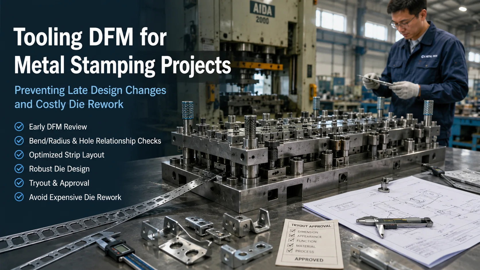
Production tooling becomes practical when a component can be blanked, pierced, bent, formed, or drawn from flat stock and is unlikely to change. Dies carry an upfront cost, but repeat production can spread that investment across the program. Material behavior, tolerances, and expected wear affect the business case. Late design changes may require substantial die rework, so functional testing and drawing approval should precede tooling release.

Before approving precision metal stamping and tooling services, request a manufacturability review covering material, thickness, forming feasibility, critical dimensions, secondary operations, lifetime quantity, and revision status. No universal production threshold proves that stamping will pay off.

Use a Hybrid Process When Only Critical Features Need Machining

The processes are not always competing choices. A stamped blank may create the outer profile, bends, and formed features, while tapping, reaming, grinding, or milling completes a critical interface.

The route works best when the stamped part provides repeatable locating datums and the secondary cycle is short. It is less attractive when forming distortion makes fixturing unstable or most features still require machining. A stamped PCB terminal block with secondary machining demonstrates the principle: its published route combines precision stamping, bending, tapping, drilling, and electroplating.


PCB terminal block manufactured through precision stamping, bending, tapping, drilling, and secondary machining processes

Why Stamping Tooling Does Not Always Pay Off

Account for Lifetime Demand, Changes, and Hidden Operations

A short product lifecycle, frequent customer revisions, or uncertain demand may not consume enough parts to recover the die investment. Model low, expected, and high lifetime quantities instead of relying on one optimistic annual forecast.

The stamped part’s completed cost must include deburring, tapping, machining, cleaning, plating, coating, inspection, assembly, packaging, tool maintenance, and possible modification. The quotation should state whether trials, sample inspection, revision rounds, sharpening, spares, storage, and maintenance are included. Changes after die construction begins can add cost and delay, making formal tooling release an essential control.

How to Calculate the Stamping Tooling Break-Even Point

Compare two fully defined manufacturing routes:

Break-even quantity = tooling investment ÷ (completed CNC unit cost − completed stamping unit cost)

“Completed” matters. CNC cost should include material, setup, machining, tools, inspection, finishing, and packaging. Stamping cost should include die design, trials, press production, material utilization, maintenance, secondary operations, inspection, finishing, and packaging.

If a stamped blank still needs CNC bores and threads, use the finished hybrid-part cost, not the press-only price. Test several volume scenarios. A small unit-cost difference creates a long payback period; a larger difference may justify tooling sooner.

Ask every bidder to quote the same drawing revision, material, quantity bands, inspection scope, finish, packaging, and tool ownership terms. Otherwise, quotations may cover different work. The right answer to “What production volume justifies stamping tooling?” is a project-specific break-even range, not an industry-wide number.

Is the CNC-Machined Part Suitable for Metal Stamping?

First determine whether the geometry can be produced from sheet or coil. Stamping cuts and forms flat stock, while machining removes material from a solid workpiece. Thick sections, enclosed features, or complex multi-plane geometry may not convert directly.

Separate Stampable Features From Critical Machined Features

Start with the stock form. Could the function use consistent sheet thickness? Review bends, draw depth, hole-to-edge relationships, springback, and burr-sensitive surfaces.

Classify drawing features into three groups: suitable for stamping, possible after a design or tolerance change, and still requiring machining. Precision bores, deep threads, sealing faces, bearing locations, and datum surfaces may remain secondary operations. Confirm locating datums, machining allowance, and how forming variation will affect the final setup. Secondary CNC machining is commonly used for high-precision bores and mounting faces on stamped components.

How to Move From a CNC Prototype to Stamped Production

A CNC prototype validates function, but not necessarily stampability. Its drawing may contain sharp corners, variable thickness, or tight tolerances created around machining rather than forming.

Freeze Requirements, Then Use DFM and First-Article Approval

Before hard tooling, confirm material, thickness, interfaces, critical dimensions, finish, and drawing revision. Projects still undergoing functional or customer-interface changes should remain in a flexible process until major risks are resolved.

A controlled transition follows this sequence: prototype validation, stamping DFM, production drawing revision, tool design, tool trial, sample inspection, correction, first-article approval, pilot run, and production release. Sample review should include burrs, cracks, wrinkles, springback, plating condition, appearance, and assembly performance, not dimensions alone.

What Buyers Should Include in a CNC-to-Stamping RFQ

An accurate quotation requires the current 2D drawing and STEP file, material and stock form, thickness, annual and lifetime quantities, current process, critical tolerances, finishing, secondary machining, inspection, packaging, and known changes.

Also compare tool ownership, storage, maintenance, sharpening, spare inserts, modification charges, transfer rights, and end-of-program handling. A low die price may create later cost if engineering changes or production support are excluded.

Choosing a Supplier for the CNC-to-Stamping Transition

A qualified supplier should evaluate both routes. Verify whether tooling is built internally, whether trial and production teams share responsibility, whether secondary work can be coordinated, and how first articles, revisions, tool wear, and corrective actions are controlled.

Zhejiang Chuangkai Mechanical and Electrical Technology Co., Ltd., also known as CK Metal Tech, combines tooling, metal stamping, CNC machining, surface treatment, inspection, and assembly within its integrated precision metal manufacturing scope. Its confirmed resources include 8 four-axis CNC machines, 18 precision CNC lathes, and Swiss-type machining capability. CK Metal Tech also produces progressive, drawing, and compound tooling and holds IATF 16949 certification. This supports full-CNC, full-stamping, and hybrid route reviews.

Conclusion

Stamping tooling pays off when the part is genuinely stampable, the design is stable, and lifetime savings exceed tooling, maintenance, validation, secondary processing, and revision risk. CNC machining remains useful for prototypes, changing designs, solid geometries, and precision features. A hybrid process may be the most balanced route when the base shape can be stamped but functional interfaces still require machining.

For a project review, prepare the latest drawing, STEP file, material, target quantity, program life, critical dimensions, secondary operations, and quality requirements. Those details allow CK Metal Tech to request a CNC-to-stamping DFM review and compare feasible routes without requiring an immediate tooling commitment.

FAQs

What production volume makes metal stamping cheaper than CNC machining?

There is no universal quantity. Calculate break-even from the actual tooling investment and the difference between completed CNC and stamping unit costs, including maintenance, secondary work, finishing, inspection, and design-change risk.

Can a CNC-machined part be converted directly to metal stamping?

Sometimes, but usually not without DFM. Solid sections, variable thickness, deep features, or tight tolerances may require redesign before tooling begins.

Do stamped parts still need CNC machining?

They may. Threads, precision bores, bearing fits, sealing faces, datum surfaces, or tight mounting features can require secondary machining, drilling, tapping, reaming, or grinding.

How can a buyer tell whether stamping tooling will pay off?

Confirm stampability, then compare completed lifecycle costs under low, expected, and high demand scenarios. The case is stronger when the design is frozen and hidden operations are included in both quotations.

What should be checked when choosing a stamping tooling manufacturer?

Check in-house tool design, DFM support, trials, first-article procedures, revision control, secondary machining, inspection, tool maintenance, ownership terms, and production quality management.

30th July 2026
Home
WhatsApp
Email
Contacts