CHUANGKAI

A Saya l A N D

Memuat

     
rumah // blog

blog

Sheet Metal Design for AI Server Racks and Data Center Cabinets: Strength, Airflow, Cooling Integration and RFQ Checklist


Sheet Metal Design for AI Server Racks and Data Center Cabinets Strength, Airflow, Cooling Integration and RFQ Checklist

AI server rack design must connect structural strength, airflow, cooling hardware, service access, and sheet metal manufacturability before drawings are released for quotation. A cabinet may fit every listed component yet still fail if rails deflect, exhaust air recirculates, cables block the rear path, or a late-added coolant manifold interferes with removable panels. The practical goal is to convert equipment loads and cooling architecture into a buildable data center cabinet design, a testable prototype, and an RFQ that different suppliers can quote on the same basis.

Define the Rack, Cabinet, and Cooling Scope Before Designing the Sheet Metal Structure

Distinguish AI Server Racks, Data Center Cabinets, and Aisle Containment

An open rack mainly supports equipment, rails, power distribution, and cables. A cabinet adds doors, side panels, top panels, access control, and a more controlled internal air path. Aisle containment is a room-level airflow system and should not be confused with the cabinet.

Buyers should identify responsibility for rails, filters, blanking panels, PDU brackets, cable accessories, grounding hardware, and final assembly. A rack fabricator may not cover containment panels, facility ducting, or coolant distribution equipment. Without a clear boundary, suppliers may quote different products under the same description.

Translate Air-Cooled, Liquid-Ready, and Hybrid Cooling into Mechanical Requirements

An air-cooled rack needs an unobstructed inlet and exhaust route. A liquid-ready design may also require manifold brackets, hose routing, quick-connect access, drip-management provisions, and service clearance. A hybrid rack must accommodate both liquid hardware and residual air-cooled loads.

ASHRAE recommends matching cooling architecture and airflow management to AI rack density and treating power and cooling as connected design decisions. Before freezing the sheet metal geometry, confirm the cooling method, component envelopes, service direction, and responsibility for thermal validation.

Design the Structure Around the Actual Load Path

Define Static Load, Center of Gravity, Anchoring, and Transport Conditions

Total equipment weight is only the starting point. Door-mounted hardware, PDUs, cables, manifolds, rear cooling assemblies, and extended service trays can change local loading and stability. State whether the cabinet will remain fixed, move on casters, be anchored, or ship with equipment installed.

The RFQ should identify installation orientation, lifting points, floor interfaces, service extension conditions, and transport expectations. A structure suitable for stationary use may not be suitable for loaded shipment. Missing these inputs prevents a defensible decision about reinforcement, base geometry, or connection design.

Select Material, Sheet Thickness, Stiffeners, and Joint Types

Increasing sheet thickness is not the only way to raise stiffness. Folded edges, return flanges, formed ribs, localized supports, closed sections, and shorter unsupported spans may control deflection with less added mass. The right route depends on cabinet size, openings, load location, production volume, and shipping method.

Structural Route Suitable Use Main Purchasing Checks
Welded frame Fixed installation requiring rigidity Distortion, datum control, finish access
Bolted frame Modular design or shipment in sections Joint security, alignment, repeat assembly
Hybrid structure Rigid load path with removable modules Tolerance stack-up and interface control

Any thickness or reinforcement proposal should be checked against the actual load case rather than copied from a standard enclosure.

Create a Controlled Airflow Path Through the Cabinet

Design the Front-to-Rear Air Path, Doors, and Leakage Control

For front-to-rear-cooled equipment, the intake area should align with server inlets and the rear zone should remain clear. Perforated doors must balance open area with stiffness, hinge loading, security, and filtration. A universal perforation percentage is unsuitable because pressure drop depends on pattern, occupied area, equipment fans, and system configuration.

Unused rack positions and panel gaps can create bypass airflow. Define blanking requirements, door seals, side clearances, and filter arrangements. Assess the prototype as an assembled cabinet with representative doors, rails, and components, not as isolated sheet metal parts.

Prevent Recirculation, Cable Blockage, and Top-of-Rack Hot Spots

Hot exhaust can return through open rack spaces, gaps around doors, top openings, or congested rear zones. Cable bundles, PDUs, crossmembers, and cooling hoses may also restrict exhaust flow.

Blanking panels, baffles, disciplined cable routes, and clear exhaust zones can reduce cabinet-level recirculation, but they cannot correct an unsuitable room layout.


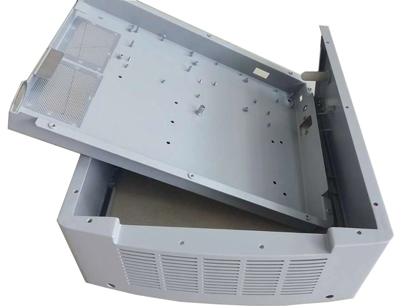
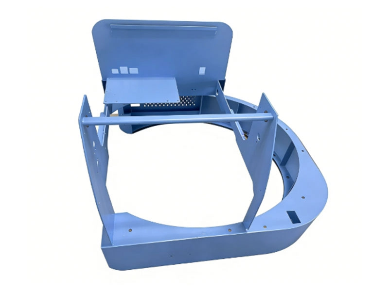
Medical and industrial equipment chassis assembly with cooling grilles and internal mounting rails

An industrial equipment chassis with cooling grilles and internal mounting rails shows how ventilation features, filters, supports, modular access, and assembly must be planned together. The referenced CK Metal Tech product serves medical, industrial testing, and communication applications, so it is a structural example rather than an AI rack performance claim.

Prepare the Cabinet for Cooling Components and Service Access

Plan Interfaces for Manifolds, Hoses, Fans, and Rear-Door Systems

A liquid-ready rack may need adjustable manifold brackets, controlled hose bend space, protected quick-connect locations, and separation between coolant paths and sensitive electrical areas. A rear-door heat exchanger or fan-assisted door may add weight to the hinge side and change rear service clearance.

Include component interface drawings, estimated weight, connection direction, removal path, and responsibility for brackets or purchased hardware. Adjustable interfaces may suit an evolving cooling system, but excessive adjustability can reduce stiffness and complicate repeat assembly.

Design Removable Panels for Maintenance, Inspection, and Replacement

Doors and panels should provide access without forcing technicians to disconnect unrelated cables or coolant lines. Review tool clearance, lifting method, panel weight, fastener retention, grounding continuity, and the sequence for removing a manifold, PDU, fan unit, or server.

More removable panels are not automatically better. Each joint can introduce alignment variation, leakage paths, and grounding requirements. Use removable construction where it supports real maintenance tasks and fixed structure where rigidity matters more.

Apply Sheet Metal DFM and Validate the Prototype

Control Bending, Welding, Fasteners, Tolerances, and Grounding Surfaces

Bend variation, weld shrinkage, hardware position, panel flatness, and coating buildup can combine into door, rail, or equipment-alignment problems. Drawings should identify functional datums, assembly-sensitive interfaces, grounding surfaces, masked threads, and dimensions that apply after finishing.

CK Metal Tech’s precision sheet metal manufacturing capabilities include CNC laser cutting, punching, bending, riveting, welding, grinding, and processing of several industrial sheet materials. Suitability depends on the drawing, dimensions, material, quantity, and inspection requirements. Buyers can also review powder coating vs wet painting for sheet metal parts when defining cosmetic areas, masking, grounding points, corrosion expectations, and assembly interfaces.

Validate Structure, Fit, Airflow, and Transport Before Repeat Production

Prototype approval should cover more than individual dimensions. A representative build may need rail alignment, door operation, panel fit, grounding continuity, equipment installation, cable routing, cooling-component clearance, and packaging review. Structural, airflow, and thermal testing responsibilities must be agreed before the order because a fabrication supplier may build to validated drawings without providing facility-level thermal engineering.

Before repeat production, freeze approved revisions, fixtures, inspection points, purchased components, packaging, and change-control rules. A successful hand-built sample does not prove repeatability without a defined production process.

Prepare the RFQ and Qualify a Sheet Metal Rack Manufacturer

Include the Technical Inputs Needed for a Comparable Quote

A custom server rack RFQ should include:

  • Controlled 2D drawings, 3D models, BOM, and revision status
  • Dimensions, equipment layout, rail interfaces, and component weights
  • Static, service, anchoring, lifting, and transport conditions
  • Air, liquid-ready, or hybrid cooling architecture
  • Door, cable, PDU, fan, filter, and manifold requirements
  • Material, finish, grounding, masking, and cosmetic specifications
  • Prototype quantity, production volume, inspection, assembly, and packaging scope

When the design is not frozen, request a DFM and prototype quotation rather than a production price based on unresolved assumptions.

Evaluate Supplier Capabilities, Evidence, and Red Flags

A qualified data center cabinet manufacturer should explain how cutting, bending, joining, finishing, inspection, trial assembly, and packaging remain controlled. Ask how functional datums are maintained, how cabinet-level fit is checked, which processes are subcontracted, and how revisions reach production.

Red flags include quotations without a revision, vague load assumptions, no review of cooling hardware, and no cabinet-level assembly check. Zhejiang Chuangkai Mechanical and Electrical Technology Co., Ltd., operating as CK Metal Tech, combines sheet metal processing, machining, stamping, surface finishing, and assembly through its kemampuan manufaktur logam presisi terintegrasi. Each AI server rack or data center cabinet still requires project-specific review.

Kesimpulan

A reliable AI server rack begins with a defined load path, controlled airflow, confirmed cooling interfaces, service access, and a manufacturing plan that accounts for bending, welding, hardware, finishing, and assembly. Generic sheet thickness, perforation percentages, or “liquid-ready” labels cannot replace application-specific review.

Buyers can submit drawings for a custom server cabinet manufacturing review with the 2D drawings, 3D model, BOM, dimensions, material, equipment weight, cooling configuration, target quantity, inspection scope, and packaging requirements. CK Metal Tech can then assess the requested route against its available fabrication and assembly processes.

Pertanyaan yang Sering Diajukan

How do I select sheet metal thickness for an AI server rack?

Thickness depends on the load path, unsupported span, openings, formed geometry, joint type, equipment weight, service conditions, and transport method. Review local deflection and interface stability rather than selecting thickness from total weight alone.

Does every AI server rack need liquid cooling?

No. The suitable architecture depends on heat output, rack density, facility conditions, server design, and operating plan. Air-cooled, liquid-ready, and hybrid configurations require different mechanical interfaces.

How can a server cabinet reduce hot-air recirculation?

Align intake and exhaust openings with the equipment, close unused rack spaces, reduce bypass gaps, keep cables and accessories out of the exhaust path, and coordinate the cabinet with aisle-level air management.

What information is needed for a custom server rack quote?

Provide drawings, BOM, dimensions, equipment layout and weight, cooling architecture, rail and accessory interfaces, material, finish, grounding, masking, quantities, inspection, assembly, and packaging requirements.

How do I choose a data center cabinet manufacturer?

Evaluate the manufacturing route, datum control, joining methods, finishing, cabinet-level assembly, inspection evidence, revision control, subcontractor management, prototype-to-production planning, and technical communication.

14th Agustus 2026

How to Source Semiconductor Equipment Frames and Enclosures: Supplier Qualification and RFQ Checklist


How to Source Semiconductor Equipment Frames and Enclosures Supplier Qualification and RFQ Checklist

Choosing a semiconductor equipment frame supplier requires more than comparing prices. A frame or enclosure may meet individual dimensions yet still create problems when doors, rails, panels, and internal modules are assembled. Buyers must connect design intent, manufacturing route, inspection, revision control, and capacity. This guide explains how to prepare a quote-ready RFQ, qualify a semiconductor equipment enclosure manufacturer, reduce dimensional and finishing risks, and select a supplier for prototype, NPI, or repeat production.

Define the Frame and Enclosure Scope Before Sending an RFQ

Distinguish Frames, Enclosures, Chassis, and Process Chambers

A welded frame normally carries loads and establishes equipment geometry. A sheet metal enclosure protects internal components and may include doors, removable panels, ventilation features, mounting rails, cable openings, and grounding points.

Process chambers are different because vacuum, process gases, controlled atmospheres, or special cleanliness requirements may demand capabilities beyond structural fabrication. The RFQ should separate manufactured parts, purchased components, customer-supplied items, and final assembly duties, including panel fitting, hardware installation, functional checks, and module-level packaging.

This distinction prevents a common sourcing error: selecting a capable general fabricator for a component that requires application-specific sealing, cleanliness, or validation. It also prevents missing costs when a quoted frame excludes the panels, hardware, purchased items, or assembly work needed to make it usable.

Identify Functional Datums, Interfaces, Loads, and Conditions

“High precision” is not a usable purchasing specification. Engineering teams should identify the surfaces, holes, rails, and interfaces that control installation or performance. These may include base mounting points, module interfaces, door openings, grounding surfaces, and alignment features.

The suitable structure depends on size, load, stiffness, weight, corrosion exposure, service access, and finishing requirements. Welded steel, formed sheet metal, aluminum structures, machined bases, and cast iron assemblies suit different conditions. A wafer dicing equipment cast iron frame assembly, for example, should be reviewed as a combined route involving structure, machined interfaces, inspection, and assembly rather than as a generic metal part.


Wafer dicing equipment cast iron frame assembly for semiconductor equipment

Before requesting quotations, buyers should confirm which features are functional datums, which surfaces contact other modules, and whether the supplier must verify the completed assembly rather than individual components.

Build a Quote-Ready Semiconductor Equipment Enclosure RFQ

Provide Controlled Drawings, Models, BOMs, and Revisions

A useful semiconductor equipment enclosure RFQ should include current 2D drawings, 3D models when available, a BOM, revision status, material requirements, and expected quantities. The 2D drawing should control tolerances, datums, finishes, inspection notes, and special requirements.

Identify the controlling file and require the quotation to state the reviewed revision. Customer-supplied parts, standard hardware, and supplier-purchased items must be marked clearly. Otherwise, two suppliers may appear to quote the same assembly while including different materials, fasteners, finishing operations, or inspection work.

When a design is still changing, request a DFM review and prototype quotation before asking for a firm production price. This allows the supplier to identify inaccessible welds, difficult bend sequences, coating conflicts, uncertain datums, and features that may require machining after fabrication.

Specify CTQs, Finish, Inspection, Volumes, and Packaging

Critical-to-quality characteristics should relate to function. Tightening every dimension may raise cost without improving assembly, while leaving mounting interfaces undefined can make a compliant frame unusable.

State prototype quantity, batch size, annual demand, material, surface finish, cosmetic zones, masking areas, grounding points, inspection records, labeling, and packaging. The supplier should know whether dimensions apply before or after coating and which threads, electrical contact areas, locating surfaces, or slots must remain free of buildup.

Packaging also belongs in the RFQ. Large frames may require defined lifting and restraint, while finished panels need protection against rubbing, edge impact, moisture, or mixed-part contact. These details help suppliers quote comparable scopes instead of hiding different assumptions behind different unit prices.

Evaluate the Supplier’s Complete Manufacturing Route

Review Structural Fabrication and Machined Interfaces

A semiconductor equipment frame manufacturer should explain the route from raw material to approved assembly. For a welded structure, that may include cutting, fixture setup, welding sequence, intermediate checks, correction, post-weld machining where needed, surface finishing, dimensional inspection, and trial assembly.

Ask how datums are established before welding, protected during fabrication, and verified afterward. Post-weld machining may be appropriate when welding cannot reliably hold a mounting surface or hole pattern, but it is not required for every design. The decision depends on structure, tolerance, access, and risk.

Critical outsourced operations should also be disclosed. Outsourcing is not automatically unsuitable, but the main supplier should explain specification control, batch identification, incoming verification, and responsibility for nonconforming work. The quotation should cover the completed manufacturing route rather than only the processes performed in-house.

Verify Enclosure Fabrication, Finishing, and Assembly

For equipment housings, check whether the supplier can connect cutting, bending, hardware insertion, welding, grinding, finishing, and assembly. CK Metal Tech’s precision sheet metal manufacturing capabilities include laser cutting, CNC punching, bending, riveting, welding, grinding, and processing of several commonly used industrial sheet materials. Suitability still depends on the drawing, material, size, finish, and inspection plan.

Buyers should confirm when doors, panels, hinges, rails, fasteners, and internal mounting features will be trial-fitted. Features affected by coating should be reviewed before finishing. Shipping separate parts without checking the assembled condition may transfer tolerance and fit problems to the equipment builder.

Where possible, prototype approval should include representative internal components or checking fixtures. This reveals whether the enclosure functions as an assembly, not merely whether each component passes an isolated measurement.

Prevent Distortion, Misalignment, and Assembly Failures

Control Weld Distortion and Protect Functional Datums

Welding creates local heating and uneven contraction. Joint layout, material thickness, restraint, and sequence can cause twisting, bowing, or movement at mounting interfaces.

Buyers should ask how fixtures locate the structure, how the welding sequence balances heat input, and which dimensions are checked before and after finishing. First-article inspection should prioritize mounting planes, hole patterns, diagonals, rail interfaces, and features that connect to other modules.

If final correction is the main control method, ask how it affects repeatability and whether the fixture, sequence, joint design, or machining plan needs revision. Correction may produce an acceptable prototype without proving that the same route will remain stable across repeat batches.

A suitable supplier should be able to connect the drawing’s functional requirements with a practical fabrication and measurement plan.

Prevent Tolerance Stack-Up and Coating Interference

Assembly problems often result from several small deviations rather than one defective part. Bend location, bend angle, welded position, inserted hardware, hole size, and coating buildup can accumulate across an enclosure.

Doors may rub, rails may shift, modules may not align, or grounding points may become insulated. Drawings should distinguish finished dimensions from pre-coating dimensions and identify masked areas, threaded holes, contact surfaces, and assembly-sensitive slots.

Prototype approval should include fitting of doors, panels, hardware, and representative internal components where practical. For repeated interfaces, review tolerance accumulation instead of tightening every feature. Adjustment slots, locating tabs, machined references, or controlled assembly points may provide a more stable solution than imposing excessive tolerances on all sheet metal dimensions.

Verify Inspection, Traceability, and Engineering Changes

Define Evidence and Control Nonconformance

Inspection requirements should match risk. A first article may include a dimensional report, material records, finish verification, photographs, or CMM data for selected features. The RFQ should identify full-report, sampling, and functional-check requirements.

For large structures that cannot be measured in one setup, review the proposed method before production. The supplier should explain how separate measurements maintain a reliable relationship to the defined datums.

Supplier qualification should also confirm how obsolete drawings are removed, batches are identified, and deviations, substitutions, rework, or repairs receive approval. Engineering changes may affect finished inventory, work in process, purchased components, fixtures, inspection programs, and packaging documents.

SEMI describes standards as technical agreements used in purchase specifications and equipment evaluations, while traceability is an established SEMI standards subject. This supports defining project-specific documentation rather than assuming that the word “semiconductor” creates one universal inspection package.

Compare Suppliers Before Awarding the Order

A supplier that produces one acceptable prototype may not be ready for repeat production. NPI needs engineering communication and flexible planning; repeat production adds fixture control, stable inspection, capacity planning, subcontractor control, and disciplined change management. Compare the complete route, not only unit price.

Qualification Area What the Buyer Should Confirm
Application fit Similar size, material, processes, and assembly risk
Manufacturing route Clear sequence through fabrication, finishing, inspection, and packaging
Datum control Method for protecting and measuring functional interfaces
Quality evidence Appropriate first-article, material, finish, and inspection records
Change control Revision, deviation, rework, and obsolete-inventory procedures
Capacity Fit for prototype, pilot batch, and expected repeat demand
Komunikasi Technical contact and documented review of assumptions

Red flags include vague answers about datums, excluded critical processes, uncontrolled subcontracting, missing revision references, and no trial-assembly plan. Depending on project risk, the next step may be a technical review, supplier audit, first article, pilot batch, or production approval.

How CK Metal Tech Supports Frame and Enclosure Projects

Zhejiang Chuangkai Mechanical and Electrical Technology Co., Ltd., operating as CK Metal Tech, combines precision sheet metal processing, machining, metal stamping, surface treatment, and component assembly. Its kemampuan manufaktur logam presisi terintegrasi can support build-to-print projects requiring connected fabrication steps, and the company website lists a wafer dicing equipment cast iron frame assembly among its products.

This capability range does not replace project qualification. Buyers should submit drawings, material, functional datums, finish, target quantity, inspection requirements, and operating conditions so CK Metal Tech can review whether the requested route fits the available processes and identify points requiring clarification.

Kesimpulan

Successful semiconductor equipment frame sourcing starts with a controlled specification, not a supplier shortlist. Define the assembly boundary, functional datums, manufacturing route, finish, inspection evidence, change control, production stage, and packaging before comparing prices. A qualified supplier should explain how those requirements remain connected from first article through repeat production.

For a project-specific review, buyers can submit drawings and RFQ requirements to CK Metal Tech with the 2D drawing, 3D model, BOM, material, quantity, application, critical interfaces, finish, and inspection expectations. Samples or failure photographs can help focus the review.

Pertanyaan yang Sering Diajukan (FAQ)

What files are needed to quote a semiconductor equipment frame?

Provide current 2D drawings, a 3D model when available, BOM, revision, material, finish, quantities, critical datums, inspection requirements, packaging, and delivery location. Identify the controlling document and explain unresolved assumptions.

Does every semiconductor equipment enclosure require cleanroom assembly?

No. It depends on installation location, exposure to sensitive processes, customer specifications, particle risk, and downstream assembly. Cleanliness, ESD controls, packaging, and permitted residues should be stated explicitly.

What tolerances should be specified for a welded equipment frame?

Focus on mounting planes, module interfaces, hole patterns, rails, and other functional datums. Wider limits may suit nonfunctional dimensions. The supplier should review whether welding, correction, or post-weld machining can hold each requirement.

When should a welded frame be machined after welding?

Post-weld machining may be suitable when critical mounting surfaces or hole locations cannot be held consistently through fabrication and correction alone. The decision depends on frame size, stiffness, access, tolerance, material, and measurement method.

How should buyers compare semiconductor equipment enclosure suppliers?

Compare drawing review, fabrication route, datum control, finishing, trial assembly, inspection records, revision control, capacity, subcontractors, packaging, and technical communication. Confirm essential operations and documents are included.

13th Agustus 2026

How to Control Runout in Long Shaft Machining: Setup, Grinding, and Inspection for Parts Up to 4 Meters


How to Control Runout in Long Shaft Machining Setup, Grinding, and Inspection for Parts Up to 4 Meters

Long shaft machining becomes difficult when a part passes diameter inspection but still shows excessive runout, bow, taper, vibration, or assembly misalignment. The cause may begin in the raw material, appear during stock removal, develop after heat treatment, or result from an inspection setup that does not reproduce the drawing datum. For shafts approaching four meters, material condition, workholding, machining sequence, grinding, inspection, and packaging must form one controlled process.

Long Shaft Machining Runout: Diagnose the Pattern First

Runout is commonly checked by rotating the shaft through 360 degrees and comparing the indicator’s maximum and minimum readings at a specified position. The result is meaningful only when the datum, support method, gauge position, and permitted value are defined.

Observed condition Check first Next action
Runout is concentrated near one end Center holes, chucking, tailstock, datum transfer Verify the setup axis
Maximum bow appears near the middle Support spacing, stock straightness, cutting force Review support and roughing
Diameter changes along the shaft Tailstock alignment, tool wear, thermal drift Separate geometric and thermal error
Runout increases after heat treatment Residual stress, support, remaining allowance Recheck straightness before finishing
Inspection reports disagree Datum, support points, orientation, gauge position Agree on one method

This identifies whether the next review should focus on material, setup, grinding, or measurement.

Why Long Shafts Develop Runout, Taper, and Straightness Errors

Material Straightness, Residual Stress, and Heat-Treatment Distortion

A long bar may contain initial bow or uneven residual stress. Heavy material removal can release that stress and move a shaft that appeared straight during roughing. Thin sections, keyways, and large diameter changes increase the risk.

For parts requiring substantial stock removal or heat treatment, a staged route may be safer than machining directly to final size. Rough turning establishes the geometry, followed by a stability or heat-treatment step when specified, another straightness check, and finish machining. Remaining allowance should be distributed so final turning or grinding does not need to correct most of the error from one side.

The RFQ should identify material grade, supply condition, heat treatment, hardness, and incoming straightness requirements.

Cutting Force, Unsupported Length, Clamping, and Heat

A slender shaft deflects under radial cutting force. As unsupported length increases, the tool may push the workpiece away, causing taper, barrel shape, chatter, or inconsistent diameter. Excessive chuck, tailstock, or steady-rest pressure can also bend the shaft before cutting.

Lower cutting force, short tool overhang, staged passes, controlled support, and temperature management reduce risk. A strategy that works on a rigid section may fail at the smallest diameter. Buyers should ask how the supplier will support that section, manage tool wear and thermal growth, and perform in-process checks.

Choosing the Right Setup for Long Shaft Turning

The setup should reflect shaft length, diameter, weight, material, critical datums, and permitted runout. Buyers can review CK Metal Tech’s long shaft CNC machining and grinding capabilities before submitting a drawing.

Between-Centers Turning and Tailstock Alignment

Turning between centers can preserve one rotational axis through several operations when center holes remain available as process datums. It is useful when multiple journals must relate to the same axis, although end geometry, weight, or feature access may require another setup.

Center holes must be prepared and protected because inconsistent seating transfers into runout. Tailstock alignment and thrust also matter: insufficient support permits movement, while excessive force may bow a slender shaft. The supplier should check initial indicator readings, explain how the part will be reloaded, and confirm whether center holes are temporary process features or drawing-controlled features.

Steady Rest vs. Follow Rest

A steady rest supports the shaft at a fixed position; a follow rest moves with the cutting tool. The correct choice depends on where the unsupported span develops.

Official machine guidance describes steady rests as support for long or narrow shafts and instructs operators to adjust rollers without causing workpiece deflection. It also recommends rotating the part and checking it with an indicator after adjustment.

Rollers that are too loose provide little control; rollers that are too tight can create friction, marks, heat, or artificial bending. The supplier should identify support locations and explain how alignment will be rechecked after repositioning.

Machining Sequence for Controlling Long-Shaft Runout

Rough Turning, Stability Review, and Finish Turning

A sound process separates heavy stock removal from final geometry control. Rough turning establishes the shape and reveals how the blank responds as material is removed. The shaft can then be checked for bow and datum movement before heat treatment, semi-finishing, or grinding.

A typical route is:

Material review → datum preparation → rough turning → stability or heat-treatment step → straightness review → semi-finishing → finish turning or grinding → final inspection.

The exact route depends on material, geometry, hardness, and drawing requirements. Repeated chucking should be minimized or controlled through consistent center holes, journals, or other process datums.

When Grinding Is Required—and When Turning Is Enough

Grinding may suit hardened journals, bearing fits, wear surfaces, or requirements involving surface condition, roundness, cylindricity, and relationships between diameters. It should not be added automatically. If finish turning meets the drawing, another setup may add cost and datum-transfer risk.


Precision shaft components manufactured with CNC turning and grinding processes for long shaft machining applications

For ground shafts, confirm the grinding datum, support method, allowance, heat-treatment sequence, and equipment range. CK Metal Tech’s komponen poros yang diproses dengan presisi dan digerinda use a published route combining precision turning, grinding, and quenching for custom alloy-steel or stainless-steel designs.

This product does not establish a four-meter grinding range. Maximum length, diameter, weight, and geometry must be verified for each drawing.

How to Inspect Runout and Straightness on a Long Shaft

Define the Datum Axis Before Selecting the Gauge

Circular runout, total runout, straightness, roundness, and coaxial relationships describe different conditions. A shaft may meet diameter tolerance while failing rotational function. The drawing should identify the functional datum axis and the characteristic that affects assembly.

The datum may come from center holes, two bearing journals, or another functional feature. Measuring one section does not prove the complete shaft meets total runout or straightness requirements. Reports should state the datum, support method, gauge positions, orientation, rotation method, and result.

Control Gravity Sag and Measurement Support

A long slender shaft can sag under its own weight during horizontal inspection. Between-centers measurement, rollers, V-blocks, and coordinate measurement systems may produce different readings if support positions and datums are not correlated.

Inspection equipment must match the workpiece envelope, weight, access, and required uncertainty. A CMM may suit some features, but it should not be assumed that every machine can accommodate a complete four-meter shaft. Supplier and buyer should agree on support spacing, orientation, rotation method, and measurement correlation.

CK Metal Tech has CMM, 2.5D measurement, metallographic, and hardness-testing resources, but the method for a full-length four-meter shaft must be confirmed against the equipment range.

Troubleshooting Long-Shaft Machining Defects

Runout near one end points first to the chuck, center hole, tailstock, or datum transfer. Maximum bow near the middle suggests stock straightness, support spacing, cutting force, or stress release. Gradual taper calls for checks of alignment, tool wear, machine geometry, and temperature. Periodic chatter may indicate poor rigidity, unsuitable speed, excessive tool overhang, or unstable rest contact.

If runout increases after heat treatment, verify straightness before removing final allowance. If grinding introduces new error, review grinding heat, support pressure, wheel condition, and datum correlation. Rework should not begin until the cause and remaining allowance are understood.

RFQ Checklist for Long Shafts Up to 4 Meters

Drawing, Material, and Application Data

Provide the current 2D drawing and 3D model, total and effective machining lengths, maximum and minimum diameters, estimated weight, material grade and condition, center holes, functional datums, and all stepped, threaded, tapered, keyed, or drilled features.

State circular runout, total runout, straightness, surface requirements, heat treatment, hardness, grinding scope, and inspection records. Application details such as speed, load, mating components, and environment help identify critical features. Include quantities and any photographs or reports from an existing defect.

Capacity, Inspection, and Packaging Questions

Ask the supplier to confirm usable between-centers length, maximum diameter and weight, lifting method, tailstock and rest configuration, and which turning, heat treatment, grinding, and inspection stages are internal or outsourced. Confirm grinding range rather than assuming it matches turning capacity.

The quotation should identify datum simulation, inspection supports, sample and production setups, and packaging. A shaft that passes inspection can still bend if supported incorrectly during storage or transport.

How to Choose a Long Shaft Machining Supplier

Evaluate the Complete Manufacturing Route

A suitable supplier should explain how material review, datum preparation, roughing, support, heat treatment, finishing, grinding, inspection, and packaging connect. The review should identify where straightness is checked, how setups are repeated, which features establish the final axis, and what happens if the shaft moves after heat treatment.

Buyers should confirm whether first articles and production parts use the same route, which records are available, and how abnormal results are handled. Confirming machine length without discussing weight, support, grinding, and inspection is not a complete feasibility review.

Relevant CK Metal Tech Capabilities

Zhejiang Chuangkai Mechanical and Electrical Technology Co., Ltd. connects machining with related processes through its kemampuan manufaktur logam presisi terintegrasi. Buyers can also review Tentang Zhejiang Chuangkai Mechanical and Electrical Technology Co., Ltd. when evaluating the supplier.

Confirmed resources include 18 precision CNC lathes, turning capacity for workpieces up to approximately four meters, internal and external cylindrical grinding, centerless grinding, thread rolling, tapping, and drilling. CK Metal Tech also holds IATF 16949 certification, while its website presents machining, stamping, sheet-metal fabrication, surface treatment, and assembly as connected services.

Maximum diameter, weight, grinding length, support arrangement, and achievable runout or straightness must still be verified for each project.

Kesimpulan

Controlling runout in long shaft machining requires more than a long-bed lathe. Material condition, datums, support pressure, cutting force, heat treatment, grinding, inspection, and transport must form one traceable route. The objective is to meet the drawing under an agreed measurement method, not to promise “zero runout.”

For a process review, submit the drawing, material, length, diameters, estimated weight, runout and straightness requirements, heat treatment, grinding scope, quantity, application, and any defect photographs or reports. Buyers can request a long shaft machining review dari CK Metal Tech.

Pertanyaan yang Sering Diajukan

How can runout be reduced when machining a long shaft?

Check raw-material straightness, datums, chuck and tailstock alignment, support location, cutting force, tool condition, and temperature. Separate roughing from finishing when stress release is likely, then inspect with the agreed datum and support method.

When is a steady rest required for long shaft turning?

A steady rest may be needed when the unsupported span permits deflection, vibration, or unstable size. The decision depends on diameter, length, weight, material, cutting force, geometry, and tolerance.

Should a long shaft be ground after CNC turning?

Grinding is appropriate when hardness, bearing fits, wear surfaces, roundness, cylindricity, or surface requirements cannot be met reliably by turning. It may be unnecessary when finish turning satisfies the drawing.

How is total runout measured on a four-meter shaft?

Define the datum axis, support arrangement, rotation method, and measurement locations. The method must consider gravity sag, equipment range, and correlation between supplier and customer inspection.

What information is needed for a long shaft machining quote?

Provide drawings, material condition, length, diameters, weight, datums, runout and straightness tolerances, surface requirements, heat treatment, grinding, features, quantities, application, inspection records, and packaging expectations.

7th Agustus 2026

3-Axis vs 4-Axis CNC Machining: When Does a Rotary Axis Reduce Setups and Datum Error?


3-Axis vs 4-Axis CNC Machining When Does a Rotary Axis Reduce Setups and Datum Error

Choosing between 3-axis and 4-axis CNC machining should begin with the drawing, not the machine list. A rotary axis can expose several sides of a component without manual flipping, which may reduce fixture changes, repeated probing, and datum transfer. It does not automatically make every part more accurate or less expensive. The correct route depends on feature direction, tool access, cross-face tolerances, workholding, quantity, and inspection.

3-Axis or 4-Axis CNC Machining? Quick Decision Guide

Map every machined feature by direction, then identify which features must remain related to the same functional datum.

Decision factor 3-axis machining often fits 4-axis machining often fits
Feature direction One or two accessible directions Three or more sides or radial directions
Cross-face relationships Moderate or fixture-repeatable Tight relationships around a common datum
Rotary features Limited and easy to re-fixture Radial holes, circular slots, angular patterns
Quantity Prototype, low volume, changing design Stable pilot or repeat production
Setup plan One or two direct setups Several 3-axis setups can be consolidated

The process should be reviewed against the actual part, not specified only as “4-axis required.” Buyers can examine CK Metal Tech’s precision CNC machining capabilities when a drawing needs process review.

Choose 3-Axis Machining for Accessible, Single-Direction Features

Three-axis machining remains practical for plates, brackets, flanges, and simpler housings whose critical features are accessible from the top or one additional flipped orientation. A qualified flip fixture and probing can make a second setup repeatable enough for many drawings.

It is often more economical for prototypes, low quantities, or changing designs. Buyers should still ask how many times the part will be clamped, which datum is used, and where cross-face dimensions will be inspected.

Choose 4-Axis Machining for Multi-Sided or Rotary Features

Four-axis machining becomes more relevant when holes, slots, flats, or mounting faces are distributed around a part, or when cylindrical features require controlled angular spacing. Rotating the workpiece can give the tool access to several directions while preserving one primary clamping relationship.

Autodesk identifies multi-sided, cylindrical, and wrapped geometry as common 4-axis applications and notes that less re-clamping can reduce cumulative setup error. Undercuts or compound angles may still require 5-axis machining or another process.

How Multiple Setups Create Datum Shift and Positional Error

Re-Clamping, Re-Zeroing, and Fixture Stack-Up

Every new setup introduces variables such as debris under a locator, fixture error, clamping deformation, probe variation, work offsets, and inconsistent seating. Their combined effect can appear in features produced from different setups.

A part may pass individual checks yet fail cross-face position, perpendicularity, or center distance. Multiple setups remain acceptable when tolerance and fixture repeatability support them. Clear datums, probing, and first-article checks reduce risk.

Why 4-Axis Machining Reduces—but Does Not Eliminate—Error

Keeping the part clamped while it indexes removes some manual handling and repeated zero-setting. Autodesk describes this as a reason 4-axis machining can reduce misalignment and cumulative tolerance error.

The rotary setup still has an error chain. The workpiece must match the rotation center; the fixture must resist eccentric loading; and indexing, offsets, heat, and clamping must be controlled. Autodesk support identifies an incorrect work-coordinate position relative to the rotary center as a cause of wrong 4-axis output.

Part Geometry and GD&T Requirements That Drive Axis Selection

Multi-Sided Holes, Slots, Flats, and Mounting Features

Strong 4-axis candidates often contain features on adjacent or opposite faces that share a critical relationship. Examples include mounting holes around a housing, flats indexed at specified angles, or several faces referenced to one bore.

The drawing should identify which features control assembly. Position, perpendicularity, parallelism, and profile across faces may justify one rotary setup. If these relationships are loose, a 3-axis flip fixture may be sufficient. Buyers should mark cross-face critical dimensions and ask how each will be produced and measured.

Cylindrical, Wrapped, and Repeating Angular Features

Radial holes, circumferential grooves, engraving, and angular patterns are natural rotary-axis applications. Indexed machining positions the workpiece at defined angles; wrapped or simultaneous motion may be needed for a continuous path around a cylinder.


Four-axis CNC machined motor housing with annular cooling grooves for multi-sided machining applications

A relevant example is a four-axis CNC-machined motor housing made from high-strength aluminum alloy. Its published annular cooling grooves and mounting holes illustrate why rotary access may suit cylindrical and installation features. The page does not provide setup savings or tolerance comparisons.

Indexed 3+1 vs Simultaneous 4-Axis Machining

When Indexed 4-Axis Machining Is Sufficient

In indexed, or 3+1, machining, the rotary axis moves the part to a fixed angle and stops. Standard 3-axis toolpaths then machine that orientation. Autodesk separates this method from continuous rotary cutting.

It suits bolt patterns, radial holes, flats, pockets, and mounting features at known angles. It is generally easier to program and inspect than simultaneous motion. A quote should state indexed positions, feature groups, support, and remaining setups.

When Simultaneous Rotary Motion Is Required

Simultaneous 4-axis machining moves the rotary axis while cutting. It may fit helical grooves, wrapped contours, or free-form cylindrical surfaces that cannot be produced efficiently by fixed indexing. Autodesk notes that these workflows require rotary-orientation control, clearance planning, and collision avoidance.

The machine configuration, CAM strategy, postprocessor, rotary direction, and collision model must agree. Not every “4-axis” machine supports the same continuous strategies. Buyers should specify the required geometry rather than demand simultaneous motion by default.

3-Axis vs 4-Axis CNC Machining Cost

Compare Completed-Part Cost, Not Machine Hourly Rate

A 4-axis machine may have a higher hourly rate, but the completed part may cost less if it replaces fixtures, setups, transfers, and intermediate inspection. A simple component may cost more because of added programming, alignment, and workholding.

A fair comparison includes programming, fixtures, setup labor, cycle time, tooling, inspection, first-article approval, and rework risk. Separate one-time charges from recurring unit costs, and require the same finished scope.

Prototype, Pilot, and Repeat Production Decisions

A prototype may be produced efficiently in two 3-axis setups while the design is changing. After interfaces and quantities stabilize, a rotary fixture may become worthwhile for pilot or repeat production. The break point depends on fixture cost, setup time, inspection effort, geometry, and lifetime quantity.

Changing the route can alter datum flow, tool marks, burr location, and measurement. If prototype and production methods differ, critical characteristics need renewed pilot-run validation.

Common 4-Axis Machining Risks and How to Prevent Them

Rotary Centerline, Workholding, and Orientation Errors

If the programmed coordinate system does not match the actual rotary centerline, features can shift as the part turns. Fixture eccentricity may create changing tool engagement, vibration, and angular error. A reversed rotary direction or incorrect zero can mirror or misplace wrapped features.

Controls include probing the centerline, checking indicator readings, simulating the machine and fixture, verifying the postprocessor, and inspecting a first article at several angular positions.

Tool Access, Collision, Rigidity, and Part Deformation

Rotating the part changes the collision environment. A tool, holder, spindle, chuck, fixture, or tailstock that clears at zero degrees may interfere at another angle. Long tools may reduce rigidity and offset the benefit of fewer setups.

Thin-wall housings and long or eccentric parts can deform under rotary clamping. DFM should review clamping zones, support, tool reach, clearance, and material-removal sequence. Some features may remain safer as a separate 3-axis operation.

RFQ Checklist for a 3-Axis vs 4-Axis Process Review

Drawing, Datum, and Application Information

Provide the current 2D drawing and STEP file, material and condition, datum system, cross-face positional tolerances, angular features, cylindrical surfaces, surface requirements, and the features that control assembly. Include prototype quantity, annual demand, inspection documents, and packaging needs.

If an existing route is failing, attach its setup description, inspection report, and photographs of the nonconforming feature.

Setup, Fixture, and Inspection Questions

Ask each supplier to state:

  • The proposed number of setups
  • Whether the route is 3-axis, indexed 3+1, wrapped, or simultaneous 4-axis
  • Which features remain in one clamping
  • The rotary-axis direction and workholding concept
  • Whether auxiliary support is needed
  • How cross-face GD&T will be inspected
  • Whether samples and production use the same route
  • Which fixture and first-article charges are one-time costs

How to Choose a 3-Axis and 4-Axis CNC Machining Supplier

Verify the Process Plan, Not Only the Machine List

A machine list does not show whether a supplier can select the correct route. A useful review identifies feature directions, datum flow, tool access, fixture risk, and inspection before quotation.

Ask for a simplified setup map and the reason behind the axis selection. The supplier should recommend 3-axis machining when it is more direct and 4-axis machining when reduced handling creates an advantage. Confirm rotary-centerline and first-article controls.

Relevant CK Metal Tech Capabilities

Zhejiang Chuangkai Mechanical and Electrical Technology Co., Ltd., also known as CK Metal Tech, supports drawing-based projects through its kemampuan manufaktur logam presisi terintegrasi. Confirmed resources include eight 4-axis CNC machines, four CNC milling machines, and 4-axis capacity for larger workpieces up to approximately 1.8 meters, subject to geometry, diameter, weight, fixture, and tool-access requirements.

The company also has CMM and 2.5D inspection resources and holds IATF 16949 certification. CK Metal Tech’s machining scope includes milling, turning, grinding, drilling, and related operations. Specific rotary mode, work envelope, positional capability, and inspection method should be verified against each drawing.

Kesimpulan

The decision between 3-axis and 4-axis CNC machining should follow three steps: map the required machining directions, identify cross-face dimensions that depend on a common datum, and compare complete setup, fixture, programming, and inspection cost. A rotary axis can reduce re-clamping risk, but only when the centerline, workholding, program, and inspection plan are controlled.

Buyers can request a 3-axis vs 4-axis process review by submitting the drawing, STEP file, material, datum system, cross-face tolerances, circular features, quantity, and any existing setup or inspection report.

Pertanyaan yang Sering Diajukan

Does 4-axis CNC machining always improve accuracy?

No. It can reduce manual re-clamping and datum transfer, but accuracy still depends on the rotary centerline, fixture, machine condition, work offsets, toolpath, heat, and inspection method.

When is 3-axis machining more cost-effective?

It is often more economical when features are accessible from one or two directions, quantities are low, the design is changing, and cross-face tolerances can be controlled with a direct fixture.

What is the difference between 3+1 and simultaneous 4-axis machining?

In 3+1 machining, the rotary axis positions the part and remains stationary during cutting. In simultaneous machining, the rotary axis moves continuously while the tool follows the programmed path.

Can a 3-axis machine produce multi-sided parts?

Yes. The part can be flipped or moved to another fixture. Suitability depends on setup count, fixture repeatability, cross-face tolerances, quantity, and datum-transfer risk.

What information is needed for a 4-axis CNC machining quote?

Provide drawings, a STEP file, material, datums, cross-face GD&T, radial or circular features, surface requirements, quantities, application details, and inspection expectations.

6th Agustus 2026

Pemesinan Swiss vs. Pembubutan CNC: Cara Memilih untuk Poros Kecil, Pin, dan Komponen Ramping

Permesinan Swiss vs. Pembubutan CNC: Cara Memilih untuk Poros Kecil, Pin, dan Bagian Tipis


Memilih antara pemesinan Swiss dan pembubutan CNC konvensional menjadi sulit ketika gambar berisi diameter kecil, bagian panjang yang tidak ditopang, persyaratan runout yang ketat, atau fitur sekunder. Pilihan tergantung pada penopang, panjang pemotongan, kondisi bahan, kompleksitas fitur, toleransi, dan kuantitas. Panduan ini membantu para insinyur dan tim pengadaan mengevaluasi poros, pin, selongsong, konektor, dan bagian ramping lainnya tanpa bergantung pada aturan tetap.

Pemesinan Swiss atau Pembubutan CNC? Panduan Pemilihan Cepat

Keputusan pertama harus didasarkan pada geometri dan risiko proses, bukan asumsi bahwa mesin tipe Swiss lebih akurat. Pembeli dapat meninjau CK Metal Tech. Kemampuan pembubutan CNC presisi dan permesinan Swiss. ketika kedua jalur tersebut perlu dievaluasi.

Kondisi proyek Mesin Swiss seringkali cocok. Pembubutan CNC konvensional seringkali cocok
Diameter kecil dengan penampang panjang dan ramping. Dukungan dapat tetap berada di dekat zona pemotongan. Hal ini mungkin terjadi jika penahan benda kerja dan strategi pemotongan mengontrol defleksi.
Bagian yang pendek, kaku, dan sederhana. Mungkin menambah pengaturan yang tidak perlu. Seringkali rute yang lebih langsung
Lubang silang, permukaan datar, alur, atau pengerjaan balik Berguna ketika mesin menggabungkan operasi. Praktis jika pekerjaan sampingan tetap ekonomis.
Volume rendah atau tidak pasti Tergantung pada pengaturan dan fitur. Seringkali lebih mudah untuk dibenarkan
Produksi berulang yang stabil Dapat mengurangi penanganan antar operasi. Kompetitif untuk geometri yang lebih sederhana
Kelurusan atau diameter batang yang bervariasi Stok harus sesuai dengan bushing pemandu. Mungkin kurang sensitif, tergantung pada cara memegang benda kerja.

Pilih Pemesinan Swiss untuk Komponen Berdiameter Kecil, Ramping, dan Multifungsi.

Pemesinan Swiss umumnya dipertimbangkan ketika suatu komponen bengkok atau bergetar saat pahat bergerak menjauh dari titik penjepitan utama. Dalam operasi pemandu-bantalan, batang ditopang dekat dengan area pemotongan sementara kepala mesin mengumpan material melalui pemandu. Hal ini dapat mengurangi panjang bagian yang tidak ditopang selama pemotongan dan cocok untuk pin presisi panjang, poros bertingkat sempit, dan bagian-bagian yang halus.

Mesin ini juga berguna ketika pengerjaan bubut, pengeboran silang, penggilingan, pembuatan ulir, atau pengerjaan balik dapat dikombinasikan. Pembeli harus memverifikasi konfigurasi mesin yang sebenarnya. Mesin bubut tipe Swiss dapat beroperasi dengan atau tanpa bushing pemandu, sementara perkakas aktif, fungsi sub-spindel, dan ukuran batang yang dapat digunakan bervariasi. Spesifikasi yang dipublikasikan mengkonfirmasi bahwa mesin bubut Swiss yang dapat diubah dapat mendukung pengoperasian dengan bushing pemandu dan gaya chucker.

Pilih Pembubutan CNC Konvensional untuk Komponen yang Lebih Pendek, Lebih Besar, atau Lebih Sederhana

Pembubutan CNC konvensional tetap praktis untuk komponen yang kaku, profil luar yang sederhana, diameter yang lebih besar, kuantitas yang lebih rendah, atau gambar yang kemungkinan akan berubah. Pin pendek dengan satu diameter dan ulir dasar mungkin tidak membenarkan pengaturan Swiss.

Mesin bubut dengan kepala tetap juga dapat menghasilkan komponen ramping menggunakan penyangga ekor, penahan tetap, pemotongan bertahap, dan perkakas dengan gaya rendah. Pertanyaannya adalah apakah langkah-langkah tersebut menghasilkan komponen yang stabil. Koreksi berulang, beberapa pengaturan, atau penyimpangan putaran yang tidak konsisten membenarkan peninjauan kembali pemesinan Swiss. Jika komponen tetap stabil, mengganti peralatan mungkin akan menambah biaya tanpa meningkatkan kualitasnya.

Mengapa Dukungan Benda Kerja Mengubah Akurasi pada Bagian yang Ramping

Penopang Bushing Pemandu vs Penjepit Benda Kerja Kepala Tetap

Poros yang ramping akan melentur ketika gaya potong radial bekerja pada bagian yang tidak ditopang. Hasilnya dapat berupa kemiringan, getaran, perubahan diameter, kelurusan yang buruk, atau permukaan yang tidak konsisten. Risiko meningkat ketika bagian terlemah berada jauh dari chuck atau mengandung tegangan sisa.

Bushing pemandu mengurangi jarak antara pahat dan penyangga, tetapi tidak menghilangkan keausan pahat, panas, variasi bahan, jarak bebas, atau masalah urutan pengerjaan. Pembubutan konvensional mungkin tetap cocok jika penahan belakang atau penahan tetap menopang benda kerja tanpa fitur penghalang. Pembeli harus menanyakan bagaimana benda kerja akan dipegang dan apakah produksi menggunakan pengaturan yang sama.

Kelurusan Batang Baja, Variasi Diameter, dan Kesesuaian Bushing Pemandu

Dalam pemesinan bantalan pemandu, diameter batang, kebulatan, kelurusan, dan kondisi permukaan memengaruhi pengumpanan dan kontak. Jarak bebas yang berlebihan dapat melemahkan penyangga; jarak bebas yang tidak cukup dapat menyebabkan gesekan, masalah pengumpanan, atau bekas pada permukaan.

Persyaratan bahan baku bergantung pada mesin, material, geometri, dan mode operasi. Beberapa mesin bubut Swiss konvertibel dapat beroperasi tanpa bushing pemandu dan menggunakan batang tarik untuk bagian yang lebih pendek, sementara pekerjaan dengan bushing pemandu mungkin memerlukan bahan baku yang lebih terkontrol. Informasi SS20 Tsugami membedakan operasi bushing pemandu tradisional dari operasi chucker opsional, menunjukkan mengapa RFQ harus menyatakan kondisi material dan bukan hanya tingkat paduan.

Bagaimana Geometri dan Toleransi Bagian Menentukan Proses Pembubutan yang Tepat

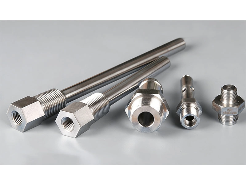
Komponen poros presisi yang diproduksi dengan pembubutan CNC, penggerindaan, dan perlakuan panas untuk aplikasi industri.


Evaluasi Diameter, Panjang Efektif, dan Rasio Panjang terhadap Diameter Secara Bersama-sama

Rasio panjang terhadap diameter memang berguna, tetapi tidak ada batas potong universal yang cocok untuk setiap bagian. Panjang kritis mungkin terletak pada bagian yang dikerjakan mesin, bukan panjang keseluruhan. Pada poros bertingkat, diameter terkecil atau bagian terlemah terpanjang dapat menentukan defleksi.

Tinjau diameter minimum, panjang pemotongan tanpa penyangga, radius transisi, ketebalan dinding, kekakuan material, dan akses alat secara bersamaan. Selongsong berongga dapat berperilaku berbeda dari pin padat dengan dimensi eksternal yang sama. Tandai titik acuan dan bagian di mana pembengkokan atau kemiringan akan memengaruhi perakitan, lalu bandingkan penyangga, urutan pemotongan, dan kemungkinan penggerindaan.

Periksa Runout, Kelurusan, dan Kualitas Permukaan

Toleransi diameter tidak sepenuhnya menentukan kinerja poros. Penyimpangan putaran memengaruhi antarmuka yang berputar, kelurusan memengaruhi penyelarasan, dan kondisi permukaan dapat memengaruhi bantalan, segel, atau kontak geser.

Kaitkan setiap persyaratan dengan fungsinya dan nyatakan bagaimana persyaratan tersebut harus diukur. Pembubutan dapat langsung menghasilkan fitur jadi, tetapi beberapa komponen memerlukan penggerindaan silindris atau tanpa pusat setelah pembubutan atau perlakuan panas. CK Metal Tech’s komponen poros yang diproses dengan presisi dan digerinda Mengilustrasikan suatu proses yang menggabungkan pembubutan presisi, penggerindaan, dan pendinginan untuk desain poros khusus yang digunakan dalam aplikasi permesinan dan transmisi.

Periksa Lubang Silang, Permukaan Datar, Alur, Ulir, dan Pengerjaan Belakang

Komponen kecil seringkali menjadi mahal karena membutuhkan beberapa tahapan pengerjaan. Lubang silang, permukaan datar, alur, ulir, pengeboran ujung, dan fitur sisi potong mungkin memerlukan penanganan sekunder.

Mesin Swiss yang dikonfigurasi dengan tepat dapat menyelesaikan beberapa fitur dalam satu siklus menggunakan alat aktif dan spindel tambahan. Hal ini dapat mengurangi transfer dan perubahan datum, tetapi penghilangan gerinda, penggerindaan, atau perlakuan panas masih dapat mengendalikan biaya. Mintalah pemasok untuk mengidentifikasi setiap operasi, datum, dan tahap inspeksi. Bandingkan jalur bagian yang telah selesai, bukan hanya waktu siklus.

Perbandingan Biaya dan Volume Produksi antara Mesin Swiss dan Mesin Bubut CNC

Bandingkan Biaya Pengaturan dengan Biaya Bagian yang Sudah Jadi

Pemesinan Swiss mungkin memerlukan persiapan batang, pemilihan bantalan pemandu, lebih banyak perkakas, dan pemrograman yang detail. Pembubutan konvensional mungkin memiliki biaya pengaturan yang lebih rendah tetapi memerlukan pengeboran, penggilingan, penghilangan gerinda, atau pengerjaan balik yang terpisah.

Perbandingan yang adil mencakup material, pengaturan, waktu siklus, perkakas, kehilangan sisa, pekerjaan sekunder, penggerindaan, perlakuan panas, penyelesaian akhir, inspeksi, dan pengemasan. Konfirmasikan apakah sampel dan produksi menggunakan proses yang sama. Harga prototipe yang rendah tidak memberikan nilai yang berarti jika produksi di kemudian hari membutuhkan jalur baru.

Pilih Proses yang Tepat di Seluruh Tahap Prototipe, Produksi Percontohan, dan Produksi Berulang

Prototipe dapat menggunakan pembubutan konvensional sementara desainnya berubah. Setelah geometri dan permintaan stabil, pemesinan Swiss mungkin menjadi menarik jika menggabungkan operasi dan mengurangi penanganan. Pengaturan Swiss yang kompleks mungkin masih tidak ekonomis untuk permintaan pengulangan yang rendah.

Bandingkan skenario kuantitas rendah, yang diharapkan, dan tinggi, pisahkan biaya sekali pakai dari biaya berulang. Pertimbangkan apakah perubahan proses memengaruhi lokasi gerinda, bekas pahat, acuan, atau kemampuan. Rencana bertahap—validasi desain, tinjauan proses, batch percontohan, kemudian persetujuan produksi—mengurangi risiko.

Masalah Umum Saat Berbelok dan Cara Mencegahnya

Taper, Getaran, Pembelokan, dan Kelurusan yang Buruk

Cacat-cacat ini tidak membuktikan bahwa mesin yang dipilih salah. Kemiringan dapat disebabkan oleh defleksi, keausan, panas, atau ketidaksejajaran. Getaran dapat berasal dari kekakuan yang tidak memadai, perkakas yang tidak sesuai, parameter yang agresif, atau panjang yang tidak didukung secara berlebihan. Kelurusan yang buruk dapat dimulai dari batang, tegangan sisa, perlakuan panas, atau urutan pemotongan.

Berikan kepada pemasok pengukuran yang menunjukkan di mana penyimpangan terjadi, data inspeksi, informasi batch, lot material, dan apakah masalah tersebut muncul secara bertahap atau acak. Ketidakstabilan yang terus-menerus setelah peninjauan dukungan, perkakas, dan parameter dapat membenarkan pengerjaan mesin Swiss atau penggerindaan.

Bekas Bushing Pemandu, Variasi Batang, Gerigi, dan Sisa Limbah

Proses pemesinan Swiss memiliki risikonya sendiri. Kontak antara bushing dapat meninggalkan bekas pada permukaan batang yang tidak sesuai, lubang silang dapat meninggalkan gerinda yang sensitif terhadap perakitan, dan sisa-sisa material dapat memengaruhi biaya produksi jangka pendek.

Sebelum persetujuan, tentukan permukaan kosmetik, batas gerinda, patahan tepi, kondisi pemotongan, dan pengemasan. Konfirmasikan siapa yang memasok batang dan kondisi stok apa yang dibutuhkan. Detail ini mencegah bagian yang secara dimensi dapat diterima gagal memenuhi persyaratan perakitan atau penanganan.

Daftar Periksa Permintaan Penawaran (RFQ) untuk Poros Kecil, Pin, dan Komponen Ramping

Penawaran harga yang bermanfaat mencakup gambar 2D dan file STEP terkini, material dan kondisinya, panjang pemotongan total dan efektif, diameter maksimum dan minimum, toleransi dimensi dan geometris, persyaratan permukaan, fitur, perlakuan panas, finishing, dan kuantitas.

Selain itu, tentukan juga catatan inspeksi, jumlah sampel, permintaan tahunan, aplikasi, dan pengemasan. Bagian yang panjang mungkin memerlukan perlindungan terhadap tekukan selama pengiriman. Tanyakan apakah penggerindaan, pengguliran ulir, penghilangan gerinda, perlakuan panas, dan penyelesaian akhir termasuk di dalamnya, dan identifikasi asumsi tentang operasi stok atau yang dialihdayakan.

Cara Memilih Pemasok Mesin Swiss dan Pembubutan CNC

Pemasok harus menjelaskan mengapa proses tersebut sesuai. Tanyakan tentang rentang mesin, mode operasi, penjepit benda kerja, perkakas aktif, pengerjaan balik, proses sekunder, inspeksi, dan kontrol untuk keausan perkakas dan variasi bahan baku. Jangan memilih pemasok hanya karena "pemesinan Swiss" muncul dalam daftar kemampuan.

Zhejiang Chuangkai Mechanical and Electrical Technology Co., Ltd. mendukung proyek-proyek pembuatan komponen bubut dengan satu mesin bubut tipe Swiss lima sumbu, 18 mesin bubut CNC presisi, serta sumber daya untuk penggerindaan silinder internal dan eksternal, penggerindaan tanpa pusat, pengguliran ulir, pembuatan ulir, dan pengeboran. kemampuan manufaktur logam presisi terintegrasi Mencakup proses manufaktur dan perakitan yang saling terkait. Pembeli juga dapat meninjau Tentang Zhejiang Chuangkai Mechanical and Electrical Technology Co., Ltd. Saat mengevaluasi latar belakangnya, CK Metal Tech mencantumkan pembubutan CNC dan permesinan Swiss di antara layanannya dan memegang sertifikasi IATF 16949.

Kesimpulan

Pemesinan Swiss seringkali cocok untuk komponen berdiameter kecil, ramping, dan multi-fitur ketika dukungan di dekat zona pemotongan dan operasi gabungan mengurangi risiko kualitas dan penanganan. Pembubutan CNC konvensional tetap praktis untuk komponen yang lebih pendek, kaku, sederhana, atau bervolume rendah. Pilihan harus mengikuti jalur manufaktur yang telah selesai, bukan diameter, rasio, atau kuantitas tetap.

Untuk peninjauan proses, kirimkan gambar, material, diameter, panjang efektif, toleransi kritis, fitur, perlakuan panas, jumlah target, aplikasi, dan foto atau sampel cacat apa pun. Pembeli dapat meminta tinjauan pemesinan poros dan pin dari CK Metal Tech.

Pertanyaan yang Sering Diajukan

Apa perbedaan utama antara pemesinan Swiss dan pembubutan CNC?

Mesin bubut Swiss dapat menopang batang material dekat titik pemotongan dengan menggunakan bushing pemandu, sedangkan mesin bubut konvensional biasanya menahan benda kerja dari kepala mesin tetap. Beberapa mesin tipe Swiss juga dapat beroperasi tanpa bushing pemandu.

Kapan pemesinan Swiss harus digunakan untuk poros yang ramping?

Pertimbangkan hal ini ketika defleksi, getaran, kemiringan, atau beberapa fitur sekunder membuat pembubutan konvensional menjadi tidak stabil atau mahal. Tinjau diameter minimum, panjang efektif, material, toleransi, fitur, dan kuantitas, alih-alih hanya mengandalkan satu rasio.

Apakah pemesinan Swiss lebih mahal daripada pembubutan CNC konvensional?

Pengaturan mungkin lebih rumit, tetapi menggabungkan pembubutan, pengeboran, penggilingan, dan pengerjaan balik dapat menurunkan biaya suku cadang jadi dalam produksi berulang. Suku cadang sederhana atau bervolume rendah mungkin tetap lebih murah pada mesin bubut konvensional.

Bisakah mesin bubut CNC konvensional memproses pin presisi yang panjang?

Ya, tergantung pada diameter, material, toleransi, penyangga, perkakas, dan strategi pemotongan. Defleksi yang terus-menerus atau penanganan sekunder yang berlebihan dapat mendukung pemesinan Swiss.

Informasi apa yang dibutuhkan untuk mendapatkan penawaran harga pengerjaan mesin Swiss?

Sertakan gambar, material dan kondisi, diameter, panjang efektif, toleransi, penyimpangan putaran, kelurusan, persyaratan permukaan, fitur, perlakuan panas, penyelesaian akhir, cakupan inspeksi, pengemasan, dan kuantitas.

31st Juli 2026

Pemesinan CNC vs. Pencetakan Logam: Kapan Peralatan Pencetakan Menguntungkan?


Pemesinan CNC vs. Pencetakan Logam: Kapan Peralatan Pencetakan Menguntungkan?

Memilih antara pemesinan CNC dan pencetakan logam bukanlah sekadar keputusan harga satuan. Pertanyaan sebenarnya adalah apakah geometri suatu bagian, kematangan desain, volume yang diharapkan, dan permintaan seumur hidup membenarkan penggunaan cetakan pencetakan khusus. Pemesinan CNC seringkali lebih aman untuk prototipe, permintaan yang tidak pasti, geometri batang atau blok padat, dan bagian yang kemungkinan akan berubah. Pencetakan logam menjadi lebih menarik ketika desain lembaran logam yang stabil akan diulang cukup lama untuk menyebarkan investasi perkakas ke seluruh bagian jadi. Dalam beberapa kasus, jawaban dengan risiko terendah adalah jalur hibrida: cetak geometri dasar, lalu mesin hanya fitur-fitur penting.

Pemesinan CNC, Pencetakan Logam, atau Proses Hibrida?

Kondisi proyek Pemesinan CNC Pencetakan logam Rute hibrida
Kemungkinan akan ada perubahan desain. Sangat pas Risiko perkakas yang tinggi Kemungkinan setelah pembekuan desain sebagian
Permintaan tidak pasti Sangat pas Sulit untuk dibenarkan Berguna untuk produksi jembatan
Volume pengulangan yang stabil Tinjau biaya siklus hidup Kandidat yang kuat Kandidat yang kuat
Geometri batang atau blok padat Sangat pas Biasanya tidak cocok Terbatas
Geometri lembaran atau gulungan Mungkin Kandidat yang kuat Kandidat yang kuat
Lubang presisi, ulir, atau permukaan acuan Sangat pas Mungkin memerlukan pekerjaan tambahan. Seringkali praktis

Pertahankan Penggunaan Mesin CNC Saat Volume atau Desain Tidak Pasti

Pemesinan CNC biasanya tepat digunakan saat suatu proyek sedang membuktikan fungsi, kesesuaian, permintaan, atau geometri akhir. Mesin ini menerima revisi tanpa cetakan produksi khusus dan dapat membuat fitur kompleks dari bahan pelat, batang, atau balok. Hal ini membuat layanan pemesinan CNC presisi Relevan untuk prototipe, uji coba, suku cadang pengganti, dan pesanan berulang yang volumenya belum mendukung amortisasi perkakas.

Konfirmasikan biaya pemrograman, perlengkapan, hasil material, penetapan harga per batch, inspeksi, dan revisi. Pemesinan dapat menjadi mahal ketika setiap bagian membutuhkan waktu siklus yang lama atau menghilangkan banyak bahan awal. Namun, hal itu mungkin tetap tepat ketika geometri tidak dapat dibentuk dari lembaran, terlepas dari volumenya.

Berinvestasi pada Peralatan Stamping Saat Geometri, Permintaan, dan Desain Stabil

Peralatan produksi menjadi praktis ketika suatu komponen dapat dipotong, dilubangi, dibengkokkan, dibentuk, atau ditarik dari bahan baku datar dan kecil kemungkinannya untuk berubah. Cetakan memiliki biaya awal, tetapi produksi berulang dapat menyebarkan investasi tersebut di seluruh program. Perilaku material, toleransi, dan keausan yang diharapkan memengaruhi kelayakan bisnis. Perubahan desain di tahap akhir mungkin memerlukan pengerjaan ulang cetakan yang substansial, sehingga pengujian fungsional dan persetujuan gambar harus dilakukan sebelum pelepasan peralatan.

Sebelum menyetujui layanan pencetakan logam presisi dan pembuatan perkakasMintalah tinjauan kelayakan manufaktur yang mencakup material, ketebalan, kelayakan pembentukan, dimensi kritis, operasi sekunder, kuantitas seumur hidup, dan status revisi. Tidak ada ambang batas produksi universal yang membuktikan bahwa pencetakan akan menguntungkan.

Gunakan Proses Hibrida Ketika Hanya Fitur-Fitur Penting yang Membutuhkan Pemesinan

Proses-proses tersebut tidak selalu merupakan pilihan yang saling bersaing. Sebuah lembaran logam yang dicetak dapat menciptakan profil luar, lekukan, dan fitur yang dibentuk, sementara proses pembuatan ulir, pelebaran lubang, penggerindaan, atau penggilingan melengkapi antarmuka yang penting.

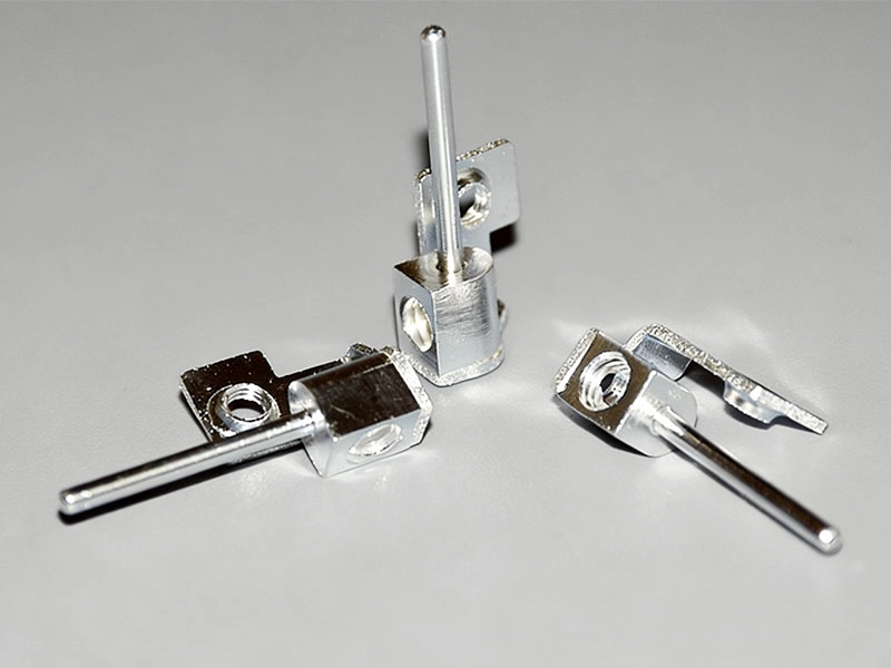
Metode ini paling efektif jika bagian yang dicetak memberikan titik acuan yang berulang dan siklus sekundernya singkat. Metode ini kurang menarik jika distorsi pembentukan membuat pemasangan tidak stabil atau sebagian besar fitur masih memerlukan pengerjaan mesin. A Blok terminal PCB yang dicetak dengan pemesinan sekunder Hal ini menunjukkan prinsipnya: rute yang dipublikasikan menggabungkan pencetakan presisi, pembengkokan, penyadapan, pengeboran, dan pelapisan listrik.


Blok terminal PCB diproduksi melalui proses pencetakan presisi, pembengkokan, pembuatan ulir, pengeboran, dan pemesinan sekunder.

Mengapa Peralatan Stamping Tidak Selalu Menguntungkan

Memperhitungkan Permintaan Sepanjang Masa, Perubahan, dan Operasi Tersembunyi

Siklus hidup produk yang singkat, revisi pelanggan yang sering, atau permintaan yang tidak pasti mungkin tidak mengkonsumsi cukup komponen untuk mengembalikan investasi cetakan. Buatlah model untuk kuantitas masa pakai yang rendah, yang diharapkan, dan yang tinggi, alih-alih mengandalkan satu perkiraan tahunan yang optimis.

Biaya akhir komponen yang dicetak harus mencakup penghilangan gerinda, pembuatan ulir, pemesinan, pembersihan, pelapisan, pengecatan, inspeksi, perakitan, pengemasan, perawatan perkakas, dan kemungkinan modifikasi. Penawaran harga harus menyatakan apakah uji coba, inspeksi sampel, putaran revisi, penajaman, suku cadang, penyimpanan, dan pemeliharaan termasuk di dalamnya. Perubahan setelah pembuatan cetakan dimulai dapat menambah biaya dan penundaan, sehingga pelepasan perkakas formal menjadi kontrol yang penting.

Cara Menghitung Titik Impas Peralatan Stamping

Bandingkan dua jalur manufaktur yang terdefinisi sepenuhnya:

Jumlah titik impas = investasi perkakas ÷ (biaya unit CNC yang selesai − biaya unit stamping yang selesai)

"Penyelesaian" itu penting. Biaya CNC harus mencakup material, pengaturan, pemesinan, perkakas, inspeksi, penyelesaian akhir, dan pengemasan. Biaya stamping harus mencakup desain cetakan, uji coba, produksi mesin pres, pemanfaatan material, perawatan, operasi sekunder, inspeksi, penyelesaian akhir, dan pengemasan.

Jika benda kerja hasil stamping masih memerlukan pengeboran dan ulir CNC, gunakan biaya bagian hibrida jadi, bukan harga mesin press saja. Uji beberapa skenario volume produksi. Perbedaan biaya per unit yang kecil akan menghasilkan periode pengembalian modal yang panjang; perbedaan yang lebih besar dapat membenarkan pengadaan perkakas lebih cepat.

Mintalah setiap penawar untuk memberikan penawaran dengan revisi gambar, material, rentang kuantitas, cakupan inspeksi, finishing, pengemasan, dan ketentuan kepemilikan alat yang sama. Jika tidak, penawaran mungkin mencakup pekerjaan yang berbeda. Jawaban yang tepat untuk pertanyaan “Berapa volume produksi yang membenarkan penggunaan alat stamping?” adalah rentang titik impas spesifik proyek, bukan angka umum di seluruh industri.

Apakah Komponen yang Dibuat dengan Mesin CNC Cocok untuk Pencetakan Logam?

Pertama, tentukan apakah geometri tersebut dapat diproduksi dari lembaran atau gulungan. Pencetakan memotong dan membentuk bahan datar, sedangkan pemesinan menghilangkan material dari benda kerja padat. Bagian yang tebal, fitur tertutup, atau geometri multi-bidang yang kompleks mungkin tidak dapat dikonversi secara langsung.

Pisahkan Fitur yang Dapat Dicap dari Fitur Kritis yang Dikerjakan dengan Mesin.

Mulailah dengan bentuk dasar. Apakah fungsi tersebut dapat menggunakan ketebalan lembaran yang konsisten? Tinjau tekukan, kedalaman tarikan, hubungan lubang ke tepi, daya pegas balik, dan permukaan yang sensitif terhadap gerigi.

Klasifikasikan fitur gambar ke dalam tiga kelompok: cocok untuk pencetakan, memungkinkan setelah perubahan desain atau toleransi, dan masih memerlukan pemesinan. Lubang presisi, ulir dalam, permukaan penyegelan, lokasi bantalan, dan permukaan acuan mungkin tetap menjadi operasi sekunder. Konfirmasikan acuan lokasi, toleransi pemesinan, dan bagaimana variasi pembentukan akan memengaruhi pengaturan akhir. Pemesinan CNC sekunder umumnya digunakan untuk lubang presisi tinggi dan permukaan pemasangan pada komponen yang dicetak.

Cara Beralih dari Prototipe CNC ke Produksi Stamping

Prototipe CNC memvalidasi fungsi, tetapi belum tentu kemampuan pencetakan. Gambarnya mungkin berisi sudut tajam, ketebalan yang bervariasi, atau toleransi ketat yang dibuat berdasarkan proses pemesinan daripada pembentukan.

Tetapkan Persyaratan Tetap, Kemudian Gunakan DFM dan Persetujuan Artikel Pertama

Sebelum melakukan pencetakan presisi, pastikan material, ketebalan, antarmuka, dimensi kritis, finishing, dan revisi gambar. Proyek yang masih mengalami perubahan fungsional atau antarmuka pelanggan harus tetap dalam proses yang fleksibel hingga risiko utama teratasi.

Transisi yang terkontrol mengikuti urutan ini: validasi prototipe, pencetakan DFM, revisi gambar produksi, desain perkakas, uji coba perkakas, inspeksi sampel, koreksi, persetujuan artikel pertama, uji coba produksi, dan rilis produksi. Tinjauan sampel harus mencakup gerinda, retakan, kerutan, pantulan balik, kondisi pelapisan, penampilan, dan kinerja perakitan, bukan hanya dimensi.

Apa yang Harus Disertakan Pembeli dalam Permintaan Penawaran (RFQ) CNC-ke-Stamping

Penawaran harga yang akurat memerlukan gambar 2D dan file STEP terkini, bentuk material dan stok, ketebalan, kuantitas tahunan dan seumur hidup, proses saat ini, toleransi kritis, penyelesaian akhir, pemesinan sekunder, inspeksi, pengemasan, dan perubahan yang diketahui.

Selain itu, bandingkan juga kepemilikan alat, penyimpanan, perawatan, pengasahan, sisipan cadangan, biaya modifikasi, hak transfer, dan penanganan akhir program. Harga cetakan yang rendah dapat menimbulkan biaya di kemudian hari jika perubahan teknik atau dukungan produksi tidak disertakan.

Memilih Pemasok untuk Transisi CNC ke Stamping

Pemasok yang berkualitas harus mengevaluasi kedua jalur tersebut. Verifikasi apakah peralatan dibuat secara internal, apakah tim uji coba dan produksi berbagi tanggung jawab, apakah pekerjaan sekunder dapat dikoordinasikan, dan bagaimana artikel pertama, revisi, keausan peralatan, dan tindakan korektif dikendalikan.

Zhejiang Chuangkai Mechanical and Electrical Technology Co., Ltd., yang juga dikenal sebagai CK Metal Tech, menggabungkan pembuatan perkakas, pencetakan logam, permesinan CNC, perawatan permukaan, inspeksi, dan perakitan dalam satu perusahaan. manufaktur logam presisi terintegrasi Cakupan operasinya luas. Sumber daya yang telah dikonfirmasi meliputi 8 mesin CNC empat sumbu, 18 mesin bubut CNC presisi, dan kemampuan pemesinan tipe Swiss. CK Metal Tech juga memproduksi perkakas progresif, perkakas gambar, dan perkakas gabungan serta memegang sertifikasi IATF 16949. Ini mendukung peninjauan jalur CNC penuh, pencetakan penuh, dan jalur hibrida.

Kesimpulan

Penggunaan perkakas cetak (stamping) akan menguntungkan jika komponen tersebut benar-benar dapat dicetak, desainnya stabil, dan penghematan seumur hidup melebihi biaya perkakas, perawatan, validasi, pemrosesan sekunder, dan risiko revisi. Pemesinan CNC tetap berguna untuk prototipe, perubahan desain, geometri padat, dan fitur presisi. Proses hibrida mungkin merupakan jalur yang paling seimbang ketika bentuk dasar dapat dicetak tetapi antarmuka fungsional masih memerlukan pemesinan.

Untuk tinjauan proyek, siapkan gambar terbaru, file STEP, material, kuantitas target, umur program, dimensi kritis, operasi sekunder, dan persyaratan kualitas. Detail tersebut memungkinkan CK Metal Tech untuk meminta tinjauan DFM CNC-ke-stamping dan membandingkan rute yang layak tanpa memerlukan komitmen peralatan langsung.

Pertanyaan yang Sering Diajukan (FAQ)

Berapa volume produksi yang membuat proses pencetakan logam lebih murah daripada pemesinan CNC?

Tidak ada kuantitas universal. Hitung titik impas dari investasi perkakas aktual dan selisih antara biaya unit CNC dan stamping yang telah selesai, termasuk pemeliharaan, pekerjaan sekunder, penyelesaian akhir, inspeksi, dan risiko perubahan desain.

Bisakah komponen yang diproses dengan mesin CNC langsung diubah menjadi komponen hasil pengepresan logam?

Terkadang, tetapi biasanya tidak tanpa DFM (Design for Manufacturing). Bagian padat, ketebalan variabel, fitur yang dalam, atau toleransi yang ketat mungkin memerlukan desain ulang sebelum pembuatan perkakas dimulai.

Apakah komponen hasil stamping masih memerlukan pemesinan CNC?

Mungkin saja. Ulir, lubang presisi, pemasangan bantalan, permukaan penyegelan, permukaan acuan, atau fitur pemasangan yang rapat dapat memerlukan pengerjaan mesin sekunder, pengeboran, penyadapan, pelebaran lubang, atau penggerindaan.

Bagaimana pembeli dapat mengetahui apakah perkakas stamping akan menguntungkan?

Konfirmasikan kelayakan pencetakan, lalu bandingkan biaya siklus hidup lengkap dalam skenario permintaan rendah, yang diharapkan, dan tinggi. Argumen akan lebih kuat jika desain sudah final dan operasi tersembunyi disertakan dalam kedua penawaran.

Apa saja yang perlu diperiksa saat memilih produsen perkakas stamping?

Memeriksa desain alat internal, dukungan DFM (Design for Manufacturing), uji coba, prosedur artikel pertama, kontrol revisi, pemesinan sekunder, inspeksi, pemeliharaan alat, ketentuan kepemilikan, dan manajemen kualitas produksi.

30th Juli 2026
Rumah
WhatsApp
E-mail
Kontak