







10th September 2026
Sheet Metal Fabrication DFM for OEM Enclosures Preventing Bend Distortion, Fit-Up Gaps and Assembly Rework
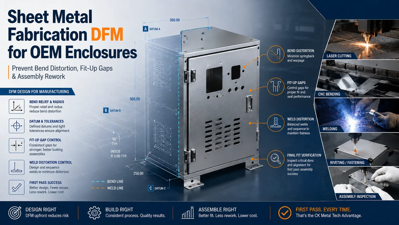
For an OEM enclosure, a drawing can be dimensionally correct and still fail on the assembly line. The usual causes are predictable: bend allowance assumptions that do not match the press brake process, holes placed in unstable bend zones, weld shrinkage that moves a datum, or a tolerance stack-up that leaves visible fit-up gaps. Sheet metal fabrication DFM works when the enclosure is designed around the manufacturing and assembly sequence, not just the flat pattern.
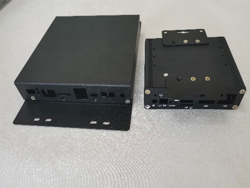
This guide gives engineers and sourcing teams a review path for formed and welded enclosures used in industrial automation, electrical equipment, medical equipment, and OEM products. Material, dimensions, loads, finish, and inspection capability must still be confirmed against the specification.
Why Enclosure DFM Must Start Before the Flat Pattern
An enclosure is a system of interfaces: panels meet at flanges, doors locate against frames, fasteners clamp surfaces, and brackets position electronics. A small flange error can become a large opposite-corner gap. A hole accurate in the flat state can shift after bending, while coating on a grounding or mating surface adds another variable.
Separate functional dimensions from appearance dimensions. Function controls gasket compression, connector alignment, PCB mounting, door closure, rail position, and grounding continuity; appearance controls reveal and visible alignment. Give each group a realistic tolerance and inspection method rather than tightening every edge.
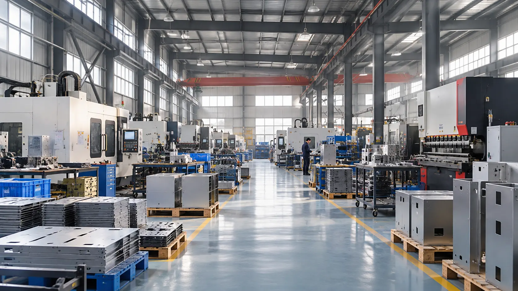
A supplier review is most useful when the design is still flexible. CK Metal Tech lists laser cutting, CNC punching, bending, riveting, welding, grinding, and related operations in its precision sheet metal manufacturing capabilities. That process breadth supports a DFM conversation about sequence, access, fixturing, and inspection before a production route is locked.
Build the Design Around Datums and Bend Behavior
Choose a stable datum scheme
Select primary, secondary, and tertiary datums that can be located repeatedly during cutting, bending, welding, coating, and inspection. Prefer datums accessible after assembly. If a door, lid, or internal rail controls function, reference it from the same scheme used to inspect the body. Avoid dimensioning a critical hole from unrelated outside edges, which hides tolerance accumulation.
Review the flat pattern and formed state together
The flat pattern controls cut features, but the formed state controls fit. Check bend direction, inside radius, flange length, relief geometry, corner notches, and tool access in 3D. Features near a bend may distort, lose perpendicularity, or become hard to reach. Move a hole into a stable flat region, add a relief, or define a secondary operation instead of assuming the nominal location will survive forming.
- Identify dimensions that apply before finishing and dimensions that apply after finishing.
- Call out bend angle, inside radius, and angle tolerance for every functional bend.
- Use reliefs and corner notches to prevent tearing, bulging, and trapped material.
Prevent Bend Distortion Through Process-Aware Geometry
Bend distortion is not solved by laser-cut precision alone. It depends on material grade, thickness, rolling direction, tooling, springback, bend sequence, and material removed near the bend. Ask what the press brake can support consistently and how the part will be located for each hit.
For long panels, distribute bends so the part stays supported and the sequence does not trap the tool. Keep narrow flanges wide enough for the tooling and avoid opposing bends that make the final hit inaccessible. Use formed returns or ribs for a broad face that must stay flat. Confirm bend-table and springback assumptions for stainless steel, carbon steel, aluminum, galvanized, or aluminum-zinc sheet instead of copying another grade.
After first-article bending, inspect squareness, flange distance, hole pattern, panel flatness, and door reveal. Record the process condition; a corrected bend program is more robust than manual rework.
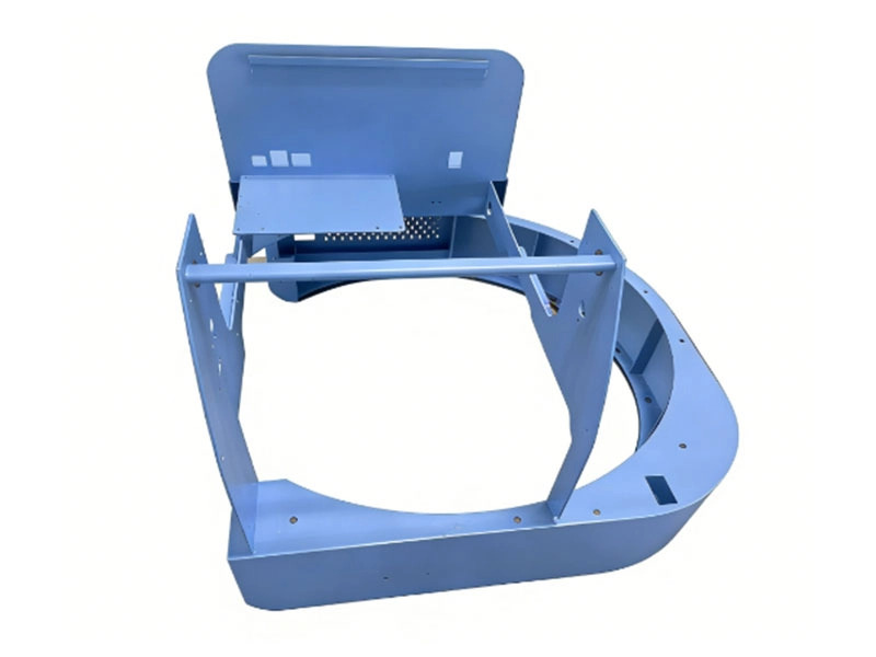
Control Fit-Up Gaps in Welded and Fastened Assemblies
Design the joint for its real purpose
Use welding for structural continuity, sealing, or permanent alignment; use rivets, clinch hardware, or screws where serviceability matters. Each joint changes the tolerance stack-up. Removable panels improve access but add alignment, coating, and grounding variables. Define which surfaces locate the part and which fasteners only clamp it.
Welding introduces heat and shrinkage. Long welds on thin panels can pull a flange out of plane, while an inconsistent gap changes penetration and appearance. Use a fixture tied to functional datums, a balanced sequence, and tack locations that hold geometry. Keep sealing or precision surfaces out of the heat path, or plan a justified post-weld operation.
CK Metal Tech’s published sheet metal scope includes robotic, laser, TIG, and gas-shielded welding for listed steel, stainless steel, and aluminum applications. The correct process remains conditional on thickness, joint design, access, appearance, and required inspection. A supplier should confirm the weld sequence and datum-control plan during the review, not after a fit-up problem appears.
Validate Assembly Before Release to Production
Use a physical prototype to test the interfaces that CAD cannot prove
Prototype validation should include the body, doors, hinges, latches, fasteners, gaskets, brackets, connectors, and representative electronics. Check closure force, screw engagement, door reveal, gasket contact, cable routing, and removal path. A cosmetic sample without real hardware can hide a collision or tolerance stack-up.
- Measure the primary datums and assembly-critical interfaces before coating.
- Repeat the checks after welding, grinding, painting, or powder coating.
- Record the worst-case fit, not only the average sample, and update the drawing or fixture accordingly.
Surface treatment is part of DFM, not a final cosmetic decision. CK Metal Tech offers powder coating and painting routes, including manual lines for large parts and boxes, so the RFQ should identify masked threads, grounding zones, gasket seats, and no-coat surfaces. Coating thickness and surface preparation may vary by material, finish, and configuration; verify the finished assembly where fit or electrical continuity matters.
Make the RFQ Carry the DFM Decisions
A comparable quote needs more than a 3D file. Include the 2D drawing, material and thickness, bend radii and angle tolerances, weld symbols, hardware, finish, masking map, inspection points, quantities, and shipping orientation. State whether alternate bend sequences, reliefs, joint types, or material substitutions may be proposed.
Ask how the supplier will control the features that matter to assembly. Useful questions include: Which datums are used in the bending fixture? How is weld distortion checked? Which dimensions are measured after finishing? How are first-article changes documented? What evidence is provided for a prototype fit check? The OEM/ODM engineering and manufacturing service is relevant when these decisions need to be coordinated across cutting, forming, joining, finishing, and assembly.
A practical supplier scorecard should weight technical communication and corrective-action discipline alongside price. CK Metal Tech describes quality activities including APQP, PPAP, PFMEA, process audits, 5M management, MES, and 8D problem solving. Those systems do not replace part-specific evidence, but they are useful indicators that design changes and nonconformances can be handled through a controlled process.
Conclusion
The most reliable OEM enclosures are designed around the full chain from flat sheet to finished assembly. Establish datums early, keep critical features out of unstable bend zones, plan a balanced weld sequence, and validate the coated assembly with real hardware. When the RFQ records those decisions, a fabricator can quote the same functional requirement the OEM is trying to build. For a project-specific review, contact the technical team with the drawing, material, thickness, quantity, finish, and the interfaces that must fit on the first build.
FAQs
What is the most common DFM cause of enclosure fit-up gaps?
Tolerance stack-up combined with bend-angle variation is a common cause. Weld shrinkage, coating buildup, and locating a feature from the wrong datum can make the gap worse.
Should holes be added before or after bending?
Most holes are cut before bending, but features that require a formed-state relationship may need a secondary operation. The choice depends on access, distortion risk, volume, and the required positional tolerance.
How can a welded enclosure stay square?
Use functional datums in the fixture, controlled tack locations, a balanced weld sequence, and an inspection plan that checks squareness and flange position after welding. Thin sections may need additional support or a different joint strategy.
Does powder coating affect assembly fit?
It can. Threads, gasket seats, grounding zones, and sliding or mating surfaces should be masked or otherwise specified, then checked on the finished part.
What should an OEM send for a DFM review?
Send the latest 2D drawing and 3D model, material and thickness, annual and pilot quantities, finish, critical interfaces, operating environment, assembly hardware, and any fit, sealing, grounding, or inspection requirements.
Leave a reply