







-
1~3일 내 신속한 시제품 제작 및 유연하고 신속한 공급망 이행
-
정시 배송과 일관된 프리미엄 제품 품질에 대한 확고한 약속
-
다양한 소재 옵션과 산업 표준 표면 처리 전반을 제공합니다.
-
공장 직송 견적 및 완전하고 투명한 비용 내역 제공
-
ISO 9001:2015 / IATF 16949:2016 표준에 따라 인증된 품질 시스템
-
턴키 통합 조립 서비스: 당사는 완제품 및 개별 예비 부품을 공급합니다.
시제품 제작부터 대량 생산까지, 맞춤형 금속 가공 서비스를 한 곳에서 제공합니다.
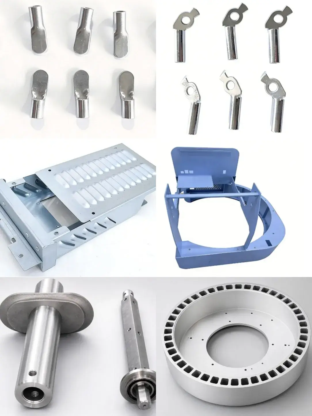
다양한 엔지니어링 및 제조 애플리케이션을 지원합니다.
-
경쟁력 있는 가격 및 DFM
-
연중무휴 24시간 엔지니어링 지원
-
빠른 처리, 짧은 리드 타임, 최소 주문 수량 없음
ISO 9001:2015 | IATF 16949:2016 인증 온디맨드 검증

촹카이에 대하여
저장촹카이 기계전기기술유한공사는 2003년 3월에 설립되었으며, 등록 자본금은 1,500만 위안입니다. 당사는 정밀 공구 설계 및 제조, 정밀 금속 스탬핑, 정밀 판금 가공, 정밀 기계 가공, 표면 도장, 분체 도장 및 정밀 부품 조립을 통합하는 첨단 기술 기업입니다. 현재 95명의 직원을 보유하고 있으며, 약 13,500제곱미터 규모의 첨단 정밀 가공 설비와 표준화된 작업장을 갖추고 있습니다. 당사는 ISO9001, IATF16949, ISO45001, ISO14001 시스템 인증을 획득했습니다.
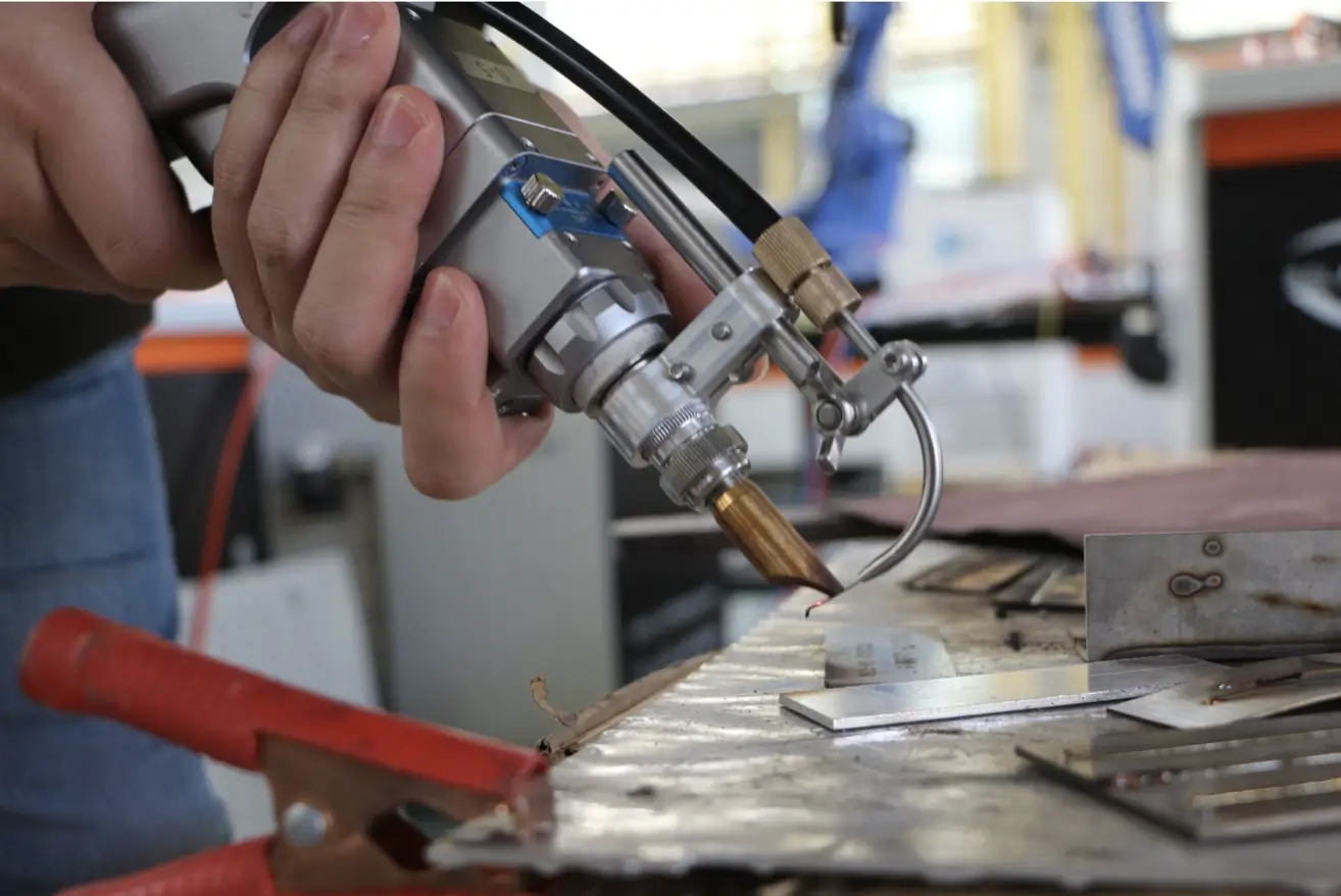
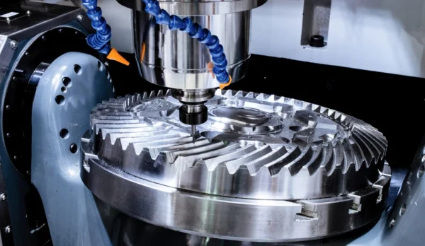
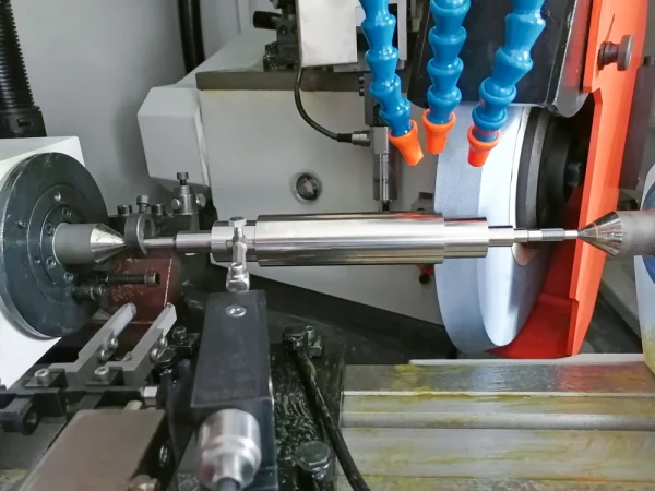

정밀 스탬핑 툴링 설계 및 제조

스탬핑 작업장의 주요 스탬핑 장비는 16톤, 25톤, 40톤, 60톤, 80톤, 110톤, 200톤, 250톤 등의 사양을 갖춘 고속 정밀 펀치 프레스 18세트입니다. 이 고속 정밀 펀치 프레스의 속도는 분당 500회에 달합니다.
스탬핑 가공용 재료: 황동, 인청동, 베릴륨청동, 니켈백동, 각종 강철 및 스테인리스강 재료, 니켈 스트립, 냉간압연강, 강판(도금 포함), 아연도금강판, 저탄소강, 스프링강 및 기타 복합재료.
정밀 판금 제조

판금 작업장은 2대의 대형 첨단 CNC 레이저 절단기, 1대의 CNC 펀칭 프레스, 5대의 CNC 벤딩 머신을 비롯하여 리벳팅기, 용접기, 연삭기, 와이어 드로잉기 등 정밀 판금 가공 장비를 갖추고 있습니다.
이 장비로 가공되는 제품은 산업 자동화, 의료 장비, 전기 장비, 배전함, 배전 접속함 등 다양한 분야에 걸쳐 있습니다. 스테인리스강, 탄소강, 규강, 알루미늄 합금, 아연 도금 강판, 알루미늄-아연 도금 강판 등 다양한 금속 재료에 대해 고속 절단 및 판금 가공과 같은 정밀 가공이 가능합니다.
분체 도장 & 페인팅
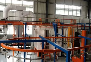
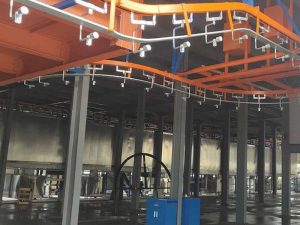
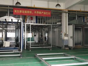
자동 분체 도장 라인 1개;
수동 분체 도장 라인 1개 (대형 부품 및 대형 상자용);
수동 도장 라인 1개 (대형 부품 및 대형 상자용);
자동 분체 도장 및 페인팅 복합 라인 1개가 건설 중입니다.
정밀 가공

가공 작업장은 4축 CNC 기계 6세트, 5축 스위스형 선반 1세트, 정밀 CNC 선반 13세트, CNC 밀링 머신 4세트, 대만 밍양 정밀 자동 선반 16세트, 정밀 일반 선반, 정밀 3축 디지털 디스플레이 밀링 머신, 정밀 벤치 선반, 대만 지쥐안 자동 에지 밀링 머신, 정밀 나사 가공기, 나사 가공 금형, 정밀 탭핑 머신, 정밀 드릴링 머신, 대만 정밀 디지털 디스플레이 밀링 머신, 정밀 칼날 연삭기, 내외측 원통 연삭기, 센터리스 연삭기, 톱질 기계, 초음파 세척 및 건조기, 연마기, 전기 용접기, 아크 용접기 등 다양한 정밀 장비를 갖추고 있습니다.
우리의
소개 영상
재미있는 사실들
더 이상 5개 이상의 공급업체를 조율할 필요가 없습니다. 비용 효율적인 스마트 생산: 수직적 통합과 프로세스 최적화를 통해 분산된 공급망 대비 15~30%의 비용 절감을 실현합니다.
시장 출시 속도: 동시 설계는 리드 타임을 40% 단축합니다. 품질 저하 없이 마감일을 준수하세요.
무료 DFM 분석을 요청하세요: 도면/샘플을 업로드해 주시면, 저희 엔지니어들이 48시간 이내에 비용 및 효율성 최적화 방안을 제시해 드립니다.

회사가 설립되었습니다
0
등록 자본금
0중
직원
0+
공장 지역
0+
우리 사건
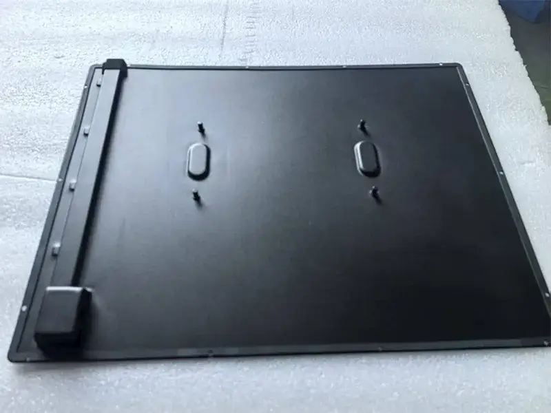
스트레칭 공정을 사용하여 용접+연마+스크래핑 퍼티 기술을 대체하십시오.
용접 및 연마 공정 대신 스트레칭 공정을 사용하십시오. +스크래프 퍼티 기술
기술적 난관을 극복하고 교육 시연 장비용 고품질, 가격 경쟁력 있는 금속 구조 부품을 제작합니다.
고객사가 교육 및 강의용 대형 시연 컴퓨터를 개발하던 중 핵심 금속 구조 부품에서 심각한 문제에 직면했습니다. 초기 설계에서는 돌출부를 용접 방식으로 제작했지만, 제품 테스트 단계에서 용접 불량으로 핵심 테스트를 통과하지 못했습니다. 게다가 용접 비용이 높아 부품 가격이 경쟁사 제품보다 훨씬 높았고, 납기일은 임박하여 고객사는 품질과 비용 측면에서 큰 압박을 받았습니다.
문제점을 정확하게 파악하고 신속하게 대응하여 해결하십시오.
고객의 어려움을 파악한 후, 우리는 신속하게 특별 기술팀을 구성했습니다. 첫 번째 기술 세미나에서 우리는 용접 기밀성 불량의 근본 원인을 심층적으로 분석했습니다. 용접 매개변수 최적화 및 용접기 도입을 통해 기밀성 문제를 해결하고 고객의 초기 품질 요구 사항을 충족했지만, 높은 용접 비용 문제는 여전히 남아 있습니다.
혁신적인 계획, 두 가지 방향으로 진행됨:
기술팀은 여기서 멈추지 않았습니다. 여러 차례의 내부 논의와 고객과의 긴밀한 소통 끝에, 기존 용접 방식을 통합 스탬핑 및 스트레칭 공정으로 대체하는 근본적인 해결책을 제시했습니다. 이 공정은 용접 불량 위험을 근본적으로 제거할 뿐만 아니라 생산 비용을 크게 절감하고 제품이 더 넓은 시장을 확보할 수 있도록 해줍니다.
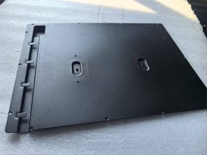
불가능을 움켜쥐고, 약속을 이행하라:
고객 피드백을 바탕으로 스탬핑 및 스트레치 가공 계획을 검토했지만, 다른 공급업체들은 실현 불가능하다고 밝혔습니다. 이러한 질문에 직면했을 때, 우리는 '실행을 통해 배우는 것'이라는 확고한 신념을 가지고 있었습니다. 축적된 기술력을 바탕으로 고객에게 다음과 같은 핵심 최적화 방안을 제시합니다.
재료의 유동성을 최적화하기 위해 인장 경사각을 조정하고, 인장 성능이 우수한 특정 브랜드의 냉간압연 강판을 선택하십시오.
탁월한 결과, 고객들의 찬사:
계획이 확정된 후, 우리는 여러 차례에 걸쳐 엄격한 공정 테스트와 샘플 검증을 실시했습니다. 최종 납품된 부품은 고객의 설계 요구사항과 성능 기준을 완벽하게 충족했습니다. 고객은 결과에 매우 만족하며 "이것은 제가 꿈꿔왔던 완벽한 제품입니다!"라고 극찬했을 뿐만 아니라, 어려운 문제들을 해결해 준 추앙카이 팀의 능력에 진심으로 감사를 표했습니다. 우리는 촉박한 납기 내에 고객을 성공적으로 지원하면서, 까다로운 품질 및 비용 문제를 해결하고 고객 제품이 시장 경쟁에서 우위를 점할 수 있도록 도왔습니다.
교육용 디스플레이 및 시스템을 위한 고품질의 비용 효율적인 금속 부품 제공을 위한 기술적 난관 극복
도전 과제:
훈련 및 교육용 대형 시연 컴퓨터를 개발하던 한 고객사는 핵심 금속 구조 부품에서 심각한 문제에 직면했습니다. 초기 설계에서는 용접 돌출부를 사용했지만, 제품 테스트 중 용접 밀봉 불량으로 인해 고장이 발생했습니다. 설상가상으로 용접 공정 비용이 높아 해당 부품이 경쟁사 제품보다 훨씬 비싸졌습니다. 프로젝트 마감일이 다가오면서 고객사는 품질과 비용 문제를 모두 해결해야 한다는 엄청난 압박에 시달렸습니다.
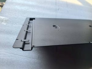
신속 대응 및 초기 해결책:
고객의 어려움을 알게 되자마자, 당사는 즉시 전담 기술팀을 구성했습니다. 초기 기술 검토에서, 당사는 밀봉 불량의 근본 원인을 철저히 분석했습니다. 광범위한 용접 매개변수 최적화 시험과 로봇 용접의 전략적 도입을 통해, 당사는 고객의 품질 사양을 충족하는 데 필요한 밀봉 무결성을 성공적으로 확보했습니다.
근본적인 문제 파악 및 혁신 방안 제시:
당장의 밀봉 문제는 해결되었지만, 제조 비용이 과도하게 높다는 근본적인 문제는 여전히 남아 있었습니다. 타협을 거부하고, 우리 태스크포스팀은 집중적인 내부 브레인스토밍을 진행하는 동시에 고객과 긴밀한 소통을 유지했습니다. 그 결과, 용접 조립 부품을 스탬핑 및 딥 드로잉 방식으로 제작된 일체형 부품으로 대체하는 혁신적인 솔루션을 제안했습니다. 이 접근 방식은 다음과 같은 이점을 약속했습니다.
- 용접 과정에서 발생하는 밀봉 불량의 근본 원인을 제거하십시오.
- 생산 공정을 간소화하여 상당한 비용 절감을 달성하십시오.
- 고객사의 최종 제품에 대한 시장 경쟁력을 강화합니다.
'불가능'을 깨부수다:
고객은 이전에 스탬핑 공정을 검토했지만 다른 공급업체들이 해당 부품에 적용하기에는 불가능하다고 판단했음을 밝혔습니다. '실전에서 증명된다'는 신념에 따라, 당사는 기술 전문성을 활용하여 중요한 설계 최적화 방안을 제안했습니다.
- 1. 재료 흐름을 개선하기 위해 인출 각도를 조정합니다.
- 2. 우수한 심가공성을 지닌 고급 냉간압연강을 지정합니다.
성공적인 결과:
최적화된 설계를 기반으로 엄격한 프로토타입 제작 및 검증 테스트를 거쳐 최종 부품을 납품했습니다. 결과는 탁월했으며, 고객의 설계 의도 및 성능 요구 사항에 완벽하게 부합했습니다. 고객은 깊은 만족감을 표하며 "이것이야말로 제가 설계에서 구상했던 완벽한 제품입니다!"라고 극찬했습니다. 고객은 오랫동안 골머리를 앓았던 기술적 문제를 해결해 준 ChuangKai에 감사를 표했습니다. 저희는 고객이 중요한 마감일을 맞추는 동시에 품질 결함과 비용 장벽을 극복하고 제품의 시장 경쟁력을 크게 향상시킬 수 있도록 지원했습니다.
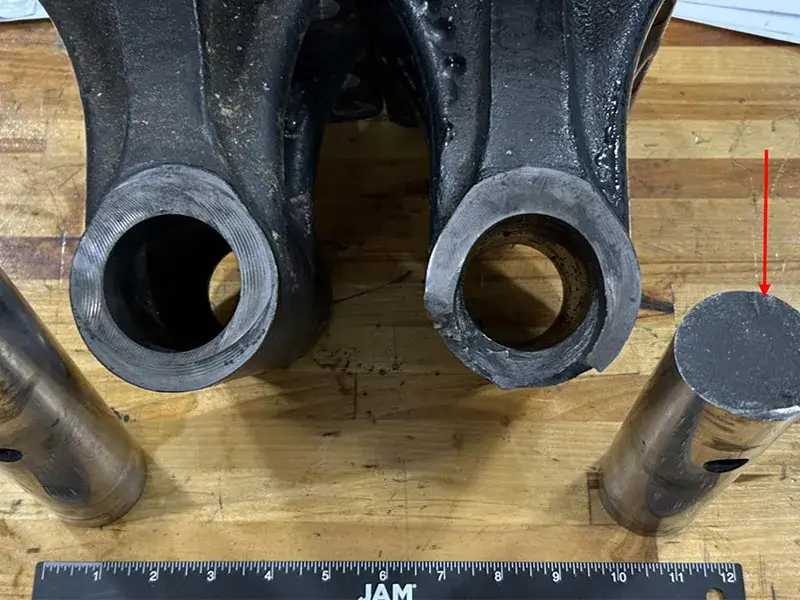
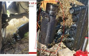
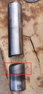
농기계 축 파손 개선 사례 연구
2024년 7월, 한 고객이 작업 중 콤바인 수확기의 축에 파손이 발생했다는 피드백을 보내왔습니다. 이로 인해 수확이 원활하지 못하게 되어 고객은 매우 불안해했습니다. 처음에는 축의 원재료인 40CrNiMoA 또는 열처리 공정의 결함 때문일 가능성을 생각했습니다. 우리는 그들의 도움을 받아 파손된 축을 처음으로 분석한 결과, 원자재나 공정상의 문제가 아니라 고객이 설계한 방식에 문제가 있다는 결론을 내렸습니다. 계절적 요인과 장비의 복잡한 작동 조건을 고려하지 않은 설계, 그리고 일방향 피로로 인한 잠재적 위험, 고객 요구 사항에 따른 전체 고경도 열처리로 인해 중심부 경도가 높아져 피로 파손이 발생하기 쉽다는 점이었습니다. 분석 결과, 기존의 고경도 열처리 대신 전체 품질 조정 및 표면 유도 담금질 공정을 적용하여 중심부 경도는 낮추고 외부 표면 경도는 높여 내마모성을 확보할 것을 제안했습니다. 제안된 공정에 따라 제작된 샘플을 고객에게 발송했고, 두 번째 현장 실험에서 우수한 성능을 보여 긍정적인 피드백을 받았습니다.
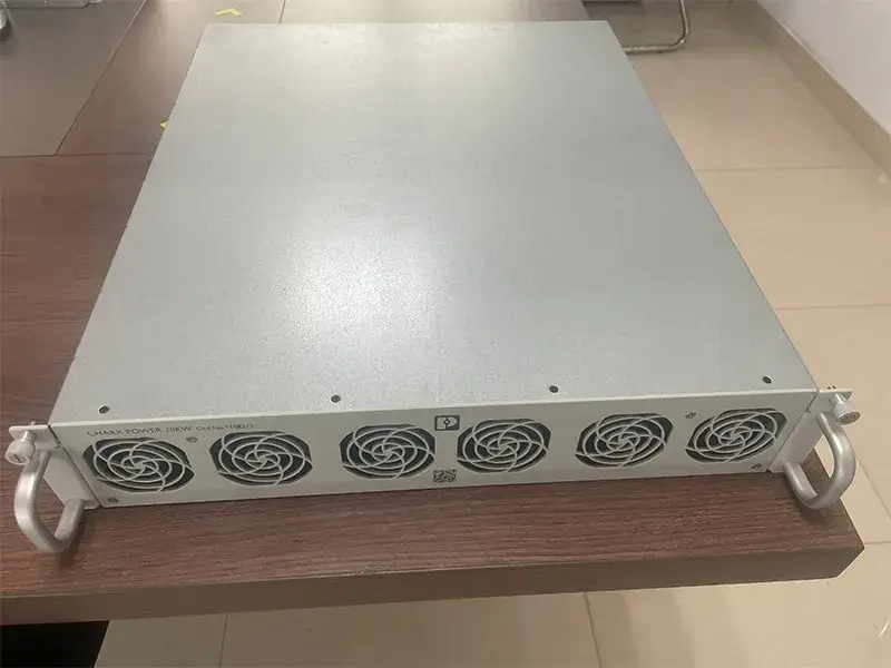
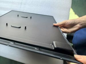
전원 공급 박스 외함 개선 과정
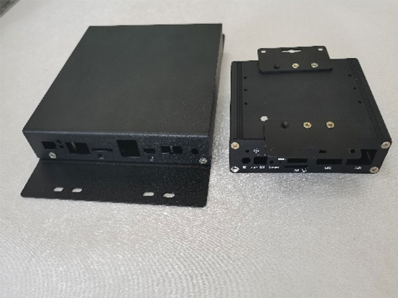
저희 회사의 독일 고객사에서 설계 단계에 어려움을 겪는 조합 박스를 제작하고 계셨습니다. 리벳 접합 방식을 사용하면 박스 표면에서 돌출되어 기능에 영향을 미치고, 용접 방식을 사용하면 외관이 요구 조건을 충족하지 못하고 비용이 많이 드는 문제가 있었습니다. 저희에게 연락하신 후, 다른 프로젝트에서 성공적으로 적용한 사례를 말씀드려, 이중 평머리 리벳과 샐러드 홀을 사용하여 고객사의 문제를 효과적으로 해결할 수 있음을 확인했습니다. 고객사에게 샘플을 보내드렸습니다.
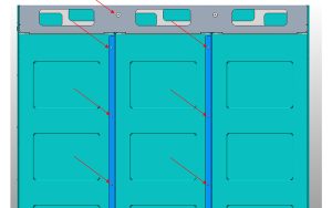
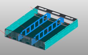
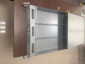
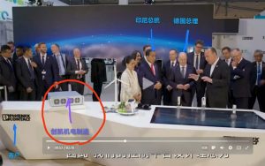
그들은 하노버 전시회에서 매우 만족스러워하며 풍성한 성과를 거두었습니다. 만장일치로 찬사를 받았습니다!

귀사의 엔드투엔드 제조 솔루션 파트너
귀사의 엔드투엔드 제조 솔루션 파트너
기획부터 완성까지 – 글로벌 성공을 위한 정밀 엔지니어링
촹카이는 복잡한 다중 공급업체 소싱 문제를 해결합니다. ODM 및 OEM 솔루션 전문 수직 통합 제조업체로서, 당사는 포괄적인 역량을 통해 고정밀 부품의 원활한 생산을 제공합니다.
통합 제조 서비스:
- 가공 방식: CNC 밀링/선삭, 스위스 머시닝
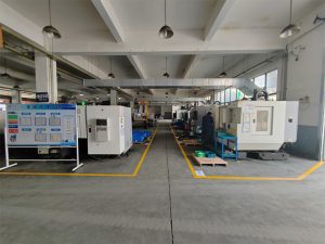
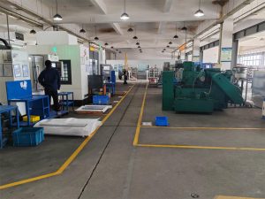
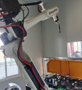
- 금속 가공: 레이저 절단, 벤딩, 용접
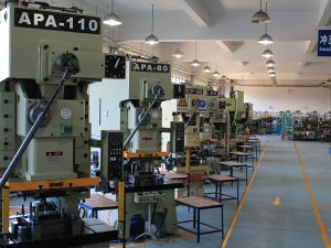
- 스탬핑 및 성형: 프로그레시브 다이 스탬핑, 딥 드로잉
- 툴링 및 성형: 맞춤형 금형 설계 및 제조
- 표면 처리: 분체 도장, 스프레이 도장
- 조립 및 테스트: 전체 키팅, 품질 검증
ODM/OEM이 귀사에 가져다주는 이점:
디자인 혁신
저희 엔지니어링 팀은 고객과 협력하여 제조 용이성, 비용 효율성 및 성능을 최적화하는 설계를 구현하고, 아이디어를 시장 출시 가능한 제품으로 전환합니다.
단일 주체 책임
더 이상 5개 이상의 공급업체를 조율할 필요가 없습니다. 저희가 전체 워크플로우를 한 곳에서 관리해 드립니다.
설계 → 시제품 제작 → 금형 제작 → 원자재 조달 → 생산 → 마감 처리 → 조립 → 물류
비용 효율적인 생산
수직적 통합과 프로세스 최적화를 통해 분산된 공급망 대비 15~30%의 비용 절감을 달성할 수 있습니다.
| 시장 출시 속도 |
동시 설계는 리드 타임을 40% 단축합니다. 품질 저하 없이 마감일을 준수하세요.
| 품질 내장 |
ISO 인증 프로세스와 디지털 추적 시스템을 갖추고 있습니다. PPAP, FAIR, CPK 보고서를 제공합니다.
√ 당사가 서비스를 제공하는 산업 분야:
자동차 | 산업 기계 | 의료 기기 | 신재생 에너지 | 로봇 공학 | 원자력 발전
글로벌 고객들이 저희를 선택하는 이유:
문제 해결 능력: [교육용 시연 장비 사례]처럼 용접 조립품을 일체형 스탬핑 부품으로 교체하여 누출 문제를 해결하고 비용을 25% 절감했습니다.
확장 가능한 용량: 신제품 시제품부터 100만 대 이상의 양산까지 지원합니다.
기술적 민첩성: 20명 이상의 엔지니어가 복잡한 기하공차(GD&T), 엄격한 공차(±0.01mm) 및 재료 관련 문제를 해결할 준비가 되어 있습니다.
→ 무료 DFM 분석을 요청하세요
도면/샘플을 업로드해 주세요. 저희 엔지니어들이 48시간 이내에 비용 및 효율성 최적화 방안을 제시해 드리겠습니다.
제품

자주 묻는 질문
이 섹션에서는 당사의 기계 및 전기 제품, 서비스 및 정책에 대한 일반적인 질문에 대한 답변을 제공합니다. 고객 지원팀에 문의하지 않고도 필요한 정보를 빠르게 찾을 수 있도록 도와드립니다.
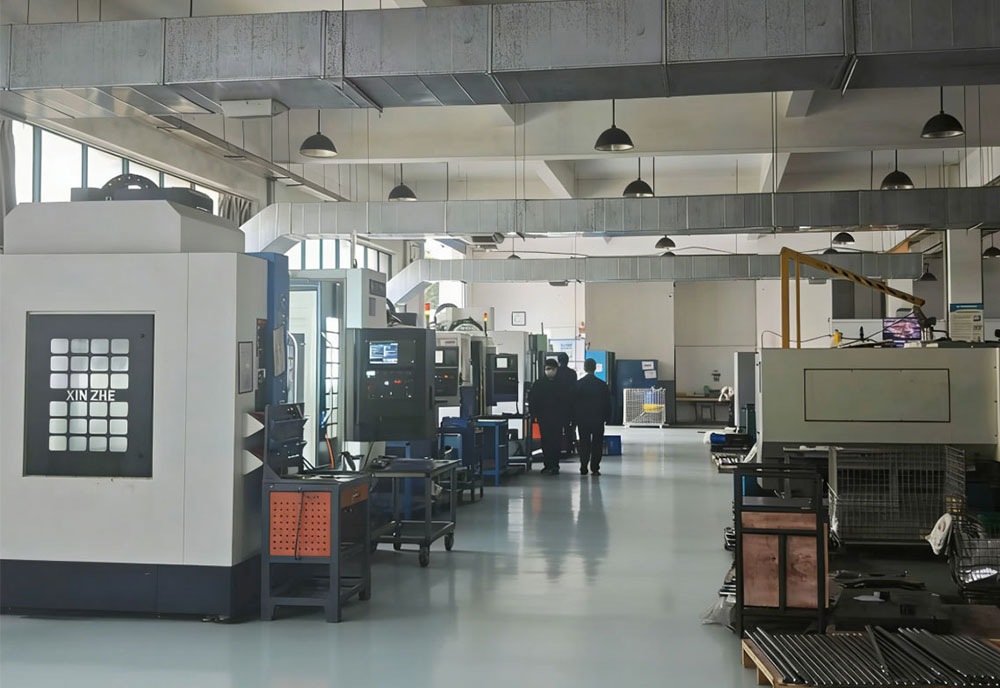
당사의 핵심 역량은 정밀 가공, 정밀 판금 가공, 스탬핑 생산, 위탁 설계 및 제조, 스프레이 도장과 같은 전문적인 표면 처리부터 최종 제품 조립에 이르기까지 전체 산업 체인을 통합하고, 전 과정에 걸쳐 탁월한 품질 관리 시스템을 구현하는 데 있습니다. 이는 고객이 효율적이고 일관성 있는 서비스를 얻기 위해 여러 공급업체와 협력할 필요가 없음을 의미합니다. 모든 단계에서 엄격한 품질 관리를 시행하여 최종적으로 제공되는 제품이 요구 사항을 충족하는 부품이나 제품이 아니라 안정적이고 신뢰할 수 있는 고품질의 종합 솔루션임을 보장합니다. 이를 통해 고객은 납기 단축, 비용 절감 및 공급망 효율성 향상에 효과적으로 기여할 수 있습니다.
맞춤형 비표준 부품 가공. 제품의 복잡성에 따라 달라집니다. 일반적인 납기일은 2~4주입니다.
25
년 경험



















저희에게 연락하세요
최근 기사
최근 기사
기계 및 전기 관련 솔루션이 필요하시거나 문의 사항이 있으신가요? 연락 주세요!
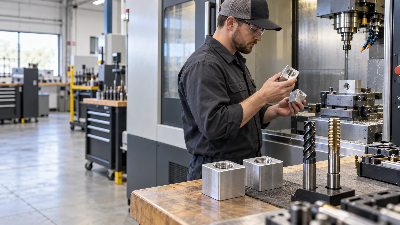
Tapping vs. Thread Milling for CNC-Machined OEM Parts: Choosing the Right Internal Thread Process
23
10월
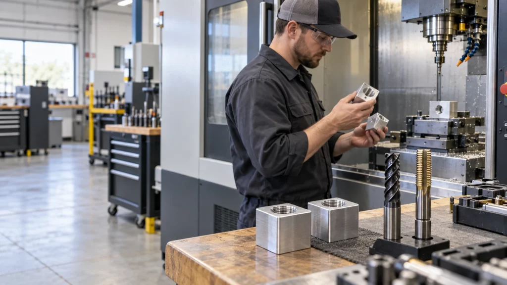
The choice between tapping and thread milling depends on the hole, material, thread specification, production quantity, machine capability, and cost of failure. Tapping is usually the faster route for repeat production of standard internal threads. Thread milling offers more control over thread size and fit, handles a wider range of diameters with fewer tools, and can reduce the consequence of a tool failure in a valuable part.
Neither process is universally better. A through-hole in a stable aluminum part may favor tapping, while a large thread, difficult material, expensive near-finished component, or close fit adjustment may justify thread milling. Blind-hole geometry and usable thread depth can change the answer again.
Tapping vs Thread Milling at a Glance
| Decision factor | Tapping | Thread milling |
| Cycle time | Often faster for standard repeated threads. | Usually longer because the tool follows a helical path. |
| Tool flexibility | One tap normally matches a specific size, pitch, and form. | One cutter may cover multiple diameters that share a compatible pitch and profile. |
| Fit adjustment | Limited after the tap and hole preparation are selected. | Tool-path offsets can adjust the finished thread within process limits. |
| Failure risk | A broken tap may be difficult to remove from the part. | A smaller cutter may be easier to recover from, but breakage can still damage the feature. |
| Machine need | Requires controlled feed and rotation appropriate to the tapping method. | Requires CNC helical interpolation, suitable control, rigidity, and access. |
How Each Process Cuts an Internal Thread
Both methods begin with a prepared hole, but their tool engagement is different. The drawing must specify the finished thread; the process planner then selects the pre-hole, tool, cutting data, and inspection route.
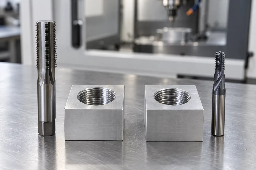
Tapping
A tap advances axially while its cutting edges or forming lobes create the complete thread profile. Because the tool engages around the circumference, torque, alignment, lubrication, chip control, and the prepared-hole diameter are important. Cut taps generate chips. Form taps displace suitable ductile material without chips, but they require a different hole size and should be approved for the material and specification.
Thread Milling
A thread mill rotates while the CNC moves it along a helical path. The cutter is smaller than the finished thread, so it engages a portion of the circumference at a time. The program controls diameter and direction, and suitable cutters can produce internal or external threads. The method needs enough bore access, tool clearance, machine interpolation, and stable workholding.
Choose by Hole Geometry
Through Holes
Through holes usually provide easier chip evacuation and fewer bottom-clearance constraints. For standard sizes and meaningful batch quantities, tapping often provides the most efficient cycle. A spiral-point cutting tap may push chips ahead through the opening when the material and application permit. Thread milling remains useful for large diameters, adjustable fits, mixed thread sizes, or parts where tool-breakage recovery influences the risk calculation.
Blind Holes
Blind holes need separate values for drilled depth, full thread depth, usable engagement, and bottom clearance. A tap has an incomplete lead before it produces full threads, and chips must have somewhere to go. Tap style, coolant delivery, chip evacuation, and reversal therefore matter. Thread milling can approach a shoulder with controlled axial positioning, but it still needs entry and exit clearance and cannot create usable thread beyond its programmed geometry. Do not specify “thread to bottom” without defining a manufacturable termination.
Choose by Material and Thread Specification
Material behavior affects torque, chips, tool wear, heat, and edge quality. Standard threads in machinable aluminum may favor tapping for speed, although chip packing or built-up edge still needs control. Tough stainless steels, high-temperature alloys, or expensive heat-treated parts may make the lower engagement and recovery advantages of thread milling more attractive. The supplier should confirm the exact alloy, hardness, and hole depth before choosing the route.
Thread size and form matter as much as material. Small standard threads may suit tapping, while larger diameters, special profiles, right- and left-hand variants, or adjustable fit classes can favor thread milling. A thread mill is not universal: its diameter, pitch capability, length, cutting form, and reach must match the feature.
Choose by Quantity and Cost of Failure
For a stable high-volume job, the shorter cycle of tapping can outweigh its lower flexibility. For prototypes and mixed families, thread milling may reduce the number of dedicated tools and allow diameter correction through offsets. The value of the workpiece also matters. Breaking a tap in an almost-complete housing can cost more than the saved cycle time; however, thread milling adds programming time and may use a more expensive cutter. Compare total route cost, not tool price alone.
Define the Thread Correctly on the Drawing
A process comparison cannot correct an incomplete specification. Use the same feature-based discipline applied to CNC machining tolerances, and include the following information:
- Thread standard and designation, nominal size, pitch or threads per inch, internal class or tolerance, and right- or left-hand direction.
- Through or blind condition, drilled depth, full thread depth, minimum usable engagement, entrance chamfer, and any bottom-clearance limit.
- Material grade and condition, heat treatment, coating or plating, quantity, critical datum relationships, and mating-fastener information.
- Inspection method, gauge standard, sampling level, first-article record, and any functional assembly test.
A complete CNC machining RFQ checklist also keeps model, drawing, revision, finish, and inspection assumptions consistent across bidders.
Verify the Sample and Production Route
Inspect the pre-hole as well as the finished thread. Confirm location, diameter, depth, chamfer, burr condition, and cleanliness. Use the specified GO and NO-GO gauges or another agreed method, then test the real mating fastener when assembly behavior matters. Record tool offsets and wear limits for thread milling, or torque, tap life, and chip-control checks for tapping. A first article should also confirm that coating, plating, or heat treatment does not invalidate the final fit.
Evaluate Supplier Capability Against the Part
CK Metal Tech publishes precision machining capabilities that include CNC milling, drilling, tapping, and related inspection resources. Its broader CNC machining services for precision metal parts provide the context for OEM process planning. The project review should still confirm whether tapping, thread milling, or another threading method is available and appropriate for the specific size, material, depth, tolerance, quantity, and inspection plan.
결론
Use tapping when a standard internal thread, suitable material, controlled hole, and repeat quantity make cycle time the priority. Consider thread milling when fit adjustment, large or varied sizes, difficult materials, blind-hole constraints, or the cost of a trapped broken tap changes the economics. The drawing and sample plan should make the choice verifiable rather than leaving it to habit.
자주 묻는 질문
Is Thread Milling Always More Accurate Than Tapping
No. Either process can make acceptable threads when the machine, tool, hole preparation, setup, and inspection suit the requirement. Thread milling offers useful diameter adjustment, but it does not replace process control.
Which Process Is Better for Blind Holes
It depends on usable depth, bottom clearance, material, chip control, thread size, and quantity. A suitable tap can be efficient; thread milling can improve control where evacuation or failure consequences are difficult.
Can One Thread Mill Cut Several Thread Sizes
Sometimes. A cutter may cover multiple diameters with a compatible pitch and profile, within its diameter and reach limits. Confirm the tool manufacturer’s range and the required thread form.
How Should an Internal Thread Be Inspected
Use the drawing’s specified gauge or measurement method and sampling plan. GO and NO-GO gauges are common, but depth, location, surface condition, and functional assembly may also require verification.
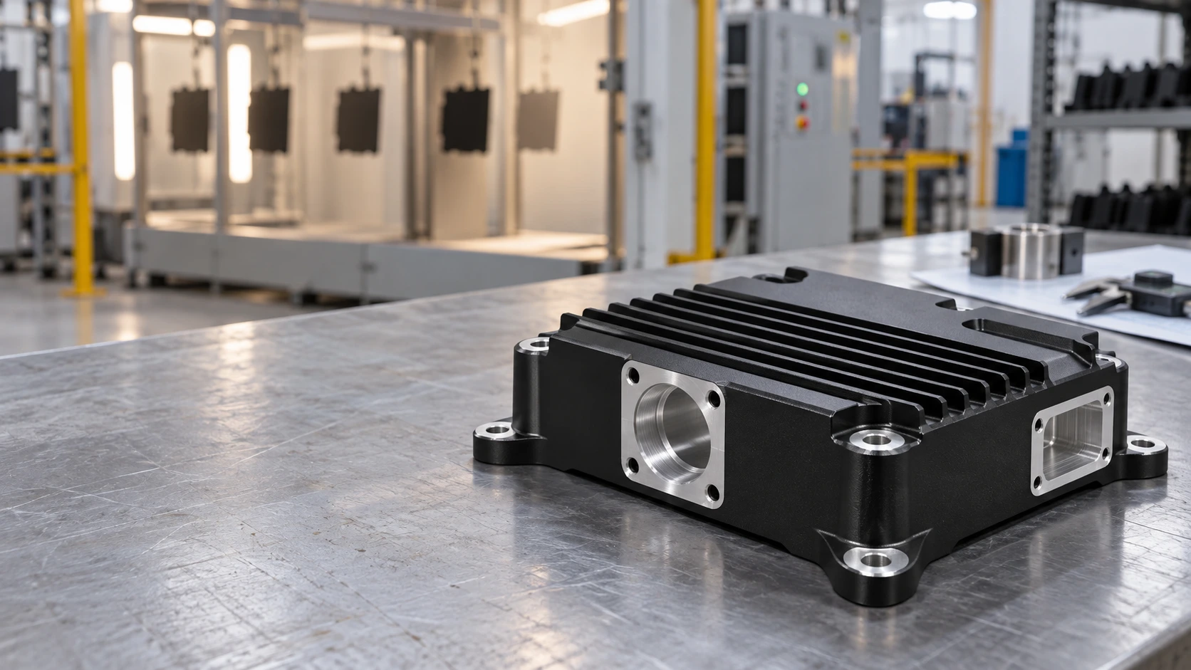
Can CNC-Machined Aluminum Housings Be Powder Coated? Thermal Interfaces, Fits, and Masking
22
10월
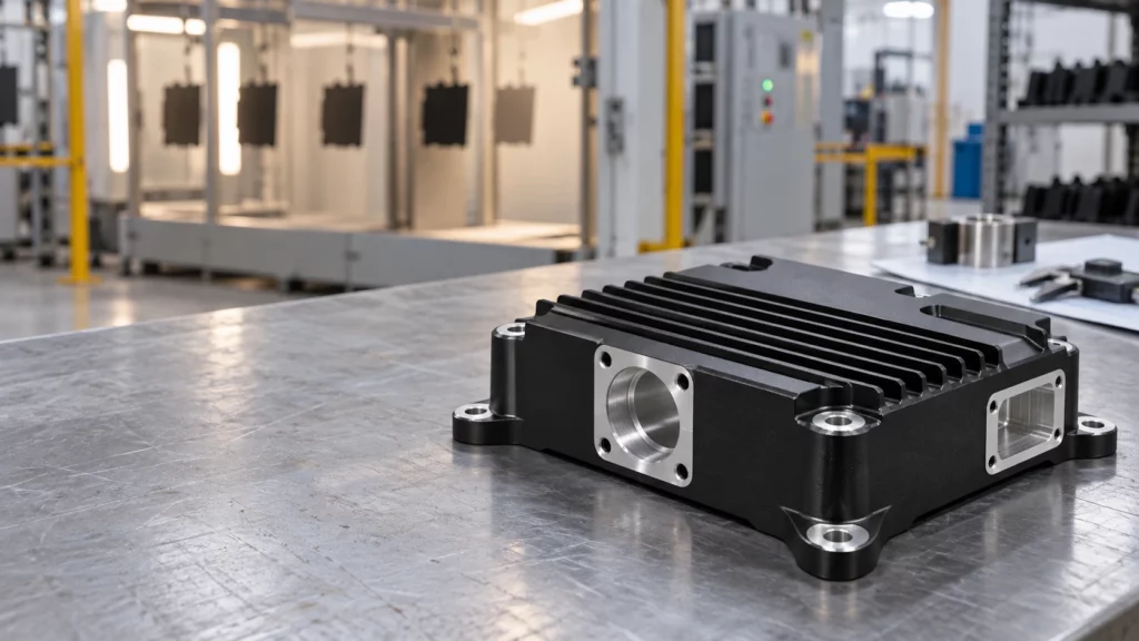
Can aluminum be powder coated after CNC machining? Yes, provided the drawing distinguishes cosmetic or protective surfaces from interfaces that must remain dimensionally, electrically, or thermally functional. A coating that performs well on an exterior wall can cause interference in a close fit, obstruct a thread, insulate a bonding point, or add thermal resistance at a heat-transfer joint.
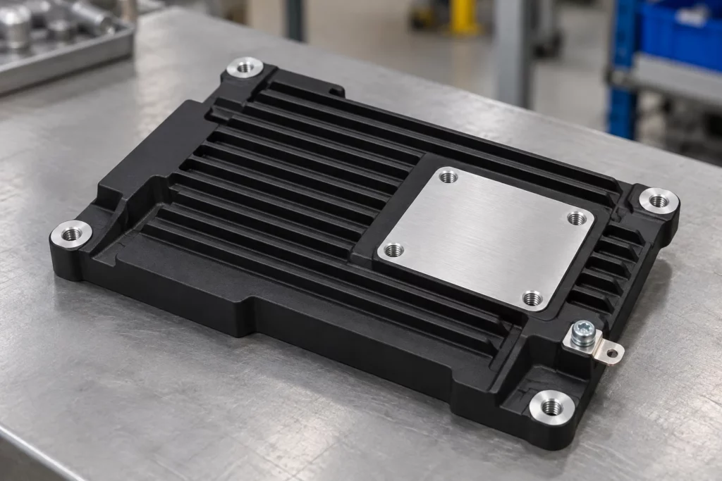
The review should therefore start with the finished assembly, not the color. CK Metal Tech’s aluminum alloy cooling and shielding cover plate illustrates why this distinction matters: one machined component may combine an exterior cover, mounting holes, grooves, structural bosses, shielding functions, and heat-dissipation duties. Those surfaces should not automatically receive the same finish treatment.
Map Functional Surfaces Before Coating
Create a finish map on the controlled drawing or model. Identify coated faces, cosmetic faces, no-coat zones, and surfaces whose final dimensions apply after finishing. A generic note such as “powder coat black” does not tell the manufacturer how the housing must assemble or perform.
Surfaces Commonly Suitable for Coating
Exterior walls, non-mating covers, guards, and handling surfaces are typical candidates when the selected pretreatment and powder system match the aluminum alloy and service environment. Coating can support appearance and surface protection, but corrosion, chemical exposure, ultraviolet exposure, and cleaning requirements still need project-specific confirmation.
Surfaces That Often Need Masking
Common no-coat candidates include bearing or bushing seats, locating datums, close-tolerance bores, sliding rails, O-ring lands, sealing faces, connector grounds, threaded holes, fastener seats, and direct thermal contact pads. The decision is functional rather than categorical: a clearance hole may tolerate film build, while a locating hole with the same nominal diameter may not.
Mask Boundaries Need Their Own Definition
A no-coat note should show where the boundary begins, which direction the mask may shift, and whether a small transition band is acceptable. This is important around countersinks, spotfaces, grooves, stepped bores, gasket lands, and thermal pads. Masking has practical placement variation, and the cured edge may not form a perfectly sharp geometric line. Keep the boundary away from a sealing path or precision datum where possible. If the transition itself affects function, dimension it from a stable feature and include it in the first-article inspection plan.
How Powder Coat Changes Functional Interfaces
Powder coating adds material to the surfaces it covers. The actual build depends on the powder, application, grounding, part geometry, racking, and cure route, so the drawing should define the finished requirement instead of assuming a universal allowance.
| Feature | Coating risk | Drawing or process control |
| Fits and threads | Film build reduces clearance and can obstruct engagement. | Mask, allow for the finish, or approve controlled post-coat machining. |
| Grounding points | The organic film can interrupt metal-to-metal electrical contact. | Mark bonding pads and define continuity or resistance verification. |
| Thermal interfaces | The coating and any trapped air can add resistance at a contact joint. | Keep direct-contact pads bare when required and define flatness, pressure, and interface material. |
| Sealing and datums | Build-up or an uneven mask edge can change seating and measurement references. | State whether dimensions apply before or after coating and locate mask boundaries. |
Fits and Threaded Features
Check each fit against its mating component and the finished-state tolerance. The same feature-level reasoning used for CNC machining tolerances applies after coating. Thread masks must protect the required diameter, lead-in, and usable depth. Forcing a screw through cured powder is not a controlled acceptance method because it can damage the finish and leave debris in the assembly.
Grounding and Thermal Contact
A designated grounding pad needs a clean boundary, a suitable fastener interface, and a defined verification method. Bare aluminum may also need a compatible protection strategy that preserves conductivity. For heat-transfer pads, evaluate coating together with contact area, surface flatness, clamping pressure, and any thermal interface material. A sample should be tested under representative heat load when temperature performance is critical.
Coordinate CNC Machining and Powder Coating as One Route
The safest sequence is established before chips are cut. Treat masking, finishing, and final inspection as part of the manufacturing plan rather than instructions added after machining.
- Review the current drawing, aluminum grade or approved alternative, functional interfaces, cosmetic zones, and operating environment.
- Machine the housing with any agreed allowance for surfaces controlled in the finished state; deburr edges without altering critical geometry.
- Clean and pretreat the part using a route compatible with the alloy, contamination condition, and specified coating system.
- Install plugs, caps, or high-temperature masking at the defined boundaries, then verify mask seating before spraying.
- Apply and cure the coating, remove masks cleanly, and inspect boundaries for lifting, chips, or unintended coverage.
- Complete only approved secondary machining or thread restoration, then clean the part and protect newly exposed aluminum as required.
An integrated review can connect the company’s precision machining capabilities with its powder coating service. The exact masking materials, post-coat operations, and inspection methods should still be confirmed for the part.
Verify the First Article Before Production
A first article should prove more than color and appearance. Use the actual mating components or representative gauges where possible, and record the drawing revision and coating specification used for approval.
- Dimensions: measure critical fits, datums, hole locations, and flatness in the state specified on the drawing.
- Assembly: install fasteners, covers, seals, rails, connectors, and locating features without forcing or finish damage.
- Electrical function: verify required bonding or shielding continuity at the specified contact points.
- Thermal function: check temperature performance under a representative load when the housing forms part of the heat path.
- Finish: inspect coverage, cure evidence, mask edges, handling damage, and cosmetic acceptance against an agreed reference.
Record nonconforming features separately. A part should not pass because its exterior looks uniform when a thread, bonding pad, thermal interface, or locating surface fails its own requirement.
What to Put in the Drawing and RFQ
Submit the 2D drawing and 3D model with material, quantity, coating system or performance requirement, color and texture, finished-state dimensions, no-coat zones, mask depth, thread callouts, grounding locations, thermal pads, inspection records, mating-part information, and sample approval criteria. Separate prototype quantity from expected production volume so the supplier can evaluate masking fixtures and process controls appropriately.
결론
CNC-machined aluminum housings can be powder coated successfully when the finish map protects the part’s working interfaces. The design should preserve required clearance, thread engagement, electrical bonding, and thermal contact, while the process plan should connect machining, pretreatment, masking, coating, and finished-state inspection.
자주 묻는 질문
Should Every Threaded Hole Be Masked
No. Masking depends on thread function, fastener fit, engagement depth, and the approved finishing route. The drawing should identify which threads must remain coating-free and how they will be checked.
Can Powder Coat Be Allowed for in a Close Fit
Sometimes, but the designer and manufacturer must agree on the final clearance and whether the controlling dimension applies before or after coating. Do not rely on a generic film allowance.
Should a Thermal Contact Pad Remain Bare
Often it should when direct metal contact is part of the heat path. Confirm the complete joint, including flatness, contact pressure, interface material, corrosion protection, and the required thermal test.
Is Post Coating Machining Acceptable
It may be, if the operation is planned. Control chips, protect the surrounding finish, re-inspect dimensions, and define how newly exposed aluminum will be handled.
Request a Joint Machining and Coating Review
Send CK Metal Tech the drawing revision, alloy, quantity, mating-part details, coating requirements, no-coat zones, thermal duty, grounding needs, and inspection expectations. Use the request a joint machining and coating review route to confirm the manufacturing sequence before quotation.
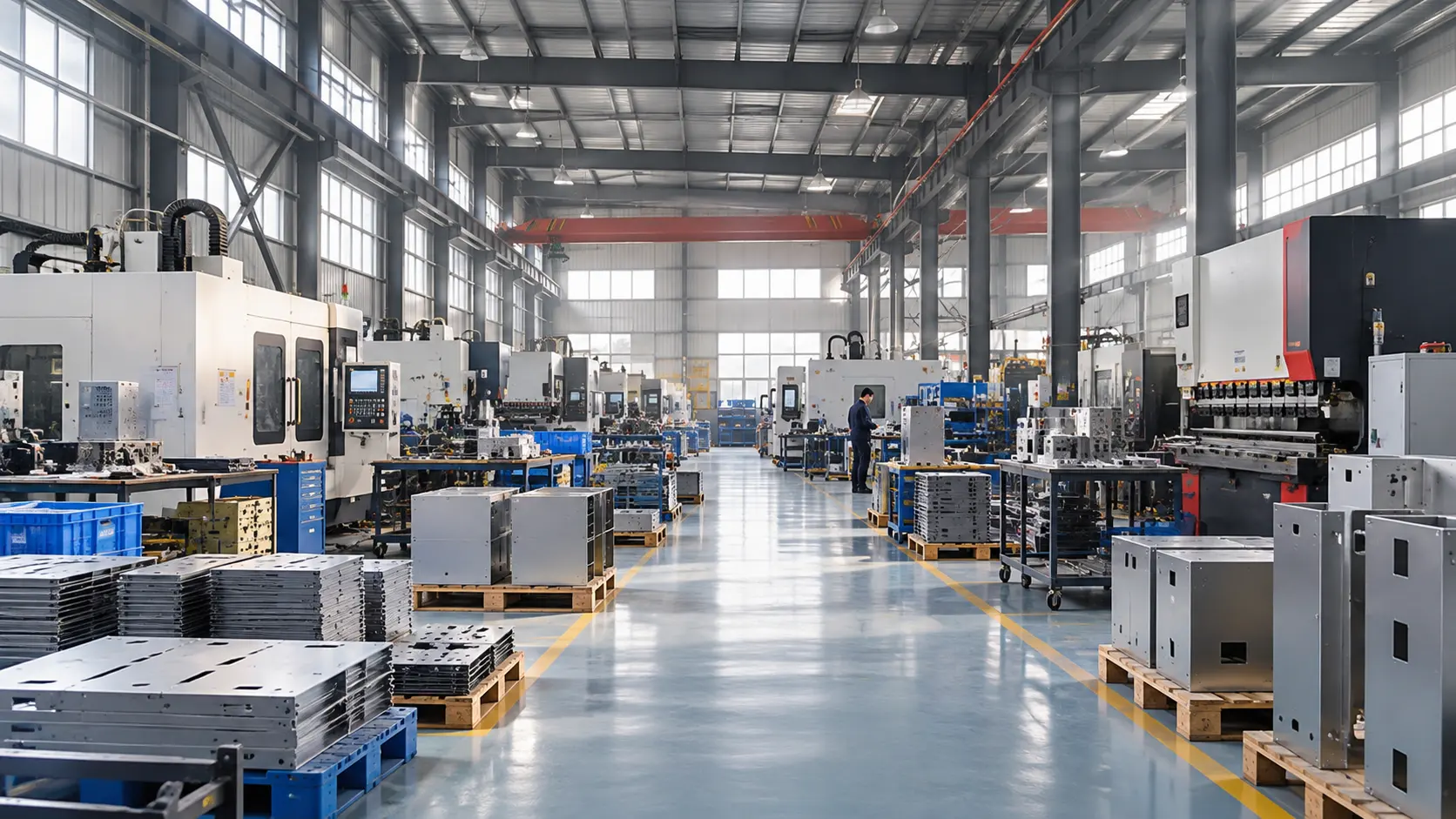
One Metal Supplier vs Multiple Vendors: How to Calculate Total Landed Cost
16
10월
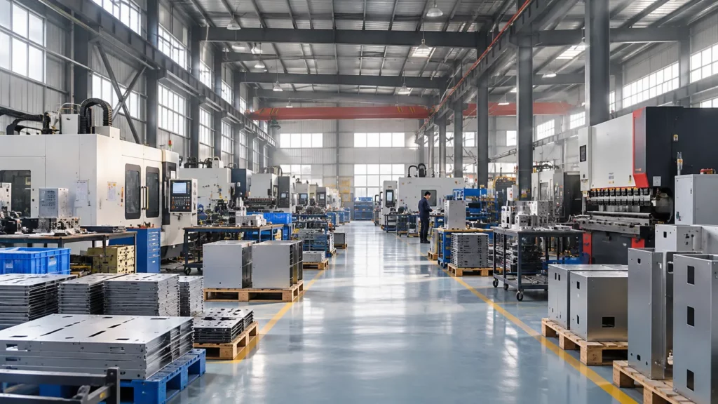
One metal supplier can reduce transfers between fabrication, finishing, and assembly, but supplier consolidation does not automatically lower total landed cost. Compare both routes at the same delivery destination, then add the buyer-side costs needed to turn delivered parts into accepted assemblies. Keep those layers separate: shipping and import charges belong in the landed-cost calculation; supplier administration, inventory, and integration costs belong in the broader sourcing decision.
For an OEM buying custom metal parts, this distinction prevents a lower piece price from hiding extra work. It also avoids calling every future operating expense a landed cost.
Define the Deliverable Before Comparing Vendors
Start with one controlled bill of materials and drawing revision. Specify material, finish, quantity, inspection criteria, packaging, destination, and assembly responsibility. A coated panel from one vendor cannot be compared directly with an assembled enclosure from another unless the missing operations are priced separately.
Distinguish process splitting from dual sourcing. Sending cutting to one shop and coating to another creates sequential handoffs. Qualifying two independent suppliers for the same finished assembly creates a backup route. These arrangements have different costs and continuity benefits; combining them under “multiple vendors” obscures the decision.
Calculate Total Landed Cost in Two Layers
The core shipment calculation is:
Landed cost = supplier invoices + separately charged tooling + packaging + freight + insurance + applicable duties, taxes, and clearance fees.
The International Trade Administration’s landed-cost guidance supports the product-plus-delivery approach. For metal parts, verify which charges are already included in each quotation. Add only costs outside the quoted scope, and use the same receiving location.
Then calculate a separate management metric:
Sourcing comparison cost = landed cost + buyer assembly and inspection + supplier administration + inventory carrying cost + evidence-based quality and disruption allowances.
This second formula is a purchasing decision tool, not a customs valuation or accounting rule. It does not include equipment operating costs over the product’s lifetime. Keep recoverable taxes and other accounting treatments identifiable for finance review rather than treating every cash payment as a permanent expense.
Normalize Quotes and Allocate Shared Charges
Use the same currency, demand period, release size, and named delivery point. Record the delivery term and which party pays each freight leg. A quote that includes shipping can appear expensive beside a factory-gate quote until the missing freight is added.
For international purchases, ask a qualified broker to verify classification, origin, applicable charges, and the relevant shipment date. Do not copy a tariff percentage from another part or last year’s order.
Allocate shared freight across a mixed shipment using a defensible driver, such as chargeable weight or occupied volume. Allocate tooling over the realistically committed program quantity, with tooling ownership shown separately. Show first-order and repeat-order costs independently; an optimistic lifetime volume can conceal a costly launch.
A Worked Example for One Thousand Assemblies
The following figures are hypothetical USD amounts, not CK Metal Tech quotations or tariff estimates. Both routes ultimately provide 1,000 accepted assemblies. The single supplier includes assembly in its invoice; the split route requires more buyer assembly work. Charges already included in supplier invoices are excluded from the other rows.
| Cost category | One supplier | Multiple vendors |
| Supplier invoices | $40,000 | $37,000 |
| Tooling and setup | $3,000 | $2,200 |
| Packaging freight and insurance | $1,800 | $3,300 |
| Illustrative import and clearance charges | $1,500 | $1,500 |
| Core landed cost | $46,300 | $44,000 |
| Buyer assembly and inspection | $800 | $3,300 |
| Supplier administration | $400 | $1,200 |
| Inventory carrying cost | $600 | $1,100 |
| Expected quality and rework allowance | $600 | $1,800 |
| Sourcing comparison total | $48,700 | $51,400 |
| Cost per accepted assembly | $48.70 | $51.40 |
Multiple vendors win the core landed-cost comparison by $2,300. After buyer-side costs are included, one supplier is lower by $2,700. This result follows the stated assumptions; it does not prove that consolidation is generally cheaper.
The decision changes if the split route reduces internal assembly effort, avoids quality losses, or provides a valuable qualified backup. Replace every allowance with program evidence before using this example for an award decision.
Measure Handoffs Without Double Counting
Map the route from cutting and forming through machining, coating, final inspection, and packing. Sheet metal fabrication may involve several linked operations, so track the transfers between them rather than counting suppliers alone.
For each handoff, record transport, protective packaging, receiving inspection, queue time, and revision-control responsibility. Estimate internal work from hours multiplied by an approved labor rate. Distinguish cash savings from staff capacity released: fewer purchase orders do not necessarily reduce payroll.
Estimate inventory carrying cost from average inventory value, the approved annual carrying rate, and the time period. Use historical rework and expedite costs where available. For a new program, show low, expected, and high cases rather than inventing a precise failure probability.
Avoid charging the same loss twice. If rejected units already reduce the accepted-unit denominator, check whether a separate scrap allowance repeats that loss. Likewise, do not add replacement freight when it is already included in a rework estimate.
Choose the Route and Test Its Weak Points
One supplier is attractive when interfaces dominate the program: welded frames must match machined brackets, coating boundaries affect fit, and completed assemblies require a coordinated release. Multiple vendors may be preferable when a process needs specialist qualification, capacity is constrained, or a genuinely independent backup is essential.
A backup is only useful if drawings, tooling access, qualification status, and available capacity make it executable. Two suppliers sharing the same critical subcontractor may still have a common interruption risk. Keep continuity requirements visible beside the cost comparison.
Test the decision against smaller releases, a rejected batch, an engineering change, and an expedited shipment. If the winner changes under a small assumption adjustment, resolve that uncertainty before committing the production route.
Request a Comparable Metal Manufacturing Quote
CK Metal Tech combines sheet metal processing, machining, stamping, powder coating, painting, and precision-component assembly. Review its metal manufacturing and assembly capabilities against the proposed route; process breadth alone does not establish capacity or suitability for a particular program.
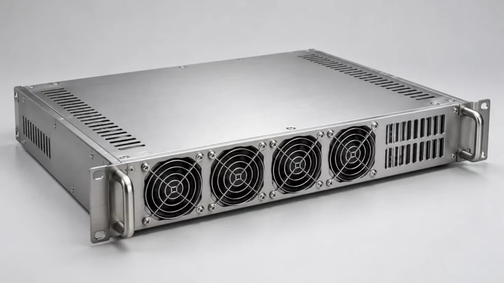
Send the BOM, controlled drawings, quantities, destination, finish requirements, and acceptance plan. Ask CK Metal Tech to separate tooling from recurring prices and identify subcontracted operations, excluded services, and packing assumptions. Give alternative vendors the same package.
결론
Choose the sourcing route using both delivered cost and the work required to obtain accepted assemblies. A transparent comparison can show that multiple vendors win on landed cost while one supplier wins after integration costs, or the reverse. Award the route whose cost assumptions and continuity requirements can be verified.
자주 묻는 질문
Is one metal supplier always cheaper
No. Consolidation may reduce transfers and administration, while multiple vendors can provide specialist capability or backup capacity. Compare equivalent outputs and documented costs.
Is total landed cost the same as total cost of ownership
No. Landed cost addresses acquisition and delivery. Ownership cost extends into use, maintenance, and disposal. Buyer integration costs should remain a clearly labeled comparison layer.
How should tooling be included
Show the initial tooling payment separately, then allocate it across a defensible committed quantity for the unit comparison. Record ownership, maintenance responsibility, and repeat-order assumptions.
Should supplier management time count as a saving
Include it when comparing resource demand, but distinguish released staff capacity from actual cash savings. Use measured hours and an approved rate.
Request a Sourcing Route Review
Share the current drawings, BOM, delivery location, release schedule, and assembly scope with CK Metal Tech. Request a sourcing-route review to clarify included operations and compare the assumptions behind each quotation.