







25th September 2026
Tooling DFM for Metal Stamping: Prevent Die Rework
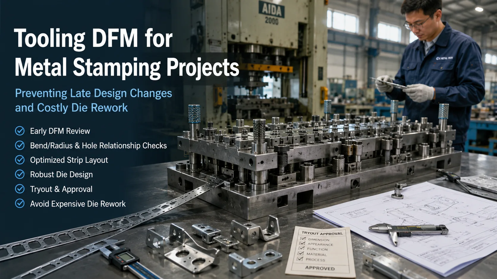
Tooling DFM (design for manufacturing) connects a stamped-part drawing to a workable die, press route, material, and inspection plan before steel is cut. Its value is highest before tool release, when a change to a bend, hole, radius, or strip layout is still a drawing edit rather than die rework. The goal is to freeze the right requirements early and expose risks while they remain inexpensive to correct.
A disciplined review asks: Can the geometry be formed from the selected stock? Can the die support tolerance and tool-life needs? Can the finished part be inspected and assembled? What happens if the design changes after tooling starts? These answers create a gate between prototype approval and production tooling.
What Tooling DFM Should Confirm Before Die Design
Start with function, stock form, and production intent
Begin with the part’s job, not just its current CAD shape. Identify load paths, contact surfaces, spring features, sealing edges, electrical interfaces, and cosmetic faces. Then confirm material grade, temper, thickness, coil or blank form, grain direction where relevant, and expected annual and lifetime quantities. A part designed around CNC machining may contain solid sections, sharp internal corners, or tolerances that are unsuitable for sheet-metal forming.
The DFM review should also state whether the route is progressive die stamping, compound die stamping, drawing, bending, or a hybrid with secondary machining. Buyers evaluating precision stamping tooling design and manufacturing should expect the supplier to explain why the proposed route fits the geometry and demand rather than simply quote a die price.
Freeze interfaces before optimizing minor features
Late changes are most disruptive when they affect mounting holes, connector locations, datums, bend directions, mating edges, or the finished envelope. Mark these as controlled interfaces; review cosmetic improvements and non-critical reliefs separately. This prevents a low-risk change from reopening the entire die.
Geometry Checks That Prevent Die Rework
Review bend radii, hole relationships, and edge distances
Inside bend radius, material thickness, hole-to-edge distance, slot orientation, and flange length determine whether a feature can be formed without cracking, distortion, or an unstable die condition. Small holes close to a bend may deform during forming. Narrow webs can tear or buckle. Sharp corners often require a radius, relief, or a different operation sequence.
The drawing should identify the formed condition, not only the flat pattern. Show bend direction, critical radii, profile tolerances, and any areas where burr direction matters. If a feature is possible only after a design adjustment, document the adjustment and obtain approval before tool detailing.
Account for springback and forming variation
Springback depends on material, thickness, grain direction, bend geometry, tooling, and process controls. A nominal CAD angle is not proof of the released angle. The supplier should identify compensation, restrike, coining, or measurement steps where the assembly requires a stable formed position. Do not hide a springback problem with a broad tolerance that later causes poor fit.
Decide which features stay secondary
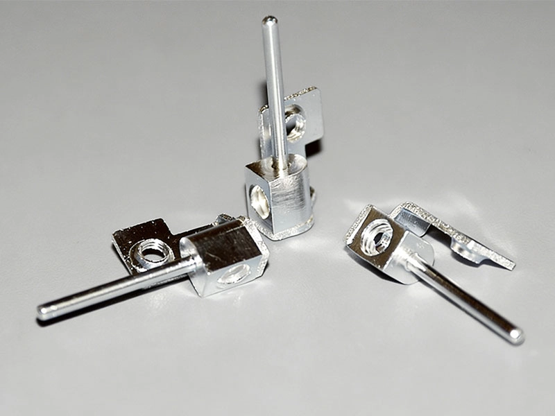
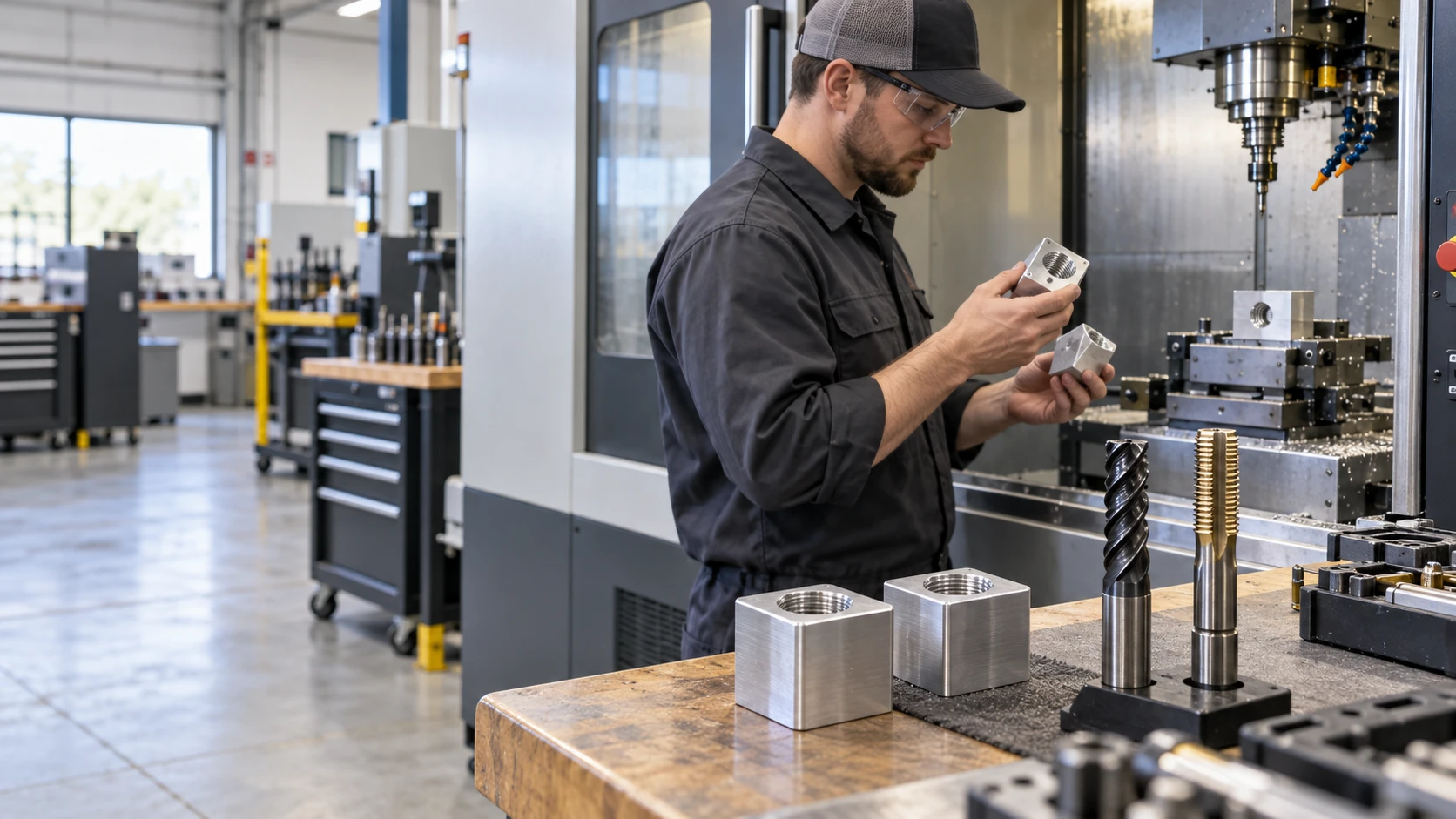
Not every hole, thread, bore, or datum must be forced into the stamping die. Tapping, reaming, machining, or a light calibration operation may be safer for a critical interface. Classify features as stamped, stamped with a tolerance change, or completed in a secondary process. This prevents an expensive die revision when a short downstream operation would protect function.
Strip Layout and Die Architecture
Strip layout affects material use, carrier strength, orientation, burr direction, and station count. Progressive dies suit repeat features across a coil; compound dies combine blanking and piercing; drawing dies form depth but require control of flow, wrinkles, thinning, and draw beads. Review the concept against geometry, press capability, feed direction, and a suitable simulation or trial plan.
Materials, Tolerances, and Secondary Operations
Material selection influences tool wear, burrs, springback, cracking, conductivity, corrosion, and cost. Confirm the approved grade and alternatives before tool steel and clearances are finalized; a substitution may form differently or change tonnage.
Separate general tolerances from functional tolerances. Tightening every dimension can increase stations, tool complexity, inspection effort, and rework without improving assembly. Define critical hole positions, flatness, bend angles, contact faces, and profile features, then specify how they will be measured after forming and any secondary work.
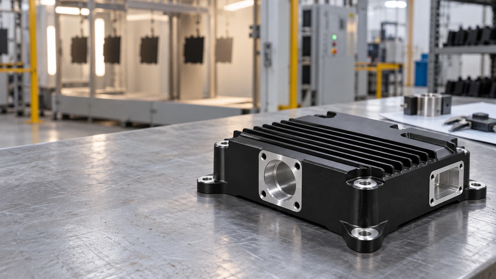
Finishing also belongs in DFM. Deburring, tumbling, plating, powder coating, painting, cleaning, and assembly can change dimensions or mask defects. Identify coated or plated surfaces, no-finish zones, thread protection, and cosmetic standards before the first trial. Buyers seeking Dienstleistungen im Bereich kundenspezifischer Metallstanzung und Werkzeugbau should ask how the die design accounts for these downstream operations.
Change-Control Gates That Protect the Tool Investment
Use formal gates instead of informal email approvals. A workable sequence is:
- Design input freeze: function, material, thickness, interfaces, quantity, and finish are documented.
- DFM sign-off: geometry, strip layout, die concept, tolerances, and secondary operations are reviewed.
- Tool release: the controlled drawing and revision are approved for detailed design and procurement.
- Tryout review: samples are checked for dimensions, burrs, cracks, wrinkles, springback, and assembly fit.
- First-article approval: corrections are closed, records are issued, and later changes follow a defined process.
If a change arrives after tool release, classify it before authorizing work. A note may need no steel change; a moved hole may need an insert; a new bend or thickness may require station redesign. Record affected components, samples, schedule impact, and approval owner so an urgent request becomes a controlled decision.
What to Include in a Tooling DFM RFQ
Send the latest 2D drawing, 3D model, revision history, material and thickness, flat pattern, annual and lifetime quantities, press constraints, critical tolerances, burr direction, finish, secondary operations, inspection requirements, and open design issues. State whether the part is a prototype, released design, or CNC conversion.
Ask each supplier for a marked-up drawing or DFM report showing proposed radii, hole changes, forming sequence, strip concept, datums, and unresolved risks. Clarify tool ownership, maintenance, sharpening, spares, modification charges, trial samples, and engineering-change pricing so metal stamping services quotes cover comparable scope.
Working With an Integrated Stamping and Tooling Supplier
CK Metal Tech describes precision tooling design and manufacture alongside high-speed stamping, CNC machining, sheet metal fabrication, finishing, inspection, and assembly. Its published tooling scope includes progressive, drawing, and compound die approaches, with stamping materials such as brass, copper alloys, steel, stainless steel, and cold-rolled strip.
The supplier also presents a progressive die stamping terminal strip as a repeatable formed-component example. Capabilities alone do not prove a specific die’s tolerance or life; CK Metal Tech should confirm the drawing, material, quantity, press window, inspection plan, and change-control rules.
For broader supplier-selection context, see the custom metal stamping and tooling supplier guide, then use the DFM report and approved revision as the working baseline for the new project.
Abschluss
Tooling DFM prevents die rework by exposing forming limits, material behavior, tolerance conflicts, strip-layout tradeoffs, and finishing risks before release. The process separates controlled interfaces from flexible features, documents secondary operations, and uses approval gates through first article.
Prepare the drawing revision, material, thickness, quantity, critical interfaces, finish, inspection needs, and known changes before requesting a review. OEM teams can contact CK Metal Tech for a stamping DFM review and ask for a route recommendation, marked-up risks, trial plan, and change-control scope.
Häufig gestellte Fragen
When should tooling DFM start on a metal stamping project?
Start after the functional concept is clear but before detailed die design or steel procurement. The review should precede production-tool release and include material, interfaces, quantities, tolerances, and finishing.
Which design changes are most likely to require die rework?
Moved holes, changed bend directions, new flanges, altered material thickness, revised draw depth, and changes to critical datums can affect stations or die components. The actual impact depends on the tool architecture.
Can a stamped part use secondary machining?
Yes. Tapping, reaming, milling, or calibration may be appropriate for precision bores, threads, datum faces, or other features that are risky to hold directly in forming. Classify these operations during DFM.
What should a supplier include in a tooling DFM report?
Request a marked-up drawing, forming and strip-layout assumptions, proposed die route, material risks, tolerance comments, secondary operations, trial plan, inspection points, and a list of open decisions requiring customer approval.

Hinterlasse eine Antwort