



CHUANGKAI

A Saya l A N D

Memuat


Lembaran Logam & Pengecatan

HUBUNGI KAMI
Vektor

Pertanyaan yang Sering Diajukan (FAQ)

Hubungi kami foto

Komponen stamping presisi diproduksi menggunakan cetakan presisi tinggi melalui penjepitan dan penempatan satu stasiun dalam proses penempaan. Mengingat persyaratan akurasi dimensi dan toleransi posisi yang ketat untuk benda kerja pada mesin stamping, proses penyelesaian yang ketat termasuk penajaman cetakan, perlakuan panas, perlakuan permukaan, dan perakitan sangat penting. Karena komponen ini biasanya diproduksi dalam jumlah kecil atau sebagai bagian terpisah, volume produksinya relatif rendah, yang akibatnya memberikan persyaratan yang kurang ketat pada mesin. Selama proses stamping, material mengalir ke dalam rongga cetakan melalui celah-celah pada cetakan. Di bawah tekanan, material mengalami pemisahan atau deformasi plastis untuk mencapai bentuk dan struktur yang diinginkan. Setelah pelepasan tekanan, proses pembentukan yang terkontrol menghasilkan produk jadi. Hal ini menjadikan stamping sebagai teknik penarikan dingin klasik. Dalam produksi aktual, untuk memastikan kualitas produk, meningkatkan efisiensi, mengurangi limbah, dan menghemat energi, produsen biasanya menerapkan langkah-langkah strategis: 1. Menggunakan alat dengan tepat. 2. Memilih bahan baku yang tepat. 3. Merumuskan peraturan proses yang wajar. 4. Meningkatkan pelatihan teknis operator. 5. Meningkatkan otomatisasi mesin. 6. Meningkatkan kondisi kerja. Karakteristik pembuatan komponen stamping: (1) Tingkat pemanfaatan material yang tinggi. (2) Produk kompleks dapat dibuat dari lembaran yang relatif tipis. (3) Dapat dibuat menjadi berbagai struktur yang mengandung kolom struktural. (4) Dapat membentuk rongga dinding tebal. (5) Dapat dibuat menjadi material papan dengan area yang luas. (6) Mudah dimekanisasi. (7) Mempermudah penyelesaian mekanisasi dan otomatisasi. (8) Mudah untuk menyelesaikan sistem.

Pembuatan komponen mekanik presisi biasanya melibatkan pemrosesan komponen untuk mesin presisi, yang membutuhkan pencapaian akurasi yang sangat tinggi. Oleh karena itu, selain memahami persyaratan material spesifik dan teknik umum untuk pemesinan komponen mekanik presisi, penting untuk mengetahui proses produksi secara lengkap. Di bawah ini, kami akan menguraikan lima tahapan pembuatan komponen mekanik presisi. 1. Pemesinan kasar Pertimbangan utama adalah untuk meningkatkan produktivitas. Sebagian besar kapasitas pemesinan pada setiap permukaan dihilangkan, dan pemesinan menghasilkan bidang referensi. 2. Semi-finishing Biasanya menghilangkan cacat yang mungkin dihasilkan setelah pemesinan kasar, dan melakukan pemesinan permukaan primer dan sekunder secara bersamaan. Penting untuk mencapai akurasi pemesinan tetap untuk mempermudah persiapan tahap finishing dan memastikan kapasitas finishing yang moderat. 3. Finishing Pada tahap finishing, jumlah pemotongan yang besar, jumlah umpan yang kecil, dan kedalaman pemotongan biasanya digunakan untuk menghilangkan kapasitas pemesinan yang tersisa dari semi-finishing, sehingga permukaan komponen mekanik presisi dapat mencapai standar teknis gambar. 4. Pemolesan Terutama digunakan untuk mengurangi kekasaran permukaan atau memperkuat permukaan yang diproses, dan terutama digunakan untuk pemrosesan permukaan dengan persyaratan kekasaran permukaan yang tinggi. 5. Pemesinan ultra-presisi Umumnya, akurasi pemesinan benda kerja adalah 0,1-0,01μm dan nilai kekasaran permukaan ra kurang dari atau sama dengan 0,001μm melalui pengeboran presisi, pemotongan cermin presisi, penggerindaan presisi, dan pemolesan. Proses pemesinan presisi lima tahap untuk komponen mekanik berkembang dari kasar ke halus, dengan peningkatan akurasi secara bertahap. Melalui pendekatan sistematis ini, komponen mencapai spesifikasi yang dibutuhkan sesuai kebutuhan pelanggan. Yuntuo Machining mengkhususkan diri dalam pembuatan komponen mekanik presisi. Kami menyediakan layanan yang disesuaikan berdasarkan gambar dan material yang diberikan klien, menghasilkan komponen yang direkayasa secara presisi yang memenuhi semua harapan klien.

kirimkan kami secara gratis
pesan


    terkini
    artikel blog

    How Security Inspection Equipment Chassis Are Made: Sheet Metal Fabrication, Powder Coating and Assembly

    08
    Oktober
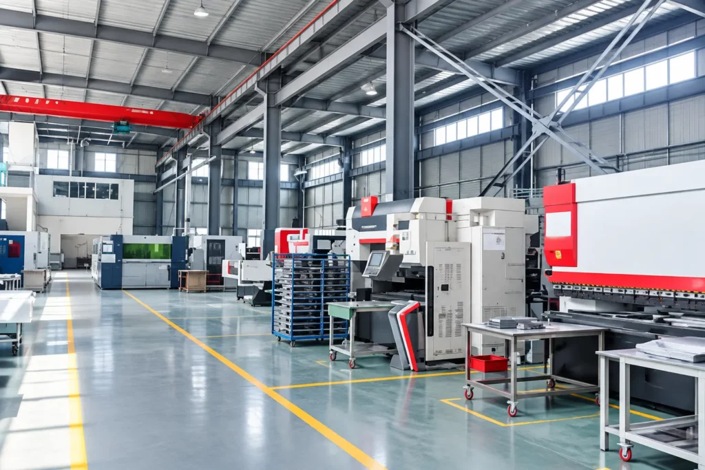
    How Security Inspection Equipment Chassis Are Made Sheet Metal Fabrication, Powder Coating and Assembly

    A security inspection equipment chassis has to do more than enclose electronics. It must preserve alignment, protect modules, allow service access, and present a controlled exterior in demanding public environments. The practical route is integrated: design the sheet metal structure around the equipment, apply a suitable finish, then complete and verify the assembly as one system. This guide covers the key decisions buyers should clarify before quoting. For a product-level reference, review CK Metal Tech’s perakitan sasis peralatan inspeksi keamanan.

    A well-designed sheet metal equipment enclosure coordinates rails, doors, cable routes, ventilation, grounding, and mounting points before material is cut. Treating fabrication, coating, and assembly as separate purchases can create fit-up gaps or late rework. Good engineering-to-production handoff is central to predictable equipment chassis assembly.

    Why Security Inspection Chassis Design Requires More Than a Metal Shell

    Security inspection equipment often operates where public access, continuous duty, and technician access overlap. The chassis must support the equipment without obstructing its working envelope, while remaining practical to clean, service, move, and integrate with adjacent structures. A panel that looks acceptable in a drawing can still block a cable bend, restrict a door swing, or make a high-use component difficult to replace.

    Before fabrication, confirm the structural loads, access panels, heat and cable-routing needs, and surfaces requiring corrosion or abrasion resistance. Those answers help determine whether to use SPCC cold-rolled steel, SUS304 stainless steel, aluminum profiles, or a combination. Material selection should follow the equipment and environment.

    From Flat Sheet to Serviceable Chassis: The Manufacturing Flow

    A controlled workflow normally starts with drawing and interface review, followed by CNC laser cutting, CNC bending, welding or riveting, surface preparation, electrostatic powder coating, component installation, and system debugging. Each step must protect the dimensions and interfaces established previously so the finished enclosure remains serviceable after coating and assembly.
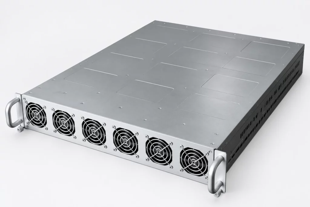
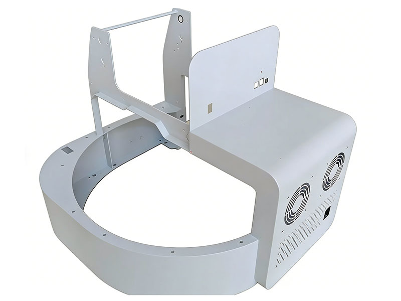
    Sheet metal security inspection equipment chassis ready for assembly

    Sheet Metal Fabrication Sets the Geometry

    The fabrication stage converts the equipment envelope into panels, brackets, doors, bases, rails, and other structural parts. A precision sheet metal fabrication review should confirm bend allowances, hole locations, tolerance stack-up, weld access, hardware clearances, and the sequence used to maintain squareness. CNC laser cutting supports repeatable openings and mounting patterns, while CNC bending establishes stiffness and alignment. Welding or riveting is selected according to load, access, finish, and service requirements. CK Metal Tech’s precision sheet metal fabrication capability can be evaluated against the project’s drawings and interface needs.

    Small details can determine whether the final security inspection chassis is easy to use: front maintenance doors, removable covers, guide rails, grounding points, cable entries, and lock clearances. The drawing review should also identify surfaces that must remain uncoated, threaded holes needing protection, and areas where welded distortion could affect fit.

    Powder Coating Creates the Protective Outer Layer

    Powder coating is more than a color choice. Pretreatment, masking, grounding, edge coverage, curing, and film build all influence how the finished chassis performs and assembles. A powder coated chassis can provide a clean, durable exterior for many indoor equipment applications, but it is not automatically suitable for every chemical, humidity, outdoor, or cleaning environment. The coating system should be matched to the substrate and exposure, and any appearance or corrosion target should be confirmed in the project specification. CK Metal Tech’s powder coating service can be considered as part of that finish review.

    Before coating, identify threaded interfaces, contact points, sliding surfaces, labels, and grounding locations that require masking or post-process inspection. After coating, doors and rails should be checked for build-up that could affect movement. Color consistency matters in public-facing equipment, but functional checks matter just as much: an attractive finish cannot compensate for blocked threads, poor bonding, or a panel that no longer seats correctly.

    Equipment Chassis Assembly Closes the Loop

    Assembly is where the fabricated structure is tested against real service conditions. Depending on the agreed scope, it may include stainless-steel rails, locks, panels, brackets, fasteners, and equipment modules, followed by fit checks and system debugging. The assembly team should verify door swing, rail travel, fastener access, cable paths, grounding continuity, and the relationship between removable parts and maintenance tasks. This is also the stage to catch coating damage, interference, missing hardware, or tolerance issues before packaging.

    A supplier that handles fabrication, finishing, and assembly together can reduce handoff risk, but the scope still needs to be written clearly. Specify whether the deliverable is a bare enclosure, a powder-coated structure, a partially equipped chassis, or a tested assembly. Clear scope prevents a technically correct part from becoming an incomplete project deliverable.

    What to Confirm Before Requesting a Quotation

    A useful RFQ gives the manufacturer enough information to evaluate structure, finish, and assembly together. The following items turn a general request for a custom equipment chassis into a reviewable manufacturing package:

    1. Envelope and interfaces: provide overall dimensions, equipment clearances, door swing, mounting-hole patterns, cable-entry locations, and connections to conveyors, cabinets, or adjacent frames.
    2. Material and finish: state preferred materials, visible-surface expectations, coating color, gloss or texture requirements, uncoated areas, and exposure to moisture, cleaning agents, or abrasion.
    3. Load and operating conditions: identify static or moving loads, vibration, heat sources, humidity, indoor or outdoor use, service frequency, and any target sealing level that must be verified against the final design.
    4. Assembly scope: list rails, locks, panels, fasteners, modules, wiring interfaces, and debugging or fit-check activities that should be included, along with customer-supplied components.
    5. Quality and delivery information: include drawing revision, quantity, inspection expectations, packaging constraints, and acceptance points that determine whether the completed chassis is ready for installation.

    Where This Approach Fits

    The same fabrication-to-assembly logic supports several security environments, but priorities differ. Airports, stations, and subway facilities may emphasize clean public-facing surfaces, reliable access doors, and easy maintenance. Customs areas and logistics parks may emphasize impact resistance, equipment protection, cable management, and repeatable material-handling integration. Temporary screening may require compact transport and a finish that remains presentable after repeated handling.

    Reflect these differences in the drawing package and acceptance criteria. A chassis designed for a controlled indoor room should not automatically be treated as an outdoor enclosure. A coating selected for appearance should not be assumed to provide a particular sealing or corrosion performance without confirming joints, doors, gaskets, fasteners, and penetrations.

    Kesimpulan

    A dependable security inspection equipment chassis is the result of coordinated decisions, not a single fabrication operation. Sheet metal design establishes the structure and interfaces. Powder coating protects and presents the exterior when the coating system matches the environment. Equipment chassis assembly confirms that doors, rails, fasteners, modules, and service access work together. By defining materials, loads, clearances, finish requirements, assembly scope, and acceptance checks before production, buyers can reduce avoidable rework and compare suppliers on practical project fit rather than enclosure appearance alone.

    Pertanyaan yang Sering Diajukan (FAQ)

    What materials are commonly used for a security inspection chassis?

    Common options include SPCC cold-rolled steel, SUS304 stainless steel, and aluminum profiles. The choice depends on structure, corrosion exposure, weight, weldability, finish, and equipment interfaces.

    Does powder coating replace sealing or environmental protection?

    No. Powder coating protects coated surfaces, but overall environmental performance also depends on joints, doors, gaskets, fasteners, cable penetrations, and the enclosure design. Any target sealing level should be confirmed against the final specification.

    What does equipment chassis assembly usually include?

    It may include rails, locks, panels, brackets, fasteners, equipment modules, fit checks, and system debugging. Define the scope in the RFQ so the quotation matches the intended deliverable.

    Can the chassis be designed for front maintenance?

    Yes, front maintenance doors, removable panels, guide rails, and accessible fasteners can be incorporated when the equipment layout and service clearances are known. The design should be checked against real replacement and inspection tasks.

    Request a Project-Specific Chassis Review

    To evaluate a custom equipment chassis, share the equipment envelope, module layout, material preference, coating environment, expected load, drawing revision, quantity, and application conditions with CK Metal Tech. The technical team can then confirm feasible fabrication, finish, assembly scope, and specification gaps. Use the request application support route when you are ready to discuss the project.

    CNC Machining Tolerances: When Tight Tolerances Are Necessary – and When They Increase Cost

    01
    Oktober


    CNC Machining Tolerances When Tight Tolerances Are Necessary - and When They Increase Cost

    When a drawing applies a very tight tolerance to every feature, the part can become more expensive without becoming more functional. CNC machining tolerances should be driven by fit, movement, sealing, alignment, and inspection needs – not by making every number look precise. A practical strategy gives critical features the right control and leaves non-critical dimensions at a manufacturable default. This guide explains when tight tolerances earn their cost and how to communicate them to a CNC supplier.

    Ask what the feature does in the assembly. If it locates a bearing, controls a seal, or determines whether interchangeable parts fit, tighter control may be justified. If it is an external surface with clearance, a tighter number may only increase setup time, inspection, scrap risk, and quotation value.

    What CNC Machining Tolerances Actually Control

    A tolerance is the permitted variation around a nominal dimension. It is different from machine resolution or a general accuracy claim. The result depends on tooling, workholding, material, geometry, temperature, process sequence, and measurement method. Drawings may also control position, flatness, runout, surface finish, or thread fit; adding decimals cannot correct a poor datum scheme.

    As a planning reference, some suppliers use +/-0.005 in (0.13 mm), while +/-0.001 in (0.025 mm) or tighter may require additional controls. These values are illustrative, not universal promises. Confirm capability against material, geometry, quantity, equipment, and inspection.

    When Tight Tolerances Are Necessary

    Tight tolerances are justified when variation can change function, assembly, safety, or service life. The need is usually feature-specific, not every feature.

    Mating and Moving Features

    Bearing seats, shafts, sliding guides, locating pins, press fits, and clearance fits depend on relationships between features. A shaft may need close control while a nearby shoulder does not. Specify the fit, material pair, temperature range, and motion instead of tightening the entire part.

    Sealing and Pressure-Related Surfaces

    O-ring grooves, sealing lands, mating flanges, valve seats, and fluid passages may need tighter size, form, surface-finish, or flatness control. Identify the sealing method, contact surface, finish, and leakage or pressure requirement rather than relying on a nominal diameter alone.

    Alignment, Datums, and Interchangeability

    Tight control can be valuable when a part locates a sensor, aligns a mechanical path, interfaces with a replaceable module, or accumulates with other parts. Position, perpendicularity, parallelism, and datum relationships may matter more than one linear dimension.

    Inspection-Critical or Safety-Relevant Features

    Dimensions tied to calibration, safety clearance, regulatory function, or a customer’s acceptance test deserve a defined measurement method and record. State whether inspection uses a CMM, gauges, vision, or functional testing so the tolerance is realistic and repeatable.

    When Tight Tolerances Increase Cost Without Adding Value

    A tight tolerance becomes expensive when it pushes a feature beyond the normal capability of the selected process. The added cost comes from the controls needed to hold and prove it.

    More Setups and Slower Cutting

    Very small limits may require extra passes, smaller tools, lower cutting loads, special workholding, or a second operation. Re-fixturing introduces another opportunity for datum shift, and the cost can exceed the value of the feature.

    Material, Geometry, and Temperature Effects

    Thin walls, deep pockets, long shafts, interrupted cuts, and uneven stock can deflect or distort. Aluminum, stainless steel, plastics, and heat-treated materials also respond differently to heat and clamping. A tolerance that is reasonable on a rigid block may be costly on a slender component.

    Inspection, Rework, and Scrap

    Tighter limits often require more in-process checks, calibration, final inspection, and documentation. Small variation can create rework or scrap even when the part would perform correctly. Cost also rises when the supplier inspects features the assembly never uses.

    How to Match the Tolerance to the Feature

    A better approach is to assign tolerances by function and then confirm that the manufacturing route can support them. Use the following decision rule during design review:

    1. If the feature mates or moves, define the fit or clearance and control the mating surfaces.
    2. If it locates another component, control position and datum relationships rather than every surrounding dimension.
    3. If it seals, define sealing geometry, finish, flatness, and inspection method.
    4. If it is cosmetic or non-functional, use a reasonable general tolerance and specify appearance separately.
    5. If no one can explain how it will be used or inspected, do not make the tolerance unnecessarily tight.

    Holes and shafts are common sources of over-specification. A clearance hole does not need the same control as a locating hole. A threaded hole needs the correct thread standard, depth, and verification; an extremely tight minor diameter may not improve the connection. Call out flatness and parallelism when they control contact or alignment.

    Keep surface finish and edge requirements separate from dimensional tolerance. A smoother finish may support sealing or sliding, while an edge break supports assembly and handling.

    What to Put on the Drawing and RFQ

    A supplier can price CNC machining more accurately when the drawing separates critical requirements from general ones. Include material, quantity, part size, critical features, datums, general tolerance standard, surface finish, threads, heat treatment, coating, and inspection records. State whether the requirement applies to a prototype, lot, or every interchangeable part.

    For a practical document package, use a structured CNC machining RFQ checklist and mark the dimensions that affect fit, sealing, motion, or final acceptance. A supplier should be able to see which features require a capability review before quoting and which dimensions can follow the agreed general tolerance.

    Define the measurement reference too: datum scheme, temperature when relevant, gauge or CMM method, sampling plan, and first-article reporting. This prevents the manufacturer and customer from evaluating the same feature in different ways.

    How a CNC Supplier Should Verify Tight Features

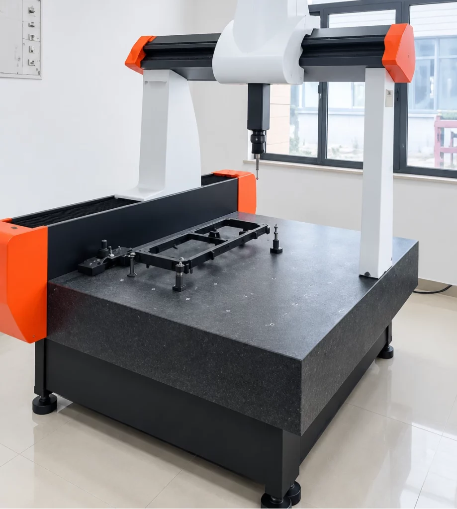
    Tolerance control is a process responsibility, not only a final inspection activity. A capable supplier reviews high-risk features, chooses a stable setup, monitors tool wear, and inspects critical dimensions. Micrometers and bore gauges may suit simple sizes, while a CMM or 2.5D system may suit positional relationships and profiles.

    Coordinate measuring machine used for CNC part inspection

    CK Metal Tech lists multi-axis CNC equipment, a 5-axis Swiss-type lathe, CNC lathes and milling machines, plus grinding, thread rolling, tapping, drilling, cleaning, polishing, and surface-preparation resources. Its laboratory resources include a 1200 x 1000 x 800 mm coordinate measuring machine, a 2.5D measurement system, and metallographic microscope and Vickers hardness equipment. Match those resources to the actual feature and inspection plan.

    You can review the company’s precision machining capabilities and ask which process route and measurement method fit the drawing. Its quality management information can also help procurement teams understand the broader production and verification context.

    Kesimpulan

    The best CNC machining tolerance strategy is selective. Tight tolerances are worth paying for when they protect a fit, seal, alignment relationship, safety function, or required inspection result. They add avoidable cost when applied to clearance features, cosmetic surfaces, or dimensions that do not affect assembly. By separating general tolerances from critical callouts, defining datums and inspection methods, and discussing process capability before release, engineering and procurement teams can improve part quality while keeping the quotation tied to real performance.

    Pertanyaan yang Sering Diajukan (FAQ)

    What is a typical CNC machining tolerance?

    There is no universal value. Many shops use around +/-0.005 in (0.13 mm) for general features, while tighter values require review of material, geometry, equipment, quantity, and inspection. Use the supplier’s confirmed capability.

    Are tighter tolerances always better?

    No. A tighter tolerance is better only when it protects a functional requirement. Otherwise it can increase setups, inspection, rework, and scrap without improving the part in service.

    Which CNC features usually need tight tolerances?

    Bearing seats, shafts, locating holes, sealing surfaces, precision threads, alignment datums, and interchangeable interfaces commonly need closer control. The value depends on the mating parts and operating conditions.

    How can a buyer reduce CNC machining cost without lowering quality?

    Identify critical features, relax non-functional dimensions, use clear datums, avoid unnecessary re-fixturing, and agree on inspection before production. A targeted scheme often delivers better value than a uniformly tight drawing.

    Request a Tolerance and DFM Review

    Share the part drawing, material, quantity, critical fit or sealing requirements, surface finish, tolerance callouts, and inspection expectations with CK Metal Tech. The engineering team can review whether the requested CNC machining tolerances match the feature function and recommend a process and measurement route. Use the request a tolerance review route for a project discussion.

    Tooling DFM for Metal Stamping: Prevent Die Rework

    25
    September


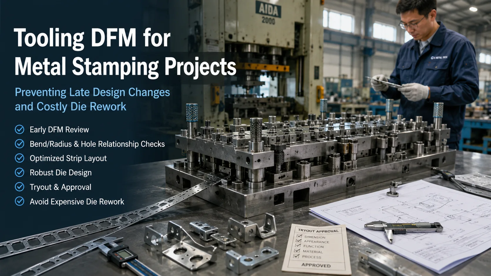
    Tooling DFM for Metal Stamping Projects Preventing Late Design Changes and Costly Die Rework

    Tooling DFM (design for manufacturing) connects a stamped-part drawing to a workable die, press route, material, and inspection plan before steel is cut. Its value is highest before tool release, when a change to a bend, hole, radius, or strip layout is still a drawing edit rather than die rework. The goal is to freeze the right requirements early and expose risks while they remain inexpensive to correct.

    A disciplined review asks: Can the geometry be formed from the selected stock? Can the die support tolerance and tool-life needs? Can the finished part be inspected and assembled? What happens if the design changes after tooling starts? These answers create a gate between prototype approval and production tooling.

    What Tooling DFM Should Confirm Before Die Design

    Start with function, stock form, and production intent

    Begin with the part’s job, not just its current CAD shape. Identify load paths, contact surfaces, spring features, sealing edges, electrical interfaces, and cosmetic faces. Then confirm material grade, temper, thickness, coil or blank form, grain direction where relevant, and expected annual and lifetime quantities. A part designed around CNC machining may contain solid sections, sharp internal corners, or tolerances that are unsuitable for sheet-metal forming.

    The DFM review should also state whether the route is progressive die stamping, compound die stamping, drawing, bending, or a hybrid with secondary machining. Buyers evaluating precision stamping tooling design and manufacturing should expect the supplier to explain why the proposed route fits the geometry and demand rather than simply quote a die price.

    Freeze interfaces before optimizing minor features

    Late changes are most disruptive when they affect mounting holes, connector locations, datums, bend directions, mating edges, or the finished envelope. Mark these as controlled interfaces; review cosmetic improvements and non-critical reliefs separately. This prevents a low-risk change from reopening the entire die.

    Geometry Checks That Prevent Die Rework

    Review bend radii, hole relationships, and edge distances

    Inside bend radius, material thickness, hole-to-edge distance, slot orientation, and flange length determine whether a feature can be formed without cracking, distortion, or an unstable die condition. Small holes close to a bend may deform during forming. Narrow webs can tear or buckle. Sharp corners often require a radius, relief, or a different operation sequence.

    The drawing should identify the formed condition, not only the flat pattern. Show bend direction, critical radii, profile tolerances, and any areas where burr direction matters. If a feature is possible only after a design adjustment, document the adjustment and obtain approval before tool detailing.

    Account for springback and forming variation

    Springback depends on material, thickness, grain direction, bend geometry, tooling, and process controls. A nominal CAD angle is not proof of the released angle. The supplier should identify compensation, restrike, coining, or measurement steps where the assembly requires a stable formed position. Do not hide a springback problem with a broad tolerance that later causes poor fit.

    Decide which features stay secondary

    Not every hole, thread, bore, or datum must be forced into the stamping die. Tapping, reaming, machining, or a light calibration operation may be safer for a critical interface. Classify features as stamped, stamped with a tolerance change, or completed in a secondary process. This prevents an expensive die revision when a short downstream operation would protect function.


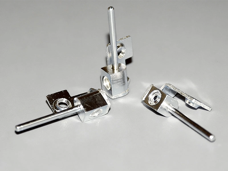
    Precision-stamped PCB terminal block with bending, tapping and drilling

    Strip Layout and Die Architecture

    Strip layout affects material use, carrier strength, orientation, burr direction, and station count. Progressive dies suit repeat features across a coil; compound dies combine blanking and piercing; drawing dies form depth but require control of flow, wrinkles, thinning, and draw beads. Review the concept against geometry, press capability, feed direction, and a suitable simulation or trial plan.

    Materials, Tolerances, and Secondary Operations

    Material selection influences tool wear, burrs, springback, cracking, conductivity, corrosion, and cost. Confirm the approved grade and alternatives before tool steel and clearances are finalized; a substitution may form differently or change tonnage.

    Separate general tolerances from functional tolerances. Tightening every dimension can increase stations, tool complexity, inspection effort, and rework without improving assembly. Define critical hole positions, flatness, bend angles, contact faces, and profile features, then specify how they will be measured after forming and any secondary work.

    Finishing also belongs in DFM. Deburring, tumbling, plating, powder coating, painting, cleaning, and assembly can change dimensions or mask defects. Identify coated or plated surfaces, no-finish zones, thread protection, and cosmetic standards before the first trial. Buyers seeking layanan pencetakan dan pembuatan perkakas logam sesuai pesanan should ask how the die design accounts for these downstream operations.

    Change-Control Gates That Protect the Tool Investment

    Use formal gates instead of informal email approvals. A workable sequence is:

    • Design input freeze: function, material, thickness, interfaces, quantity, and finish are documented.
    • DFM sign-off: geometry, strip layout, die concept, tolerances, and secondary operations are reviewed.
    • Tool release: the controlled drawing and revision are approved for detailed design and procurement.
    • Tryout review: samples are checked for dimensions, burrs, cracks, wrinkles, springback, and assembly fit.
    • First-article approval: corrections are closed, records are issued, and later changes follow a defined process.

    If a change arrives after tool release, classify it before authorizing work. A note may need no steel change; a moved hole may need an insert; a new bend or thickness may require station redesign. Record affected components, samples, schedule impact, and approval owner so an urgent request becomes a controlled decision.

    What to Include in a Tooling DFM RFQ

    Send the latest 2D drawing, 3D model, revision history, material and thickness, flat pattern, annual and lifetime quantities, press constraints, critical tolerances, burr direction, finish, secondary operations, inspection requirements, and open design issues. State whether the part is a prototype, released design, or CNC conversion.

    Ask each supplier for a marked-up drawing or DFM report showing proposed radii, hole changes, forming sequence, strip concept, datums, and unresolved risks. Clarify tool ownership, maintenance, sharpening, spares, modification charges, trial samples, and engineering-change pricing so metal stamping services quotes cover comparable scope.

    Working With an Integrated Stamping and Tooling Supplier

    CK Metal Tech describes precision tooling design and manufacture alongside high-speed stamping, CNC machining, sheet metal fabrication, finishing, inspection, and assembly. Its published tooling scope includes progressive, drawing, and compound die approaches, with stamping materials such as brass, copper alloys, steel, stainless steel, and cold-rolled strip.

    The supplier also presents a progressive die stamping terminal strip as a repeatable formed-component example. Capabilities alone do not prove a specific die’s tolerance or life; CK Metal Tech should confirm the drawing, material, quantity, press window, inspection plan, and change-control rules.

    For broader supplier-selection context, see the custom metal stamping and tooling supplier guide, then use the DFM report and approved revision as the working baseline for the new project.

    Kesimpulan

    Tooling DFM prevents die rework by exposing forming limits, material behavior, tolerance conflicts, strip-layout tradeoffs, and finishing risks before release. The process separates controlled interfaces from flexible features, documents secondary operations, and uses approval gates through first article.

    Prepare the drawing revision, material, thickness, quantity, critical interfaces, finish, inspection needs, and known changes before requesting a review. OEM teams can contact CK Metal Tech for a stamping DFM review and ask for a route recommendation, marked-up risks, trial plan, and change-control scope.

    Pertanyaan yang Sering Diajukan (FAQ)

    When should tooling DFM start on a metal stamping project?

    Start after the functional concept is clear but before detailed die design or steel procurement. The review should precede production-tool release and include material, interfaces, quantities, tolerances, and finishing.

    Which design changes are most likely to require die rework?

    Moved holes, changed bend directions, new flanges, altered material thickness, revised draw depth, and changes to critical datums can affect stations or die components. The actual impact depends on the tool architecture.

    Can a stamped part use secondary machining?

    Yes. Tapping, reaming, milling, or calibration may be appropriate for precision bores, threads, datum faces, or other features that are risky to hold directly in forming. Classify these operations during DFM.

    What should a supplier include in a tooling DFM report?

    Request a marked-up drawing, forming and strip-layout assumptions, proposed die route, material risks, tolerance comments, secondary operations, trial plan, inspection points, and a list of open decisions requiring customer approval.

    CNC Surface Finish: When to Turn, Mill, Grind or Polish

    24
    September


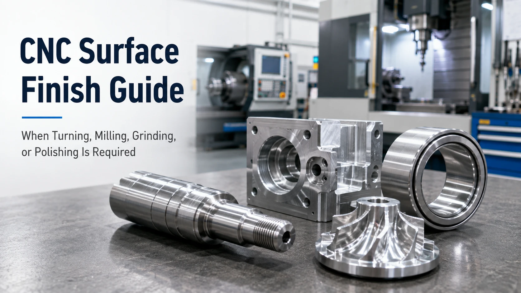
    CNC Surface Finish Guide When Turning, Milling, Grinding, or Polishing Is Required

    Choosing a CNC surface finish should start with what the part must do, not with a favorite machine or a shiny appearance. CNC turning or milling may meet the drawing on many parts. Grinding becomes useful when a surface must hold tighter geometry after heat treatment or support a bearing, seal, or sliding fit. Polishing is justified when friction, cleanability, reflectivity, or cosmetic uniformity matters after the geometry is already under control.

    For OEM buyers, the practical decision is to connect the required surface condition to the manufacturing sequence. A clear drawing identifies functional faces, roughness parameters, edge treatment, and inspection method so a supplier can select turning machining, CNC milling machining, grinding machining, or polishing without adding unnecessary operations.

    Read the Drawing Before Choosing a Finish

    Surface roughness is a functional requirement

    Ra and Rz describe aspects of a measured profile, while lay describes tool-mark direction. Roughness alone does not define flatness, roundness, waviness, burrs, or visual uniformity. A shaft can meet an Ra target yet fail a seal because of a damaged edge or poor cylindricity.

    The drawing should identify the datum system, critical dimensions, roughness symbols, surface lay where relevant, edge breaks, and areas that may not be touched by a later process. If the specification uses machining finish symbols, pair them with a measurable requirement and a defined inspection location. Avoid writing only “smooth finish” or “polished” because different suppliers may interpret those words differently.

    Separate critical and non-critical surfaces

    Mark bearing seats, seal grooves, sliding faces, threads, electrical contacts, cosmetic panels, and hidden surfaces. Leave non-critical faces at the normal CNC condition and reserve extra work for functional areas to control cost and dimensions.

    When CNC Turning Is Enough

    CNC turning is usually the first process for shafts, pins, sleeves, bushings, collars, and other rotational parts. It can provide a consistent texture when diameter, concentricity, shoulders, threads, and edges meet the drawing. Adding grinding or polishing only for appearance can remove stock and increase handling.


    CNC turned 304316L stainless steel hydraulic fitting with threaded machined surface

    Turning is often sufficient when the surface is not a hardened bearing fit, demanding seal, or fine cosmetic face. Tool nose radius, insert condition, feed, speed, workholding, and material influence the profile. The supplier should confirm achievable roughness and the deburring pass.

    Inspect turned surfaces where they control assembly: diameter, roundness or concentricity, thread engagement, shoulder squareness, burrs, and lay. A profilometer reading cannot replace dimensional checks.

    When CNC Milling Is Enough

    CNC milling is the normal starting point for plates, brackets, pockets, housings, slots, and contoured faces. A suitable cutter, stable workholding, and a finishing pass can produce a reliable surface without secondary work. Results depend on cutter, step-over, toolpath, material, and whether the face is visible or functional.

    Milling may be enough for mounting faces, pockets, and general components when normal tool marks are acceptable. For visible faces, specify acceptable marks and transitions. For mating faces, define flatness, parallelism, and hole position in addition to roughness.

    Buyers comparing custom CNC machining services should ask for a sample or first-article review that shows the actual toolpath and fixture condition. A finish achieved on a small coupon may not represent a large plate, a deep pocket, or a thin wall that can vibrate during cutting.

    When Grinding Is Required

    Grinding is controlled abrasive stock removal for surfaces that need tighter size, geometry, or roughness than turning or milling can hold. It is commonly considered for hardened shafts, bearing journals, precision bores, guide surfaces, sealing diameters, and flat faces. Internal, external cylindrical, centerless, and surface grinding suit different geometries.

    Plan grinding in the drawing and process route. Leave stock, define the post-heat-treatment datum, and protect edges from burns or breakage. A route may be rough turning or milling, heat treatment, finish grinding, cleaning, and inspection. Hardness, length, wall thickness, and clamping affect the result.

    A grinding callout does not solve distortion automatically. Measure runout, cylindricity, taper, flatness, and size at functional locations, and review protection and datum relationships for threads, keyways, and cross-holes.

    When Polishing Is Required

    Polishing is appropriate when an application needs lower friction, easier cleaning, controlled reflectivity, or a uniform visible appearance after machining. It is often used on stainless steel, exposed hardware, fluid-contact areas, and surfaces where tool marks must be blended. The method should match material and geometry.

    Polishing cannot correct diameter, flatness, or hole location. It can round edges, smear soft material, or change a weld transition. Define polished surfaces, finish direction or uniformity, protected zones, and the inspection sample. If coating or plating follows, confirm whether polishing is preparation or the final finish.

    Combine Processes in a Controlled Sequence

    Many precision parts need a hybrid route rather than one preferred finish. A practical sequence may be:

    • Turn or mill the near-net geometry and leave controlled stock on critical faces.
    • Complete heat treatment or another dimensional-changing operation.
    • Grind the bearing, sealing, or locating surfaces to the final geometry.
    • Polish only the specified cosmetic, low-friction, or cleanable areas.
    • Clean, protect, and inspect the part before assembly or packaging.

    The sequence should be frozen during design for manufacturing review. Changing from milling to grinding late can affect stock allowance, datums, edge breaks, inspection equipment, and cost. Changing from polishing to a coating can also alter dimensions and masking requirements.

    What to Include in a CNC Surface-Finish RFQ

    Provide the current 2D drawing, 3D model, revision, material and hardness condition, critical datums, roughness parameters, surface lay, edge and burr requirements, cosmetic zones, heat-treatment state, quantity, and inspection method. State whether the part is a shaft, bushing, machined plate, housing, seal component, or another assembly element.

    Ask the supplier to identify the proposed primary and secondary processes, stock left for grinding, polishing limits, workholding risks, cleaning method, and first-article evidence. For buyers sourcing precision machining services, this discussion is more useful than requesting a generic “mirror” or “high-quality” finish.

    Working With an Integrated CNC Machining Supplier

    CK Metal Tech presents a precision machining route covering CNC turning, milling, drilling, tapping, grinding, thread rolling, polishing, and related equipment. Its precision machining service lists cylindrical and centerless grinders, polishing machines, and cleaning equipment. The company also presents CNC machining services for precision metal parts for drawing-based production.

    This range can keep primary cutting, secondary finishing, cleaning, and inspection connected. It does not make every material, tolerance, hardness, or finish automatic. CK Metal Tech should confirm the drawing, envelope, critical surfaces, stock allowance, measurement method, and lot pattern before selecting a route.

    When machined parts connect to formed housings or brackets, the precision sheet metal manufacturing service can help align mating surfaces and finishing requirements across the assembly.

    For broader process context, buyers can review precision CNC machining for OEM metal parts, then request a drawing-based review rather than assuming the same finish applies to every component.

    Kesimpulan

    Turning and milling are often sufficient for general surfaces when the drawing accepts their normal texture and the geometry is stable. Grinding earns its place when size, roundness, flatness, or post-heat-treatment condition requires controlled stock removal. Polishing is a selective final operation for friction, cleaning, reflectivity, or appearance, not a replacement for dimensional control.

    Define function, datums, roughness, lay, edges, sequence, and inspection points before asking for a quote. OEM teams can contact CK Metal Tech for a CNC finish review with the drawing, material, hardness, critical surfaces, quantity, and application conditions.

    Pertanyaan yang Sering Diajukan (FAQ)

    Is a milled or turned finish good enough for every CNC part?

    No. It may be suitable for general faces, but seals, bearings, sliding interfaces, hardened surfaces, or cosmetic areas may require grinding or polishing. The drawing and application should decide.

    What is the difference between grinding and polishing?

    Grinding primarily controls size, geometry, and roughness through controlled abrasive stock removal. Polishing is usually a later operation focused on friction, cleanability, reflectivity, or visual uniformity after the geometry is established.

    Should polishing be specified with a target Ra?

    When roughness is functionally important, a measurable Ra or Rz requirement is useful. Also define the area, lay, edge condition, and inspection method because a single number does not describe visual uniformity or geometry.

    How can an OEM avoid unnecessary surface-finish cost?

    Separate critical from non-critical surfaces, specify normal CNC finish where acceptable, reserve grinding or polishing for marked areas, and agree on the process sequence and first-article inspection before production.

    Rumah
    WhatsApp
    E-mail
    Kontak