







6th 8月 2026
3-Axis vs 4-Axis CNC Machining: When Does a Rotary Axis Reduce Setups and Datum Error?
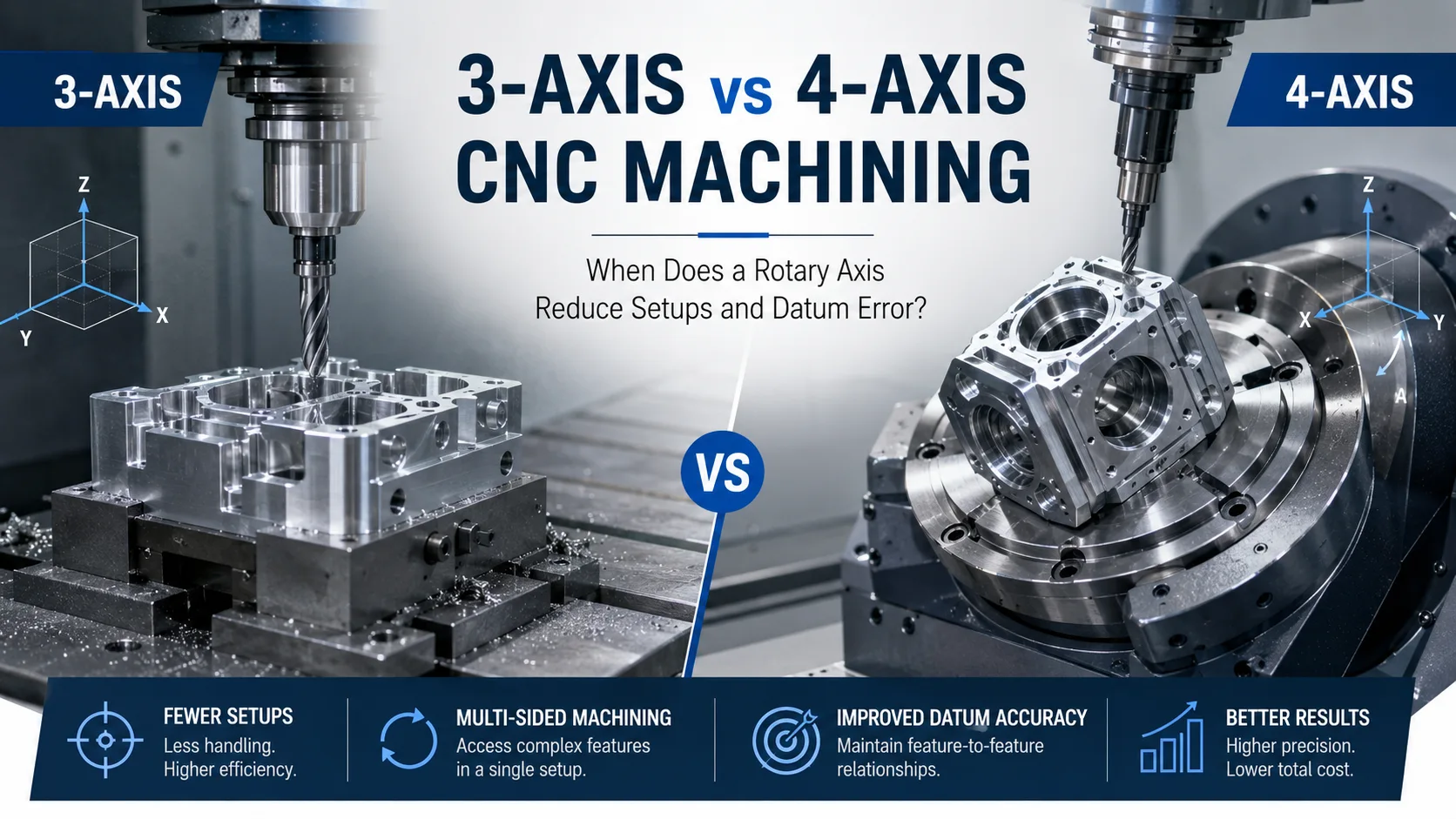
Choosing between 3-axis and 4-axis CNC machining should begin with the drawing, not the machine list. A rotary axis can expose several sides of a component without manual flipping, which may reduce fixture changes, repeated probing, and datum transfer. It does not automatically make every part more accurate or less expensive. The correct route depends on feature direction, tool access, cross-face tolerances, workholding, quantity, and inspection.
3-Axis or 4-Axis CNC Machining? Quick Decision Guide
Map every machined feature by direction, then identify which features must remain related to the same functional datum.
| Decision factor | 3-axis machining often fits | 4-axis machining often fits |
|---|---|---|
| Feature direction | One or two accessible directions | Three or more sides or radial directions |
| Cross-face relationships | Moderate or fixture-repeatable | Tight relationships around a common datum |
| Rotary features | Limited and easy to re-fixture | Radial holes, circular slots, angular patterns |
| Quantity | Prototype, low volume, changing design | Stable pilot or repeat production |
| Setup plan | One or two direct setups | Several 3-axis setups can be consolidated |
The process should be reviewed against the actual part, not specified only as “4-axis required.” Buyers can examine CK Metal Tech’s precision CNC machining capabilities when a drawing needs process review.
Choose 3-Axis Machining for Accessible, Single-Direction Features
Three-axis machining remains practical for plates, brackets, flanges, and simpler housings whose critical features are accessible from the top or one additional flipped orientation. A qualified flip fixture and probing can make a second setup repeatable enough for many drawings.
It is often more economical for prototypes, low quantities, or changing designs. Buyers should still ask how many times the part will be clamped, which datum is used, and where cross-face dimensions will be inspected.
Choose 4-Axis Machining for Multi-Sided or Rotary Features
Four-axis machining becomes more relevant when holes, slots, flats, or mounting faces are distributed around a part, or when cylindrical features require controlled angular spacing. Rotating the workpiece can give the tool access to several directions while preserving one primary clamping relationship.
Autodesk identifies multi-sided, cylindrical, and wrapped geometry as common 4-axis applications and notes that less re-clamping can reduce cumulative setup error. Undercuts or compound angles may still require 5-axis machining or another process.
How Multiple Setups Create Datum Shift and Positional Error
Re-Clamping, Re-Zeroing, and Fixture Stack-Up
Every new setup introduces variables such as debris under a locator, fixture error, clamping deformation, probe variation, work offsets, and inconsistent seating. Their combined effect can appear in features produced from different setups.
A part may pass individual checks yet fail cross-face position, perpendicularity, or center distance. Multiple setups remain acceptable when tolerance and fixture repeatability support them. Clear datums, probing, and first-article checks reduce risk.
Why 4-Axis Machining Reduces—but Does Not Eliminate—Error
Keeping the part clamped while it indexes removes some manual handling and repeated zero-setting. Autodesk describes this as a reason 4-axis machining can reduce misalignment and cumulative tolerance error.
The rotary setup still has an error chain. The workpiece must match the rotation center; the fixture must resist eccentric loading; and indexing, offsets, heat, and clamping must be controlled. Autodesk support identifies an incorrect work-coordinate position relative to the rotary center as a cause of wrong 4-axis output.
Part Geometry and GD&T Requirements That Drive Axis Selection
Multi-Sided Holes, Slots, Flats, and Mounting Features
Strong 4-axis candidates often contain features on adjacent or opposite faces that share a critical relationship. Examples include mounting holes around a housing, flats indexed at specified angles, or several faces referenced to one bore.
The drawing should identify which features control assembly. Position, perpendicularity, parallelism, and profile across faces may justify one rotary setup. If these relationships are loose, a 3-axis flip fixture may be sufficient. Buyers should mark cross-face critical dimensions and ask how each will be produced and measured.
Cylindrical, Wrapped, and Repeating Angular Features
Radial holes, circumferential grooves, engraving, and angular patterns are natural rotary-axis applications. Indexed machining positions the workpiece at defined angles; wrapped or simultaneous motion may be needed for a continuous path around a cylinder.
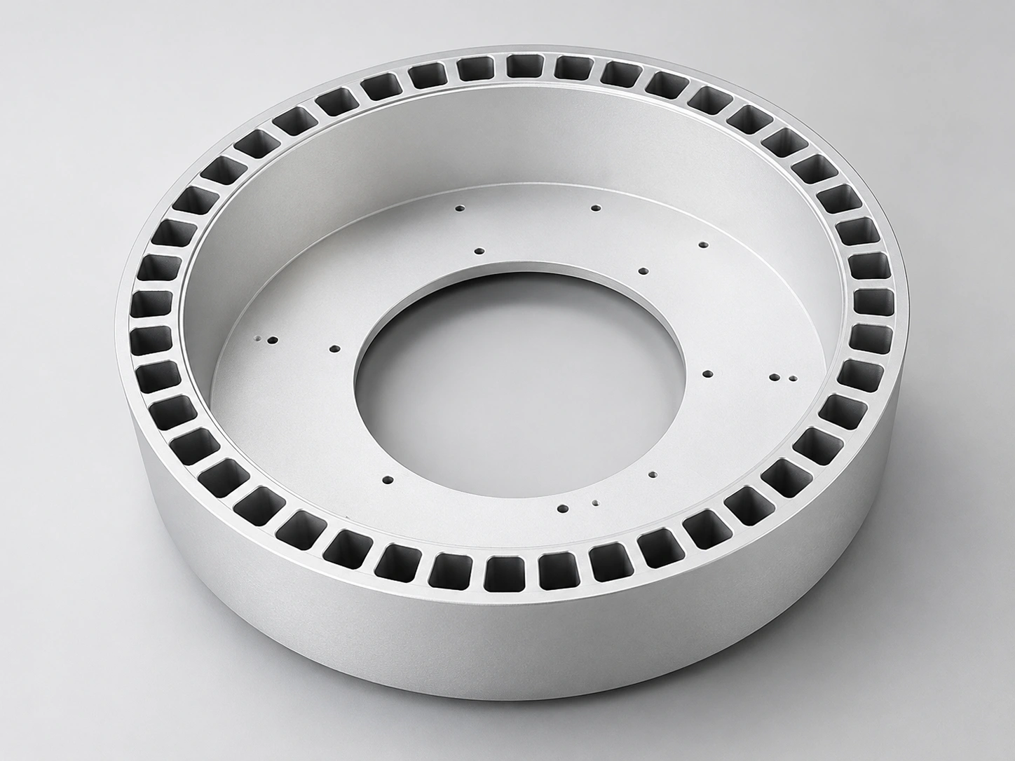
A relevant example is a four-axis CNC-machined motor housing made from high-strength aluminum alloy. Its published annular cooling grooves and mounting holes illustrate why rotary access may suit cylindrical and installation features. The page does not provide setup savings or tolerance comparisons.
Indexed 3+1 vs Simultaneous 4-Axis Machining
When Indexed 4-Axis Machining Is Sufficient
In indexed, or 3+1, machining, the rotary axis moves the part to a fixed angle and stops. Standard 3-axis toolpaths then machine that orientation. Autodesk separates this method from continuous rotary cutting.
It suits bolt patterns, radial holes, flats, pockets, and mounting features at known angles. It is generally easier to program and inspect than simultaneous motion. A quote should state indexed positions, feature groups, support, and remaining setups.
When Simultaneous Rotary Motion Is Required
Simultaneous 4-axis machining moves the rotary axis while cutting. It may fit helical grooves, wrapped contours, or free-form cylindrical surfaces that cannot be produced efficiently by fixed indexing. Autodesk notes that these workflows require rotary-orientation control, clearance planning, and collision avoidance.
The machine configuration, CAM strategy, postprocessor, rotary direction, and collision model must agree. Not every “4-axis” machine supports the same continuous strategies. Buyers should specify the required geometry rather than demand simultaneous motion by default.
3-Axis vs 4-Axis CNC Machining Cost
Compare Completed-Part Cost, Not Machine Hourly Rate
A 4-axis machine may have a higher hourly rate, but the completed part may cost less if it replaces fixtures, setups, transfers, and intermediate inspection. A simple component may cost more because of added programming, alignment, and workholding.
A fair comparison includes programming, fixtures, setup labor, cycle time, tooling, inspection, first-article approval, and rework risk. Separate one-time charges from recurring unit costs, and require the same finished scope.
Prototype, Pilot, and Repeat Production Decisions
A prototype may be produced efficiently in two 3-axis setups while the design is changing. After interfaces and quantities stabilize, a rotary fixture may become worthwhile for pilot or repeat production. The break point depends on fixture cost, setup time, inspection effort, geometry, and lifetime quantity.
Changing the route can alter datum flow, tool marks, burr location, and measurement. If prototype and production methods differ, critical characteristics need renewed pilot-run validation.
Common 4-Axis Machining Risks and How to Prevent Them
Rotary Centerline, Workholding, and Orientation Errors
If the programmed coordinate system does not match the actual rotary centerline, features can shift as the part turns. Fixture eccentricity may create changing tool engagement, vibration, and angular error. A reversed rotary direction or incorrect zero can mirror or misplace wrapped features.
Controls include probing the centerline, checking indicator readings, simulating the machine and fixture, verifying the postprocessor, and inspecting a first article at several angular positions.
Tool Access, Collision, Rigidity, and Part Deformation
Rotating the part changes the collision environment. A tool, holder, spindle, chuck, fixture, or tailstock that clears at zero degrees may interfere at another angle. Long tools may reduce rigidity and offset the benefit of fewer setups.
Thin-wall housings and long or eccentric parts can deform under rotary clamping. DFM should review clamping zones, support, tool reach, clearance, and material-removal sequence. Some features may remain safer as a separate 3-axis operation.
RFQ Checklist for a 3-Axis vs 4-Axis Process Review
Drawing, Datum, and Application Information
Provide the current 2D drawing and STEP file, material and condition, datum system, cross-face positional tolerances, angular features, cylindrical surfaces, surface requirements, and the features that control assembly. Include prototype quantity, annual demand, inspection documents, and packaging needs.
If an existing route is failing, attach its setup description, inspection report, and photographs of the nonconforming feature.
Setup, Fixture, and Inspection Questions
Ask each supplier to state:
- The proposed number of setups
- Whether the route is 3-axis, indexed 3+1, wrapped, or simultaneous 4-axis
- Which features remain in one clamping
- The rotary-axis direction and workholding concept
- Whether auxiliary support is needed
- How cross-face GD&T will be inspected
- Whether samples and production use the same route
- Which fixture and first-article charges are one-time costs
How to Choose a 3-Axis and 4-Axis CNC Machining Supplier
Verify the Process Plan, Not Only the Machine List
A machine list does not show whether a supplier can select the correct route. A useful review identifies feature directions, datum flow, tool access, fixture risk, and inspection before quotation.
Ask for a simplified setup map and the reason behind the axis selection. The supplier should recommend 3-axis machining when it is more direct and 4-axis machining when reduced handling creates an advantage. Confirm rotary-centerline and first-article controls.
Relevant CK Metal Tech Capabilities
Zhejiang Chuangkai Mechanical and Electrical Technology Co., Ltd., also known as CK Metal Tech, supports drawing-based projects through its 精密金属加工の統合能力. Confirmed resources include eight 4-axis CNC machines, four CNC milling machines, and 4-axis capacity for larger workpieces up to approximately 1.8 meters, subject to geometry, diameter, weight, fixture, and tool-access requirements.
The company also has CMM and 2.5D inspection resources and holds IATF 16949 certification. CK Metal Tech’s machining scope includes milling, turning, grinding, drilling, and related operations. Specific rotary mode, work envelope, positional capability, and inspection method should be verified against each drawing.
結論
The decision between 3-axis and 4-axis CNC machining should follow three steps: map the required machining directions, identify cross-face dimensions that depend on a common datum, and compare complete setup, fixture, programming, and inspection cost. A rotary axis can reduce re-clamping risk, but only when the centerline, workholding, program, and inspection plan are controlled.
Buyers can request a 3-axis vs 4-axis process review by submitting the drawing, STEP file, material, datum system, cross-face tolerances, circular features, quantity, and any existing setup or inspection report.
よくある質問
Does 4-axis CNC machining always improve accuracy?
No. It can reduce manual re-clamping and datum transfer, but accuracy still depends on the rotary centerline, fixture, machine condition, work offsets, toolpath, heat, and inspection method.
When is 3-axis machining more cost-effective?
It is often more economical when features are accessible from one or two directions, quantities are low, the design is changing, and cross-face tolerances can be controlled with a direct fixture.
What is the difference between 3+1 and simultaneous 4-axis machining?
In 3+1 machining, the rotary axis positions the part and remains stationary during cutting. In simultaneous machining, the rotary axis moves continuously while the tool follows the programmed path.
Can a 3-axis machine produce multi-sided parts?
Yes. The part can be flipped or moved to another fixture. Suitability depends on setup count, fixture repeatability, cross-face tolerances, quantity, and datum-transfer risk.
What information is needed for a 4-axis CNC machining quote?
Provide drawings, a STEP file, material, datums, cross-face GD&T, radial or circular features, surface requirements, quantities, application details, and inspection expectations.
返信を残す