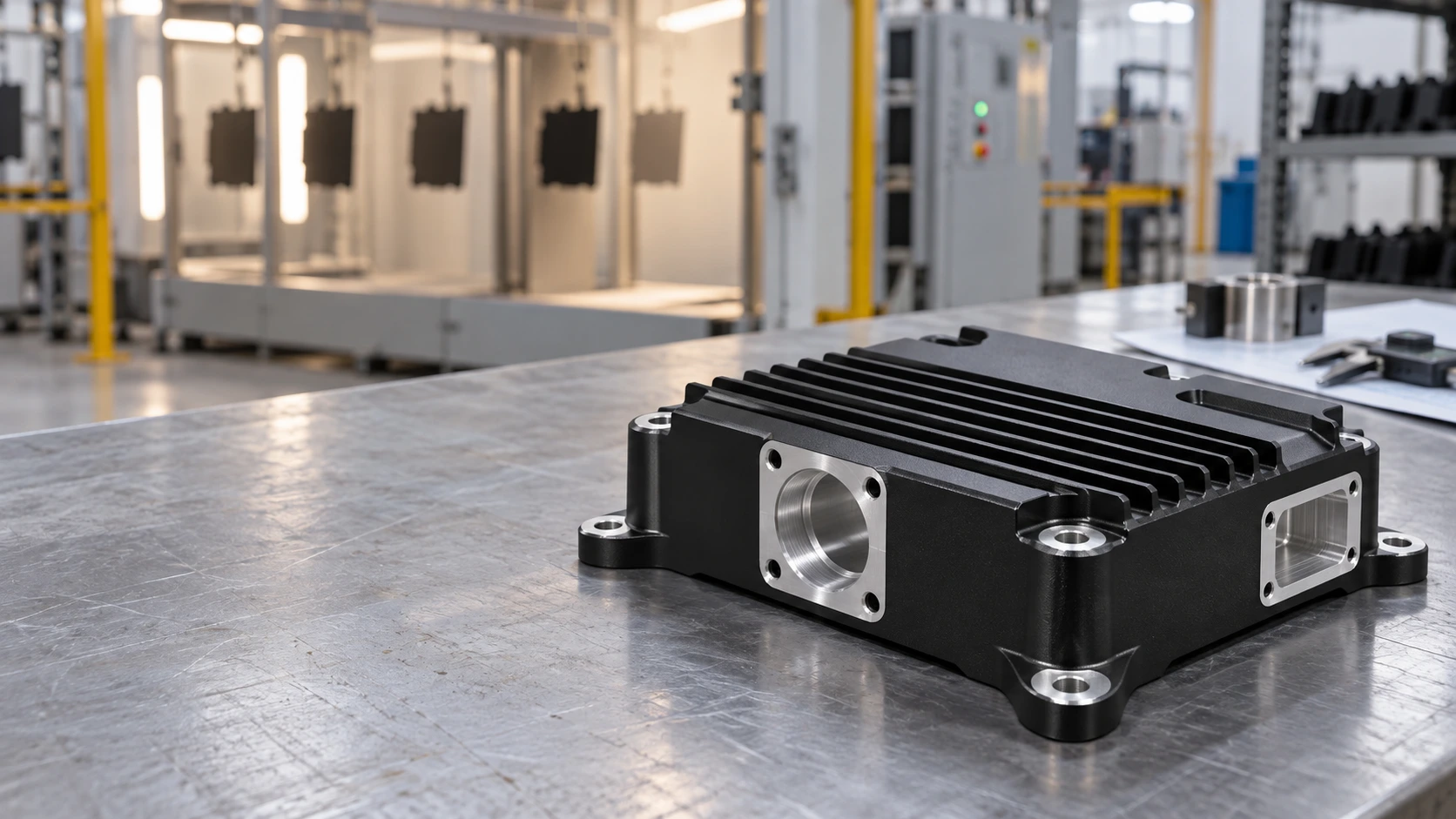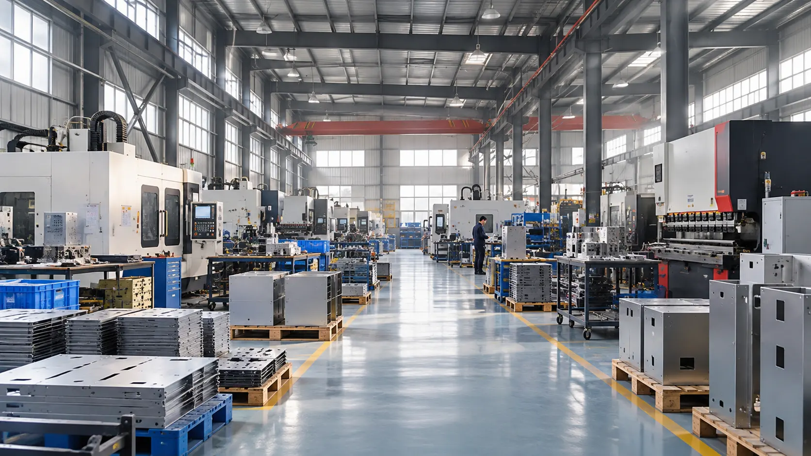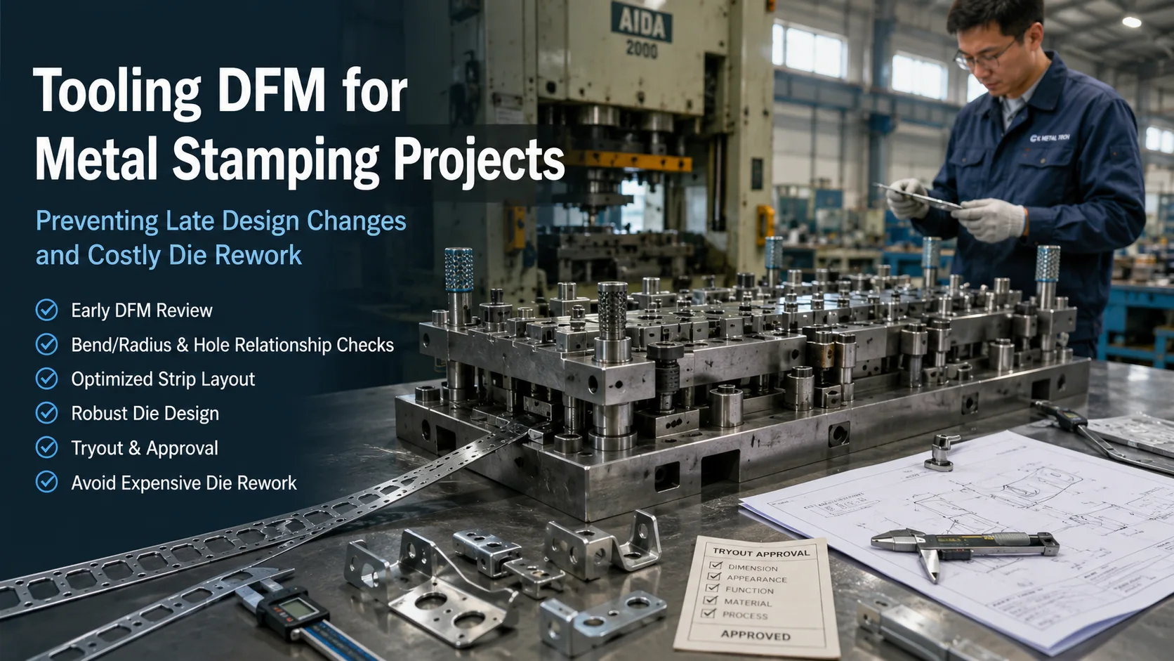
تشوانغكاي

أ أنا ل أ ن د

تحميل

     
بيت // مدونة

مدونة متخصصة في مجال الصناعة

Sheet Metal Design for AI Server Racks and Data Center Cabinets: Strength, Airflow, Cooling Integration and RFQ Checklist


Sheet Metal Design for AI Server Racks and Data Center Cabinets Strength, Airflow, Cooling Integration and RFQ Checklist

AI server rack design must connect structural strength, airflow, cooling hardware, service access, and sheet metal manufacturability before drawings are released for quotation. A cabinet may fit every listed component yet still fail if rails deflect, exhaust air recirculates, cables block the rear path, or a late-added coolant manifold interferes with removable panels. The practical goal is to convert equipment loads and cooling architecture into a buildable data center cabinet design, a testable prototype, and an RFQ that different suppliers can quote on the same basis.

Define the Rack, Cabinet, and Cooling Scope Before Designing the Sheet Metal Structure

Distinguish AI Server Racks, Data Center Cabinets, and Aisle Containment

An open rack mainly supports equipment, rails, power distribution, and cables. A cabinet adds doors, side panels, top panels, access control, and a more controlled internal air path. Aisle containment is a room-level airflow system and should not be confused with the cabinet.

Buyers should identify responsibility for rails, filters, blanking panels, PDU brackets, cable accessories, grounding hardware, and final assembly. A rack fabricator may not cover containment panels, facility ducting, or coolant distribution equipment. Without a clear boundary, suppliers may quote different products under the same description.

Translate Air-Cooled, Liquid-Ready, and Hybrid Cooling into Mechanical Requirements

An air-cooled rack needs an unobstructed inlet and exhaust route. A liquid-ready design may also require manifold brackets, hose routing, quick-connect access, drip-management provisions, and service clearance. A hybrid rack must accommodate both liquid hardware and residual air-cooled loads.

ASHRAE recommends matching cooling architecture and airflow management to AI rack density and treating power and cooling as connected design decisions. Before freezing the sheet metal geometry, confirm the cooling method, component envelopes, service direction, and responsibility for thermal validation.

Design the Structure Around the Actual Load Path

Define Static Load, Center of Gravity, Anchoring, and Transport Conditions

Total equipment weight is only the starting point. Door-mounted hardware, PDUs, cables, manifolds, rear cooling assemblies, and extended service trays can change local loading and stability. State whether the cabinet will remain fixed, move on casters, be anchored, or ship with equipment installed.

The RFQ should identify installation orientation, lifting points, floor interfaces, service extension conditions, and transport expectations. A structure suitable for stationary use may not be suitable for loaded shipment. Missing these inputs prevents a defensible decision about reinforcement, base geometry, or connection design.

Select Material, Sheet Thickness, Stiffeners, and Joint Types

Increasing sheet thickness is not the only way to raise stiffness. Folded edges, return flanges, formed ribs, localized supports, closed sections, and shorter unsupported spans may control deflection with less added mass. The right route depends on cabinet size, openings, load location, production volume, and shipping method.

Structural Route Suitable Use Main Purchasing Checks
Welded frame Fixed installation requiring rigidity Distortion, datum control, finish access
Bolted frame Modular design or shipment in sections Joint security, alignment, repeat assembly
Hybrid structure Rigid load path with removable modules Tolerance stack-up and interface control

Any thickness or reinforcement proposal should be checked against the actual load case rather than copied from a standard enclosure.

Create a Controlled Airflow Path Through the Cabinet

Design the Front-to-Rear Air Path, Doors, and Leakage Control

For front-to-rear-cooled equipment, the intake area should align with server inlets and the rear zone should remain clear. Perforated doors must balance open area with stiffness, hinge loading, security, and filtration. A universal perforation percentage is unsuitable because pressure drop depends on pattern, occupied area, equipment fans, and system configuration.

Unused rack positions and panel gaps can create bypass airflow. Define blanking requirements, door seals, side clearances, and filter arrangements. Assess the prototype as an assembled cabinet with representative doors, rails, and components, not as isolated sheet metal parts.

Prevent Recirculation, Cable Blockage, and Top-of-Rack Hot Spots

Hot exhaust can return through open rack spaces, gaps around doors, top openings, or congested rear zones. Cable bundles, PDUs, crossmembers, and cooling hoses may also restrict exhaust flow.

Blanking panels, baffles, disciplined cable routes, and clear exhaust zones can reduce cabinet-level recirculation, but they cannot correct an unsuitable room layout.


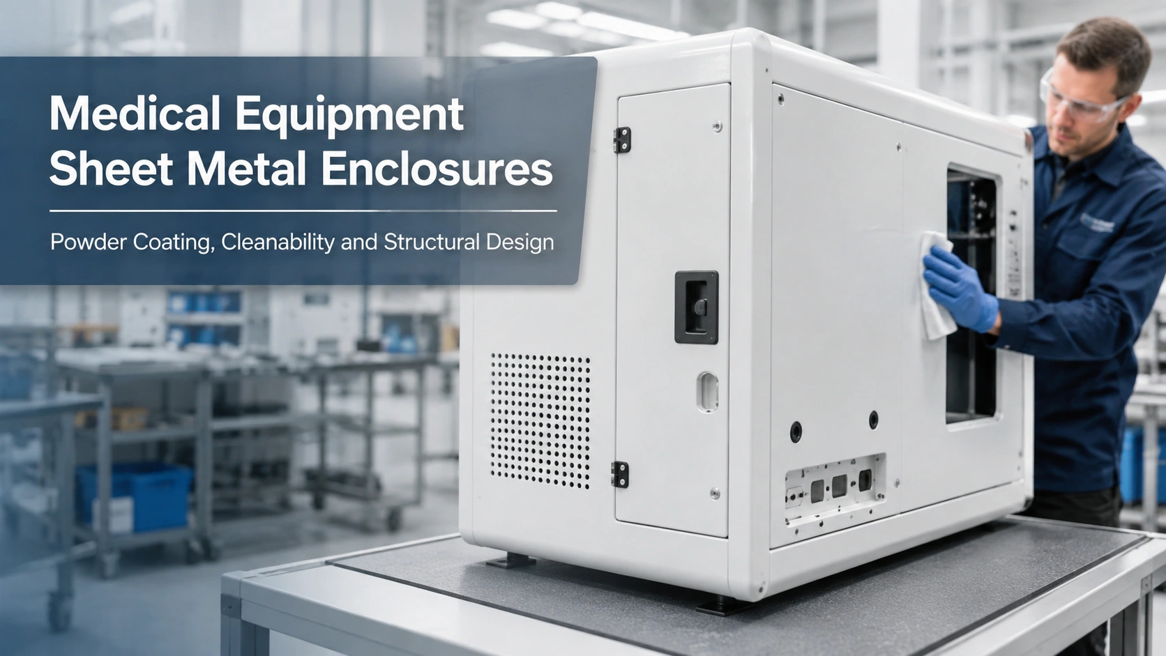
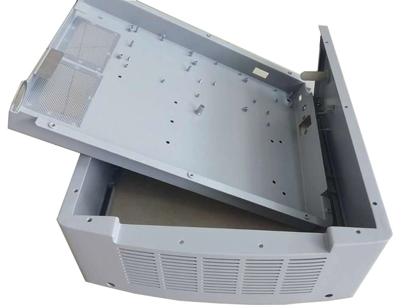
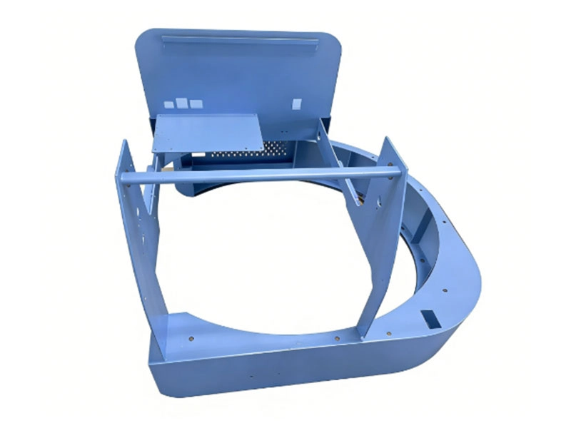
Medical and industrial equipment chassis assembly with cooling grilles and internal mounting rails

An industrial equipment chassis with cooling grilles and internal mounting rails shows how ventilation features, filters, supports, modular access, and assembly must be planned together. The referenced CK Metal Tech product serves medical, industrial testing, and communication applications, so it is a structural example rather than an AI rack performance claim.

Prepare the Cabinet for Cooling Components and Service Access

Plan Interfaces for Manifolds, Hoses, Fans, and Rear-Door Systems

A liquid-ready rack may need adjustable manifold brackets, controlled hose bend space, protected quick-connect locations, and separation between coolant paths and sensitive electrical areas. A rear-door heat exchanger or fan-assisted door may add weight to the hinge side and change rear service clearance.

Include component interface drawings, estimated weight, connection direction, removal path, and responsibility for brackets or purchased hardware. Adjustable interfaces may suit an evolving cooling system, but excessive adjustability can reduce stiffness and complicate repeat assembly.

Design Removable Panels for Maintenance, Inspection, and Replacement

Doors and panels should provide access without forcing technicians to disconnect unrelated cables or coolant lines. Review tool clearance, lifting method, panel weight, fastener retention, grounding continuity, and the sequence for removing a manifold, PDU, fan unit, or server.

More removable panels are not automatically better. Each joint can introduce alignment variation, leakage paths, and grounding requirements. Use removable construction where it supports real maintenance tasks and fixed structure where rigidity matters more.

Apply Sheet Metal DFM and Validate the Prototype

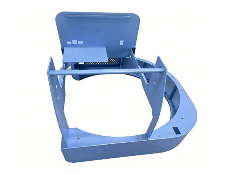
Control Bending, Welding, Fasteners, Tolerances, and Grounding Surfaces

Bend variation, weld shrinkage, hardware position, panel flatness, and coating buildup can combine into door, rail, or equipment-alignment problems. Drawings should identify functional datums, assembly-sensitive interfaces, grounding surfaces, masked threads, and dimensions that apply after finishing.

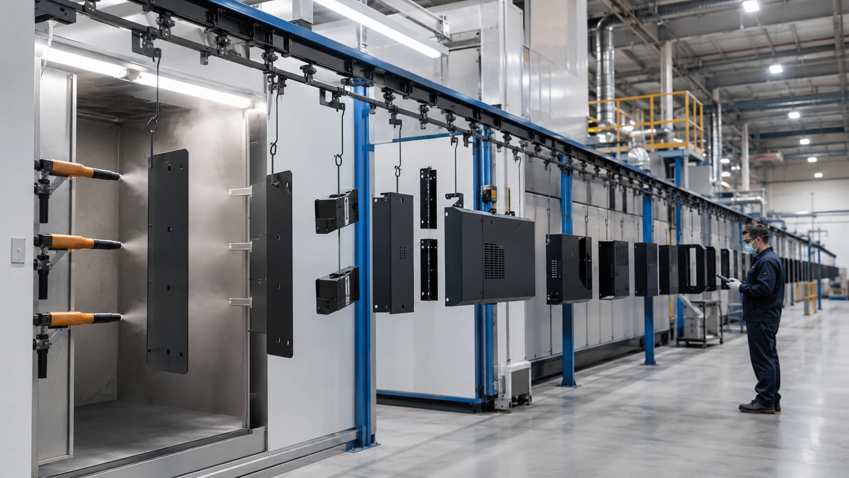
CK Metal Tech’s precision sheet metal manufacturing capabilities include CNC laser cutting, punching, bending, riveting, welding, grinding, and processing of several industrial sheet materials. Suitability depends on the drawing, dimensions, material, quantity, and inspection requirements. Buyers can also review powder coating vs wet painting for sheet metal parts when defining cosmetic areas, masking, grounding points, corrosion expectations, and assembly interfaces.

Validate Structure, Fit, Airflow, and Transport Before Repeat Production

Prototype approval should cover more than individual dimensions. A representative build may need rail alignment, door operation, panel fit, grounding continuity, equipment installation, cable routing, cooling-component clearance, and packaging review. Structural, airflow, and thermal testing responsibilities must be agreed before the order because a fabrication supplier may build to validated drawings without providing facility-level thermal engineering.

Before repeat production, freeze approved revisions, fixtures, inspection points, purchased components, packaging, and change-control rules. A successful hand-built sample does not prove repeatability without a defined production process.

Prepare the RFQ and Qualify a Sheet Metal Rack Manufacturer

Include the Technical Inputs Needed for a Comparable Quote

A custom server rack RFQ should include:

  • Controlled 2D drawings, 3D models, BOM, and revision status
  • Dimensions, equipment layout, rail interfaces, and component weights
  • Static, service, anchoring, lifting, and transport conditions
  • Air, liquid-ready, or hybrid cooling architecture
  • Door, cable, PDU, fan, filter, and manifold requirements
  • Material, finish, grounding, masking, and cosmetic specifications
  • Prototype quantity, production volume, inspection, assembly, and packaging scope

When the design is not frozen, request a DFM and prototype quotation rather than a production price based on unresolved assumptions.

Evaluate Supplier Capabilities, Evidence, and Red Flags

A qualified data center cabinet manufacturer should explain how cutting, bending, joining, finishing, inspection, trial assembly, and packaging remain controlled. Ask how functional datums are maintained, how cabinet-level fit is checked, which processes are subcontracted, and how revisions reach production.

Red flags include quotations without a revision, vague load assumptions, no review of cooling hardware, and no cabinet-level assembly check. Zhejiang Chuangkai Mechanical and Electrical Technology Co., Ltd., operating as CK Metal Tech, combines sheet metal processing, machining, stamping, surface finishing, and assembly through its قدرات تصنيع المعادن الدقيقة المتكاملة. Each AI server rack or data center cabinet still requires project-specific review.

خاتمة

A reliable AI server rack begins with a defined load path, controlled airflow, confirmed cooling interfaces, service access, and a manufacturing plan that accounts for bending, welding, hardware, finishing, and assembly. Generic sheet thickness, perforation percentages, or “liquid-ready” labels cannot replace application-specific review.

Buyers can submit drawings for a custom server cabinet manufacturing review with the 2D drawings, 3D model, BOM, dimensions, material, equipment weight, cooling configuration, target quantity, inspection scope, and packaging requirements. CK Metal Tech can then assess the requested route against its available fabrication and assembly processes.

الأسئلة الشائعة

How do I select sheet metal thickness for an AI server rack?

Thickness depends on the load path, unsupported span, openings, formed geometry, joint type, equipment weight, service conditions, and transport method. Review local deflection and interface stability rather than selecting thickness from total weight alone.

Does every AI server rack need liquid cooling?

No. The suitable architecture depends on heat output, rack density, facility conditions, server design, and operating plan. Air-cooled, liquid-ready, and hybrid configurations require different mechanical interfaces.

How can a server cabinet reduce hot-air recirculation?

Align intake and exhaust openings with the equipment, close unused rack spaces, reduce bypass gaps, keep cables and accessories out of the exhaust path, and coordinate the cabinet with aisle-level air management.

What information is needed for a custom server rack quote?

Provide drawings, BOM, dimensions, equipment layout and weight, cooling architecture, rail and accessory interfaces, material, finish, grounding, masking, quantities, inspection, assembly, and packaging requirements.

How do I choose a data center cabinet manufacturer?

Evaluate the manufacturing route, datum control, joining methods, finishing, cabinet-level assembly, inspection evidence, revision control, subcontractor management, prototype-to-production planning, and technical communication.

14th أغسطس 2026

How to Source Semiconductor Equipment Frames and Enclosures: Supplier Qualification and RFQ Checklist


How to Source Semiconductor Equipment Frames and Enclosures Supplier Qualification and RFQ Checklist

Choosing a semiconductor equipment frame supplier requires more than comparing prices. A frame or enclosure may meet individual dimensions yet still create problems when doors, rails, panels, and internal modules are assembled. Buyers must connect design intent, manufacturing route, inspection, revision control, and capacity. This guide explains how to prepare a quote-ready RFQ, qualify a semiconductor equipment enclosure manufacturer, reduce dimensional and finishing risks, and select a supplier for prototype, NPI, or repeat production.

Define the Frame and Enclosure Scope Before Sending an RFQ

Distinguish Frames, Enclosures, Chassis, and Process Chambers

A welded frame normally carries loads and establishes equipment geometry. A sheet metal enclosure protects internal components and may include doors, removable panels, ventilation features, mounting rails, cable openings, and grounding points.

Process chambers are different because vacuum, process gases, controlled atmospheres, or special cleanliness requirements may demand capabilities beyond structural fabrication. The RFQ should separate manufactured parts, purchased components, customer-supplied items, and final assembly duties, including panel fitting, hardware installation, functional checks, and module-level packaging.

This distinction prevents a common sourcing error: selecting a capable general fabricator for a component that requires application-specific sealing, cleanliness, or validation. It also prevents missing costs when a quoted frame excludes the panels, hardware, purchased items, or assembly work needed to make it usable.

Identify Functional Datums, Interfaces, Loads, and Conditions

“High precision” is not a usable purchasing specification. Engineering teams should identify the surfaces, holes, rails, and interfaces that control installation or performance. These may include base mounting points, module interfaces, door openings, grounding surfaces, and alignment features.

The suitable structure depends on size, load, stiffness, weight, corrosion exposure, service access, and finishing requirements. Welded steel, formed sheet metal, aluminum structures, machined bases, and cast iron assemblies suit different conditions. A wafer dicing equipment cast iron frame assembly, for example, should be reviewed as a combined route involving structure, machined interfaces, inspection, and assembly rather than as a generic metal part.


Wafer dicing equipment cast iron frame assembly for semiconductor equipment

Before requesting quotations, buyers should confirm which features are functional datums, which surfaces contact other modules, and whether the supplier must verify the completed assembly rather than individual components.

Build a Quote-Ready Semiconductor Equipment Enclosure RFQ

Provide Controlled Drawings, Models, BOMs, and Revisions

A useful semiconductor equipment enclosure RFQ should include current 2D drawings, 3D models when available, a BOM, revision status, material requirements, and expected quantities. The 2D drawing should control tolerances, datums, finishes, inspection notes, and special requirements.

Identify the controlling file and require the quotation to state the reviewed revision. Customer-supplied parts, standard hardware, and supplier-purchased items must be marked clearly. Otherwise, two suppliers may appear to quote the same assembly while including different materials, fasteners, finishing operations, or inspection work.

When a design is still changing, request a DFM review and prototype quotation before asking for a firm production price. This allows the supplier to identify inaccessible welds, difficult bend sequences, coating conflicts, uncertain datums, and features that may require machining after fabrication.

Specify CTQs, Finish, Inspection, Volumes, and Packaging

Critical-to-quality characteristics should relate to function. Tightening every dimension may raise cost without improving assembly, while leaving mounting interfaces undefined can make a compliant frame unusable.

State prototype quantity, batch size, annual demand, material, surface finish, cosmetic zones, masking areas, grounding points, inspection records, labeling, and packaging. The supplier should know whether dimensions apply before or after coating and which threads, electrical contact areas, locating surfaces, or slots must remain free of buildup.

Packaging also belongs in the RFQ. Large frames may require defined lifting and restraint, while finished panels need protection against rubbing, edge impact, moisture, or mixed-part contact. These details help suppliers quote comparable scopes instead of hiding different assumptions behind different unit prices.

Evaluate the Supplier’s Complete Manufacturing Route

Review Structural Fabrication and Machined Interfaces

A semiconductor equipment frame manufacturer should explain the route from raw material to approved assembly. For a welded structure, that may include cutting, fixture setup, welding sequence, intermediate checks, correction, post-weld machining where needed, surface finishing, dimensional inspection, and trial assembly.

Ask how datums are established before welding, protected during fabrication, and verified afterward. Post-weld machining may be appropriate when welding cannot reliably hold a mounting surface or hole pattern, but it is not required for every design. The decision depends on structure, tolerance, access, and risk.

Critical outsourced operations should also be disclosed. Outsourcing is not automatically unsuitable, but the main supplier should explain specification control, batch identification, incoming verification, and responsibility for nonconforming work. The quotation should cover the completed manufacturing route rather than only the processes performed in-house.

Verify Enclosure Fabrication, Finishing, and Assembly

For equipment housings, check whether the supplier can connect cutting, bending, hardware insertion, welding, grinding, finishing, and assembly. CK Metal Tech’s precision sheet metal manufacturing capabilities include laser cutting, CNC punching, bending, riveting, welding, grinding, and processing of several commonly used industrial sheet materials. Suitability still depends on the drawing, material, size, finish, and inspection plan.

Buyers should confirm when doors, panels, hinges, rails, fasteners, and internal mounting features will be trial-fitted. Features affected by coating should be reviewed before finishing. Shipping separate parts without checking the assembled condition may transfer tolerance and fit problems to the equipment builder.

Where possible, prototype approval should include representative internal components or checking fixtures. This reveals whether the enclosure functions as an assembly, not merely whether each component passes an isolated measurement.

Prevent Distortion, Misalignment, and Assembly Failures

Control Weld Distortion and Protect Functional Datums

Welding creates local heating and uneven contraction. Joint layout, material thickness, restraint, and sequence can cause twisting, bowing, or movement at mounting interfaces.

Buyers should ask how fixtures locate the structure, how the welding sequence balances heat input, and which dimensions are checked before and after finishing. First-article inspection should prioritize mounting planes, hole patterns, diagonals, rail interfaces, and features that connect to other modules.

If final correction is the main control method, ask how it affects repeatability and whether the fixture, sequence, joint design, or machining plan needs revision. Correction may produce an acceptable prototype without proving that the same route will remain stable across repeat batches.

A suitable supplier should be able to connect the drawing’s functional requirements with a practical fabrication and measurement plan.

Prevent Tolerance Stack-Up and Coating Interference

Assembly problems often result from several small deviations rather than one defective part. Bend location, bend angle, welded position, inserted hardware, hole size, and coating buildup can accumulate across an enclosure.

Doors may rub, rails may shift, modules may not align, or grounding points may become insulated. Drawings should distinguish finished dimensions from pre-coating dimensions and identify masked areas, threaded holes, contact surfaces, and assembly-sensitive slots.

Prototype approval should include fitting of doors, panels, hardware, and representative internal components where practical. For repeated interfaces, review tolerance accumulation instead of tightening every feature. Adjustment slots, locating tabs, machined references, or controlled assembly points may provide a more stable solution than imposing excessive tolerances on all sheet metal dimensions.

Verify Inspection, Traceability, and Engineering Changes

Define Evidence and Control Nonconformance

Inspection requirements should match risk. A first article may include a dimensional report, material records, finish verification, photographs, or CMM data for selected features. The RFQ should identify full-report, sampling, and functional-check requirements.

For large structures that cannot be measured in one setup, review the proposed method before production. The supplier should explain how separate measurements maintain a reliable relationship to the defined datums.

Supplier qualification should also confirm how obsolete drawings are removed, batches are identified, and deviations, substitutions, rework, or repairs receive approval. Engineering changes may affect finished inventory, work in process, purchased components, fixtures, inspection programs, and packaging documents.

SEMI describes standards as technical agreements used in purchase specifications and equipment evaluations, while traceability is an established SEMI standards subject. This supports defining project-specific documentation rather than assuming that the word “semiconductor” creates one universal inspection package.

Compare Suppliers Before Awarding the Order

A supplier that produces one acceptable prototype may not be ready for repeat production. NPI needs engineering communication and flexible planning; repeat production adds fixture control, stable inspection, capacity planning, subcontractor control, and disciplined change management. Compare the complete route, not only unit price.

Qualification Area What the Buyer Should Confirm
Application fit Similar size, material, processes, and assembly risk
Manufacturing route Clear sequence through fabrication, finishing, inspection, and packaging
Datum control Method for protecting and measuring functional interfaces
Quality evidence Appropriate first-article, material, finish, and inspection records
Change control Revision, deviation, rework, and obsolete-inventory procedures
Capacity Fit for prototype, pilot batch, and expected repeat demand
تواصل Technical contact and documented review of assumptions

Red flags include vague answers about datums, excluded critical processes, uncontrolled subcontracting, missing revision references, and no trial-assembly plan. Depending on project risk, the next step may be a technical review, supplier audit, first article, pilot batch, or production approval.

How CK Metal Tech Supports Frame and Enclosure Projects

Zhejiang Chuangkai Mechanical and Electrical Technology Co., Ltd., operating as CK Metal Tech, combines precision sheet metal processing, machining, metal stamping, surface treatment, and component assembly. Its قدرات تصنيع المعادن الدقيقة المتكاملة can support build-to-print projects requiring connected fabrication steps, and the company website lists a wafer dicing equipment cast iron frame assembly among its products.

This capability range does not replace project qualification. Buyers should submit drawings, material, functional datums, finish, target quantity, inspection requirements, and operating conditions so CK Metal Tech can review whether the requested route fits the available processes and identify points requiring clarification.

خاتمة

Successful semiconductor equipment frame sourcing starts with a controlled specification, not a supplier shortlist. Define the assembly boundary, functional datums, manufacturing route, finish, inspection evidence, change control, production stage, and packaging before comparing prices. A qualified supplier should explain how those requirements remain connected from first article through repeat production.

For a project-specific review, buyers can submit drawings and RFQ requirements to CK Metal Tech with the 2D drawing, 3D model, BOM, material, quantity, application, critical interfaces, finish, and inspection expectations. Samples or failure photographs can help focus the review.

الأسئلة الشائعة

What files are needed to quote a semiconductor equipment frame?

Provide current 2D drawings, a 3D model when available, BOM, revision, material, finish, quantities, critical datums, inspection requirements, packaging, and delivery location. Identify the controlling document and explain unresolved assumptions.

Does every semiconductor equipment enclosure require cleanroom assembly?

No. It depends on installation location, exposure to sensitive processes, customer specifications, particle risk, and downstream assembly. Cleanliness, ESD controls, packaging, and permitted residues should be stated explicitly.

What tolerances should be specified for a welded equipment frame?

Focus on mounting planes, module interfaces, hole patterns, rails, and other functional datums. Wider limits may suit nonfunctional dimensions. The supplier should review whether welding, correction, or post-weld machining can hold each requirement.

When should a welded frame be machined after welding?

Post-weld machining may be suitable when critical mounting surfaces or hole locations cannot be held consistently through fabrication and correction alone. The decision depends on frame size, stiffness, access, tolerance, material, and measurement method.

How should buyers compare semiconductor equipment enclosure suppliers?

Compare drawing review, fabrication route, datum control, finishing, trial assembly, inspection records, revision control, capacity, subcontractors, packaging, and technical communication. Confirm essential operations and documents are included.

13th أغسطس 2026

How to Control Runout in Long Shaft Machining: Setup, Grinding, and Inspection for Parts Up to 4 Meters


How to Control Runout in Long Shaft Machining Setup, Grinding, and Inspection for Parts Up to 4 Meters

Long shaft machining becomes difficult when a part passes diameter inspection but still shows excessive runout, bow, taper, vibration, or assembly misalignment. The cause may begin in the raw material, appear during stock removal, develop after heat treatment, or result from an inspection setup that does not reproduce the drawing datum. For shafts approaching four meters, material condition, workholding, machining sequence, grinding, inspection, and packaging must form one controlled process.

Long Shaft Machining Runout: Diagnose the Pattern First

Runout is commonly checked by rotating the shaft through 360 degrees and comparing the indicator’s maximum and minimum readings at a specified position. The result is meaningful only when the datum, support method, gauge position, and permitted value are defined.

Observed condition Check first Next action
Runout is concentrated near one end Center holes, chucking, tailstock, datum transfer Verify the setup axis
Maximum bow appears near the middle Support spacing, stock straightness, cutting force Review support and roughing
Diameter changes along the shaft Tailstock alignment, tool wear, thermal drift Separate geometric and thermal error
Runout increases after heat treatment Residual stress, support, remaining allowance Recheck straightness before finishing
Inspection reports disagree Datum, support points, orientation, gauge position Agree on one method

This identifies whether the next review should focus on material, setup, grinding, or measurement.

Why Long Shafts Develop Runout, Taper, and Straightness Errors

Material Straightness, Residual Stress, and Heat-Treatment Distortion

A long bar may contain initial bow or uneven residual stress. Heavy material removal can release that stress and move a shaft that appeared straight during roughing. Thin sections, keyways, and large diameter changes increase the risk.

For parts requiring substantial stock removal or heat treatment, a staged route may be safer than machining directly to final size. Rough turning establishes the geometry, followed by a stability or heat-treatment step when specified, another straightness check, and finish machining. Remaining allowance should be distributed so final turning or grinding does not need to correct most of the error from one side.

The RFQ should identify material grade, supply condition, heat treatment, hardness, and incoming straightness requirements.

Cutting Force, Unsupported Length, Clamping, and Heat

A slender shaft deflects under radial cutting force. As unsupported length increases, the tool may push the workpiece away, causing taper, barrel shape, chatter, or inconsistent diameter. Excessive chuck, tailstock, or steady-rest pressure can also bend the shaft before cutting.

Lower cutting force, short tool overhang, staged passes, controlled support, and temperature management reduce risk. A strategy that works on a rigid section may fail at the smallest diameter. Buyers should ask how the supplier will support that section, manage tool wear and thermal growth, and perform in-process checks.

Choosing the Right Setup for Long Shaft Turning

The setup should reflect shaft length, diameter, weight, material, critical datums, and permitted runout. Buyers can review CK Metal Tech’s long shaft CNC machining and grinding capabilities before submitting a drawing.

Between-Centers Turning and Tailstock Alignment

Turning between centers can preserve one rotational axis through several operations when center holes remain available as process datums. It is useful when multiple journals must relate to the same axis, although end geometry, weight, or feature access may require another setup.

Center holes must be prepared and protected because inconsistent seating transfers into runout. Tailstock alignment and thrust also matter: insufficient support permits movement, while excessive force may bow a slender shaft. The supplier should check initial indicator readings, explain how the part will be reloaded, and confirm whether center holes are temporary process features or drawing-controlled features.

Steady Rest vs. Follow Rest

A steady rest supports the shaft at a fixed position; a follow rest moves with the cutting tool. The correct choice depends on where the unsupported span develops.

Official machine guidance describes steady rests as support for long or narrow shafts and instructs operators to adjust rollers without causing workpiece deflection. It also recommends rotating the part and checking it with an indicator after adjustment.

Rollers that are too loose provide little control; rollers that are too tight can create friction, marks, heat, or artificial bending. The supplier should identify support locations and explain how alignment will be rechecked after repositioning.

Machining Sequence for Controlling Long-Shaft Runout

Rough Turning, Stability Review, and Finish Turning

A sound process separates heavy stock removal from final geometry control. Rough turning establishes the shape and reveals how the blank responds as material is removed. The shaft can then be checked for bow and datum movement before heat treatment, semi-finishing, or grinding.

A typical route is:

Material review → datum preparation → rough turning → stability or heat-treatment step → straightness review → semi-finishing → finish turning or grinding → final inspection.

The exact route depends on material, geometry, hardness, and drawing requirements. Repeated chucking should be minimized or controlled through consistent center holes, journals, or other process datums.

When Grinding Is Required—and When Turning Is Enough

Grinding may suit hardened journals, bearing fits, wear surfaces, or requirements involving surface condition, roundness, cylindricity, and relationships between diameters. It should not be added automatically. If finish turning meets the drawing, another setup may add cost and datum-transfer risk.


Precision shaft components manufactured with CNC turning and grinding processes for long shaft machining applications

For ground shafts, confirm the grinding datum, support method, allowance, heat-treatment sequence, and equipment range. CK Metal Tech’s مكونات عمود مصنعة بدقة عالية مع عملية طحن use a published route combining precision turning, grinding, and quenching for custom alloy-steel or stainless-steel designs.

This product does not establish a four-meter grinding range. Maximum length, diameter, weight, and geometry must be verified for each drawing.

How to Inspect Runout and Straightness on a Long Shaft

Define the Datum Axis Before Selecting the Gauge

Circular runout, total runout, straightness, roundness, and coaxial relationships describe different conditions. A shaft may meet diameter tolerance while failing rotational function. The drawing should identify the functional datum axis and the characteristic that affects assembly.

The datum may come from center holes, two bearing journals, or another functional feature. Measuring one section does not prove the complete shaft meets total runout or straightness requirements. Reports should state the datum, support method, gauge positions, orientation, rotation method, and result.

Control Gravity Sag and Measurement Support

A long slender shaft can sag under its own weight during horizontal inspection. Between-centers measurement, rollers, V-blocks, and coordinate measurement systems may produce different readings if support positions and datums are not correlated.

Inspection equipment must match the workpiece envelope, weight, access, and required uncertainty. A CMM may suit some features, but it should not be assumed that every machine can accommodate a complete four-meter shaft. Supplier and buyer should agree on support spacing, orientation, rotation method, and measurement correlation.

CK Metal Tech has CMM, 2.5D measurement, metallographic, and hardness-testing resources, but the method for a full-length four-meter shaft must be confirmed against the equipment range.

Troubleshooting Long-Shaft Machining Defects

Runout near one end points first to the chuck, center hole, tailstock, or datum transfer. Maximum bow near the middle suggests stock straightness, support spacing, cutting force, or stress release. Gradual taper calls for checks of alignment, tool wear, machine geometry, and temperature. Periodic chatter may indicate poor rigidity, unsuitable speed, excessive tool overhang, or unstable rest contact.

If runout increases after heat treatment, verify straightness before removing final allowance. If grinding introduces new error, review grinding heat, support pressure, wheel condition, and datum correlation. Rework should not begin until the cause and remaining allowance are understood.

RFQ Checklist for Long Shafts Up to 4 Meters

Drawing, Material, and Application Data

Provide the current 2D drawing and 3D model, total and effective machining lengths, maximum and minimum diameters, estimated weight, material grade and condition, center holes, functional datums, and all stepped, threaded, tapered, keyed, or drilled features.

State circular runout, total runout, straightness, surface requirements, heat treatment, hardness, grinding scope, and inspection records. Application details such as speed, load, mating components, and environment help identify critical features. Include quantities and any photographs or reports from an existing defect.

Capacity, Inspection, and Packaging Questions

Ask the supplier to confirm usable between-centers length, maximum diameter and weight, lifting method, tailstock and rest configuration, and which turning, heat treatment, grinding, and inspection stages are internal or outsourced. Confirm grinding range rather than assuming it matches turning capacity.

The quotation should identify datum simulation, inspection supports, sample and production setups, and packaging. A shaft that passes inspection can still bend if supported incorrectly during storage or transport.

How to Choose a Long Shaft Machining Supplier

Evaluate the Complete Manufacturing Route

A suitable supplier should explain how material review, datum preparation, roughing, support, heat treatment, finishing, grinding, inspection, and packaging connect. The review should identify where straightness is checked, how setups are repeated, which features establish the final axis, and what happens if the shaft moves after heat treatment.

Buyers should confirm whether first articles and production parts use the same route, which records are available, and how abnormal results are handled. Confirming machine length without discussing weight, support, grinding, and inspection is not a complete feasibility review.

Relevant CK Metal Tech Capabilities

Zhejiang Chuangkai Mechanical and Electrical Technology Co., Ltd. connects machining with related processes through its قدرات تصنيع المعادن الدقيقة المتكاملة. Buyers can also review نبذة عن شركة تشجيانغ تشوانغكاي للتكنولوجيا الميكانيكية والكهربائية المحدودة. when evaluating the supplier.

Confirmed resources include 18 precision CNC lathes, turning capacity for workpieces up to approximately four meters, internal and external cylindrical grinding, centerless grinding, thread rolling, tapping, and drilling. CK Metal Tech also holds IATF 16949 certification, while its website presents machining, stamping, sheet-metal fabrication, surface treatment, and assembly as connected services.

Maximum diameter, weight, grinding length, support arrangement, and achievable runout or straightness must still be verified for each project.

خاتمة

Controlling runout in long shaft machining requires more than a long-bed lathe. Material condition, datums, support pressure, cutting force, heat treatment, grinding, inspection, and transport must form one traceable route. The objective is to meet the drawing under an agreed measurement method, not to promise “zero runout.”

For a process review, submit the drawing, material, length, diameters, estimated weight, runout and straightness requirements, heat treatment, grinding scope, quantity, application, and any defect photographs or reports. Buyers can request a long shaft machining review من شركة سي كي ميتال تك.

الأسئلة الشائعة

How can runout be reduced when machining a long shaft?

Check raw-material straightness, datums, chuck and tailstock alignment, support location, cutting force, tool condition, and temperature. Separate roughing from finishing when stress release is likely, then inspect with the agreed datum and support method.

When is a steady rest required for long shaft turning?

A steady rest may be needed when the unsupported span permits deflection, vibration, or unstable size. The decision depends on diameter, length, weight, material, cutting force, geometry, and tolerance.

Should a long shaft be ground after CNC turning?

Grinding is appropriate when hardness, bearing fits, wear surfaces, roundness, cylindricity, or surface requirements cannot be met reliably by turning. It may be unnecessary when finish turning satisfies the drawing.

How is total runout measured on a four-meter shaft?

Define the datum axis, support arrangement, rotation method, and measurement locations. The method must consider gravity sag, equipment range, and correlation between supplier and customer inspection.

What information is needed for a long shaft machining quote?

Provide drawings, material condition, length, diameters, weight, datums, runout and straightness tolerances, surface requirements, heat treatment, grinding, features, quantities, application, inspection records, and packaging expectations.

7th أغسطس 2026

3-Axis vs 4-Axis CNC Machining: When Does a Rotary Axis Reduce Setups and Datum Error?


3-Axis vs 4-Axis CNC Machining When Does a Rotary Axis Reduce Setups and Datum Error

Choosing between 3-axis and 4-axis CNC machining should begin with the drawing, not the machine list. A rotary axis can expose several sides of a component without manual flipping, which may reduce fixture changes, repeated probing, and datum transfer. It does not automatically make every part more accurate or less expensive. The correct route depends on feature direction, tool access, cross-face tolerances, workholding, quantity, and inspection.

3-Axis or 4-Axis CNC Machining? Quick Decision Guide

Map every machined feature by direction, then identify which features must remain related to the same functional datum.

Decision factor 3-axis machining often fits 4-axis machining often fits
Feature direction One or two accessible directions Three or more sides or radial directions
Cross-face relationships Moderate or fixture-repeatable Tight relationships around a common datum
Rotary features Limited and easy to re-fixture Radial holes, circular slots, angular patterns
Quantity Prototype, low volume, changing design Stable pilot or repeat production
Setup plan One or two direct setups Several 3-axis setups can be consolidated

The process should be reviewed against the actual part, not specified only as “4-axis required.” Buyers can examine CK Metal Tech’s precision CNC machining capabilities when a drawing needs process review.

Choose 3-Axis Machining for Accessible, Single-Direction Features

Three-axis machining remains practical for plates, brackets, flanges, and simpler housings whose critical features are accessible from the top or one additional flipped orientation. A qualified flip fixture and probing can make a second setup repeatable enough for many drawings.

It is often more economical for prototypes, low quantities, or changing designs. Buyers should still ask how many times the part will be clamped, which datum is used, and where cross-face dimensions will be inspected.

Choose 4-Axis Machining for Multi-Sided or Rotary Features

Four-axis machining becomes more relevant when holes, slots, flats, or mounting faces are distributed around a part, or when cylindrical features require controlled angular spacing. Rotating the workpiece can give the tool access to several directions while preserving one primary clamping relationship.

Autodesk identifies multi-sided, cylindrical, and wrapped geometry as common 4-axis applications and notes that less re-clamping can reduce cumulative setup error. Undercuts or compound angles may still require 5-axis machining or another process.

How Multiple Setups Create Datum Shift and Positional Error

Re-Clamping, Re-Zeroing, and Fixture Stack-Up

Every new setup introduces variables such as debris under a locator, fixture error, clamping deformation, probe variation, work offsets, and inconsistent seating. Their combined effect can appear in features produced from different setups.

A part may pass individual checks yet fail cross-face position, perpendicularity, or center distance. Multiple setups remain acceptable when tolerance and fixture repeatability support them. Clear datums, probing, and first-article checks reduce risk.

Why 4-Axis Machining Reduces—but Does Not Eliminate—Error

Keeping the part clamped while it indexes removes some manual handling and repeated zero-setting. Autodesk describes this as a reason 4-axis machining can reduce misalignment and cumulative tolerance error.

The rotary setup still has an error chain. The workpiece must match the rotation center; the fixture must resist eccentric loading; and indexing, offsets, heat, and clamping must be controlled. Autodesk support identifies an incorrect work-coordinate position relative to the rotary center as a cause of wrong 4-axis output.

Part Geometry and GD&T Requirements That Drive Axis Selection

Multi-Sided Holes, Slots, Flats, and Mounting Features

Strong 4-axis candidates often contain features on adjacent or opposite faces that share a critical relationship. Examples include mounting holes around a housing, flats indexed at specified angles, or several faces referenced to one bore.

The drawing should identify which features control assembly. Position, perpendicularity, parallelism, and profile across faces may justify one rotary setup. If these relationships are loose, a 3-axis flip fixture may be sufficient. Buyers should mark cross-face critical dimensions and ask how each will be produced and measured.

Cylindrical, Wrapped, and Repeating Angular Features

Radial holes, circumferential grooves, engraving, and angular patterns are natural rotary-axis applications. Indexed machining positions the workpiece at defined angles; wrapped or simultaneous motion may be needed for a continuous path around a cylinder.


Four-axis CNC machined motor housing with annular cooling grooves for multi-sided machining applications

A relevant example is a four-axis CNC-machined motor housing made from high-strength aluminum alloy. Its published annular cooling grooves and mounting holes illustrate why rotary access may suit cylindrical and installation features. The page does not provide setup savings or tolerance comparisons.

Indexed 3+1 vs Simultaneous 4-Axis Machining

When Indexed 4-Axis Machining Is Sufficient

In indexed, or 3+1, machining, the rotary axis moves the part to a fixed angle and stops. Standard 3-axis toolpaths then machine that orientation. Autodesk separates this method from continuous rotary cutting.

It suits bolt patterns, radial holes, flats, pockets, and mounting features at known angles. It is generally easier to program and inspect than simultaneous motion. A quote should state indexed positions, feature groups, support, and remaining setups.

When Simultaneous Rotary Motion Is Required

Simultaneous 4-axis machining moves the rotary axis while cutting. It may fit helical grooves, wrapped contours, or free-form cylindrical surfaces that cannot be produced efficiently by fixed indexing. Autodesk notes that these workflows require rotary-orientation control, clearance planning, and collision avoidance.

The machine configuration, CAM strategy, postprocessor, rotary direction, and collision model must agree. Not every “4-axis” machine supports the same continuous strategies. Buyers should specify the required geometry rather than demand simultaneous motion by default.

3-Axis vs 4-Axis CNC Machining Cost

Compare Completed-Part Cost, Not Machine Hourly Rate

A 4-axis machine may have a higher hourly rate, but the completed part may cost less if it replaces fixtures, setups, transfers, and intermediate inspection. A simple component may cost more because of added programming, alignment, and workholding.

A fair comparison includes programming, fixtures, setup labor, cycle time, tooling, inspection, first-article approval, and rework risk. Separate one-time charges from recurring unit costs, and require the same finished scope.

Prototype, Pilot, and Repeat Production Decisions

A prototype may be produced efficiently in two 3-axis setups while the design is changing. After interfaces and quantities stabilize, a rotary fixture may become worthwhile for pilot or repeat production. The break point depends on fixture cost, setup time, inspection effort, geometry, and lifetime quantity.

Changing the route can alter datum flow, tool marks, burr location, and measurement. If prototype and production methods differ, critical characteristics need renewed pilot-run validation.

Common 4-Axis Machining Risks and How to Prevent Them

Rotary Centerline, Workholding, and Orientation Errors

If the programmed coordinate system does not match the actual rotary centerline, features can shift as the part turns. Fixture eccentricity may create changing tool engagement, vibration, and angular error. A reversed rotary direction or incorrect zero can mirror or misplace wrapped features.

Controls include probing the centerline, checking indicator readings, simulating the machine and fixture, verifying the postprocessor, and inspecting a first article at several angular positions.

Tool Access, Collision, Rigidity, and Part Deformation

Rotating the part changes the collision environment. A tool, holder, spindle, chuck, fixture, or tailstock that clears at zero degrees may interfere at another angle. Long tools may reduce rigidity and offset the benefit of fewer setups.

Thin-wall housings and long or eccentric parts can deform under rotary clamping. DFM should review clamping zones, support, tool reach, clearance, and material-removal sequence. Some features may remain safer as a separate 3-axis operation.

RFQ Checklist for a 3-Axis vs 4-Axis Process Review

Drawing, Datum, and Application Information

Provide the current 2D drawing and STEP file, material and condition, datum system, cross-face positional tolerances, angular features, cylindrical surfaces, surface requirements, and the features that control assembly. Include prototype quantity, annual demand, inspection documents, and packaging needs.

If an existing route is failing, attach its setup description, inspection report, and photographs of the nonconforming feature.

Setup, Fixture, and Inspection Questions

Ask each supplier to state:

  • The proposed number of setups
  • Whether the route is 3-axis, indexed 3+1, wrapped, or simultaneous 4-axis
  • Which features remain in one clamping
  • The rotary-axis direction and workholding concept
  • Whether auxiliary support is needed
  • How cross-face GD&T will be inspected
  • Whether samples and production use the same route
  • Which fixture and first-article charges are one-time costs

How to Choose a 3-Axis and 4-Axis CNC Machining Supplier

Verify the Process Plan, Not Only the Machine List

A machine list does not show whether a supplier can select the correct route. A useful review identifies feature directions, datum flow, tool access, fixture risk, and inspection before quotation.

Ask for a simplified setup map and the reason behind the axis selection. The supplier should recommend 3-axis machining when it is more direct and 4-axis machining when reduced handling creates an advantage. Confirm rotary-centerline and first-article controls.

Relevant CK Metal Tech Capabilities

Zhejiang Chuangkai Mechanical and Electrical Technology Co., Ltd., also known as CK Metal Tech, supports drawing-based projects through its قدرات تصنيع المعادن الدقيقة المتكاملة. Confirmed resources include eight 4-axis CNC machines, four CNC milling machines, and 4-axis capacity for larger workpieces up to approximately 1.8 meters, subject to geometry, diameter, weight, fixture, and tool-access requirements.

The company also has CMM and 2.5D inspection resources and holds IATF 16949 certification. CK Metal Tech’s machining scope includes milling, turning, grinding, drilling, and related operations. Specific rotary mode, work envelope, positional capability, and inspection method should be verified against each drawing.

خاتمة

The decision between 3-axis and 4-axis CNC machining should follow three steps: map the required machining directions, identify cross-face dimensions that depend on a common datum, and compare complete setup, fixture, programming, and inspection cost. A rotary axis can reduce re-clamping risk, but only when the centerline, workholding, program, and inspection plan are controlled.

Buyers can request a 3-axis vs 4-axis process review by submitting the drawing, STEP file, material, datum system, cross-face tolerances, circular features, quantity, and any existing setup or inspection report.

الأسئلة الشائعة

Does 4-axis CNC machining always improve accuracy?

No. It can reduce manual re-clamping and datum transfer, but accuracy still depends on the rotary centerline, fixture, machine condition, work offsets, toolpath, heat, and inspection method.

When is 3-axis machining more cost-effective?

It is often more economical when features are accessible from one or two directions, quantities are low, the design is changing, and cross-face tolerances can be controlled with a direct fixture.

What is the difference between 3+1 and simultaneous 4-axis machining?

In 3+1 machining, the rotary axis positions the part and remains stationary during cutting. In simultaneous machining, the rotary axis moves continuously while the tool follows the programmed path.

Can a 3-axis machine produce multi-sided parts?

Yes. The part can be flipped or moved to another fixture. Suitability depends on setup count, fixture repeatability, cross-face tolerances, quantity, and datum-transfer risk.

What information is needed for a 4-axis CNC machining quote?

Provide drawings, a STEP file, material, datums, cross-face GD&T, radial or circular features, surface requirements, quantities, application details, and inspection expectations.

6th أغسطس 2026

مقارنة بين التصنيع السويسري والتشغيل باستخدام الحاسوب (CNC): كيفية الاختيار للأعمدة الصغيرة والدبابيس والأجزاء النحيفة

مقارنة بين التصنيع السويسري والتشغيل باستخدام الحاسوب (CNC): كيفية الاختيار للأعمدة الصغيرة والدبابيس والأجزاء النحيفة


يصبح الاختيار بين التصنيع باستخدام آلات سويسرية أو الخراطة التقليدية باستخدام الحاسوب (CNC) صعبًا عندما يحتوي الرسم على قطر صغير، أو مقطع طويل غير مدعوم، أو متطلبات دقيقة للدقة، أو ميزات ثانوية. يعتمد الخيار على الدعم، وطول القطع، وحالة الخامة، وتعقيد الميزة، والتفاوتات المسموح بها، والكمية. يساعد هذا الدليل المهندسين وفرق التوريد على تقييم الأعمدة، والدبابيس، والأكمام، والموصلات، وغيرها من الأجزاء النحيفة دون الاعتماد على قاعدة ثابتة.

التشغيل الآلي السويسري أم الخراطة باستخدام الحاسوب؟ دليل الاختيار السريع

ينبغي أن يستند القرار الأول إلى الهندسة ومخاطر العملية، وليس إلى افتراض أن الآلة السويسرية أكثر دقة. يمكن للمشترين مراجعة منتجات شركة CK Metal Tech. قدرات الخراطة الدقيقة باستخدام الحاسوب (CNC) والتشغيل السويسري عندما يحتاج كلا المسارين إلى التقييم.

شروط المشروع غالباً ما تكون عمليات التشغيل السويسرية مناسبة غالبًا ما تكون عملية الخراطة التقليدية باستخدام الحاسوب مناسبة
قطر صغير مع قسم طويل ونحيف يمكن أن يبقى الدعم قريبًا من منطقة القطع ممكن إذا تم التحكم في انحراف استراتيجية تثبيت وقطع العمل
جزء قصير وصلب وبسيط قد يؤدي ذلك إلى إضافة إعدادات غير ضرورية غالباً ما يكون الطريق الأكثر مباشرة
ثقوب متقاطعة، أسطح مستوية، أخاديد، أو أعمال خلفية مفيد عندما تجمع الآلة بين العمليات يُعدّ هذا الأمر عمليًا عندما يظل العمل الثانوي اقتصاديًا.
حجم منخفض أو غير مؤكد يعتمد ذلك على الإعدادات والميزات غالباً ما يكون تبريره أسهل
إنتاج متكرر مستقر يمكن أن يقلل من عمليات المناولة بين العمليات تنافسية من أجل هندسة أبسط
استقامة القضيب أو قطره المتغير يجب أن تتناسب القطعة الأصلية مع جلبة التوجيه قد تكون أقل حساسية، وذلك يعتمد على طريقة تثبيت قطعة العمل.

اختر التصنيع السويسري للأجزاء ذات الأقطار الصغيرة، والرفيعة، ومتعددة الميزات

تُعتبر عملية التصنيع السويسرية شائعة الاستخدام عندما ينحني أحد المكونات أو يهتز أثناء ابتعاد الأداة عن نقطة التثبيت الرئيسية. في عملية التوجيه باستخدام الجلبة، يتم تثبيت القضيب بالقرب من منطقة القطع بينما يقوم رأس المخرطة بتغذية المادة عبر الدليل. هذا يقلل من طول الجزء غير المدعوم أثناء القطع، وهو مناسب للدبابيس الدقيقة الطويلة، والأعمدة المتدرجة الضيقة، والأجزاء الحساسة.

يُعدّ هذا النوع من المخارط مفيدًا أيضًا عند دمج عمليات الخراطة، والحفر العرضي، والتفريز، والتشكيل اللولبي، أو التشكيل الخلفي. يجب على المشترين التحقق من مواصفات الماكينة الفعلية. قد تعمل المخرطة السويسرية مع أو بدون جلبة توجيه، بينما تختلف الأدوات الدوارة، ووظائف المغزل الفرعي، وأحجام القضبان القابلة للاستخدام. تؤكد المواصفات المنشورة أن المخارط السويسرية القابلة للتحويل تدعم كلاً من التشغيل باستخدام جلبة التوجيه والتشغيل باستخدام نظام التثبيت.

اختر الخراطة التقليدية باستخدام الحاسوب (CNC) للأجزاء الأقصر أو الأكبر أو الأبسط

لا تزال عملية الخراطة التقليدية باستخدام الحاسوب (CNC) عمليةً مناسبةً للأجزاء الصلبة، والملامح الخارجية البسيطة، والأقطار الكبيرة، والكميات الصغيرة، أو الرسومات التي يُحتمل تغييرها. أما بالنسبة للدبابيس القصيرة ذات القطر الواحد والخيوط الأساسية، فقد لا يكون استخدام نظام الخراطة السويسرية مُبرراً.

يمكن لمخرطة ذات رأس ثابت إنتاج أجزاء رفيعة باستخدام دعامة الذيل، ودعامات ثابتة، وقطع مُجزأ، وأدوات ذات قوة منخفضة. السؤال هو ما إذا كانت هذه الإجراءات تُنتج أجزاءً مستقرة. إن تكرار التصحيحات، أو الحاجة إلى عدة عمليات ضبط، أو عدم انتظام الانحراف، كلها أمور تستدعي إعادة النظر في عمليات التشغيل السويسرية. إذا ظل الجزء مستقرًا، فقد يؤدي تغيير المعدات إلى زيادة التكلفة دون تحسين الأداء.

لماذا يؤثر دعم قطعة العمل على دقة الأجزاء النحيفة

دعم جلبة التوجيه مقابل تثبيت قطعة العمل برأس المخرطة الثابت

ينحرف العمود النحيف عند تعرض جزء غير مدعوم لقوة قطع شعاعية. وقد ينتج عن ذلك تناقص في القطر، أو اهتزاز، أو تغير في القطر، أو عدم استقامة، أو سطح غير متجانس. ويزداد الخطر عندما يكون الجزء الأضعف بعيدًا عن ظرف التثبيت أو يحتوي على إجهاد متبقٍ.

يقلل جلبة التوجيه المسافة بين الأداة والدعامة، لكنها لا تزيل تآكل الأداة، أو الحرارة، أو تفاوت الخامة، أو الخلوص، أو مشاكل التسلسل. قد يظل الخراطة التقليدية مناسبًا عند استخدام دعامة خلفية أو مسند ثابت لدعم القطعة دون وجود عوائق. ينبغي على المشترين الاستفسار عن كيفية تثبيت قطعة العمل وما إذا كان الإنتاج يستخدم نفس الإعداد.

استقامة قضيب الخام، وتفاوت القطر، وملاءمة جلبة التوجيه

في عملية تشكيل جلبة التوجيه، يؤثر قطر القضيب واستدارته واستقامته وحالة سطحه على التغذية والتلامس. قد يؤدي الخلوص الزائد إلى إضعاف الدعم، بينما قد يتسبب الخلوص غير الكافي في الاحتكاك أو مشاكل التغذية أو علامات على السطح.

تعتمد متطلبات المخزون على الماكينة والمادة والهندسة وطريقة التشغيل. يمكن لبعض المخارط السويسرية القابلة للتحويل العمل بدون جلبة توجيه واستخدام قضبان مسحوبة للأجزاء القصيرة، بينما قد تتطلب أعمال جلبة التوجيه مخزونًا أكثر تحكمًا. تُفرّق معلومات TSugami SS20 بين عملية جلبة التوجيه التقليدية وعملية التثبيت الاختيارية، مما يُبيّن سبب ضرورة ذكر حالة المادة في طلب عرض الأسعار بدلاً من درجة السبيكة فقط.

كيف تحدد هندسة القطعة والتفاوتات عملية الخراطة الصحيحة

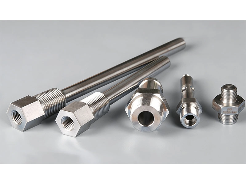
مكونات أعمدة دقيقة مصنعة باستخدام عمليات الخراطة والطحن والمعالجة الحرارية باستخدام الحاسوب (CNC) للتطبيقات الصناعية


قم بتقييم القطر والطول الفعال ونسبة الطول إلى القطر معًا

نسبة الطول إلى القطر مفيدة، ولكن لا يوجد حدٌّ فاصلٌ عامٌّ يناسب جميع الأجزاء. قد يكون الطول الحرج هو الجزء المُشَكَّل آليًا وليس الطول الكلي. في العمود المُدرَّج، قد يكون أصغر قطر أو أطول جزء ضعيف هو العامل المُتحكِّم في الانحراف.

راجع معًا الحد الأدنى للقطر، وطول القطع غير المدعوم، ونصف قطر الانتقال، وسماكة الجدار، وصلابة المادة، وإمكانية الوصول إلى الأداة. قد يختلف سلوك الغلاف المجوف عن سلوك الدبوس الصلب ذي الأبعاد الخارجية نفسها. حدد نقاطًا مرجعية ومقاطعًا حيث يؤثر الانحناء أو التناقص على التجميع، ثم قارن بين الدعم، وتسلسل القطع، وإمكانية التجليخ.

مراجعة الانحراف، والاستقامة، وجودة السطح

لا يحدد تفاوت القطر أداء العمود بشكل كامل. يؤثر الانحراف المحوري على الأسطح الدوارة، وتؤثر الاستقامة على المحاذاة، ويمكن أن تؤثر حالة السطح على المحامل أو موانع التسرب أو التلامس الانزلاقي.

اربط كل متطلب بالوظيفة وحدد كيفية قياسه. قد تُنتج عملية الخراطة الشكل النهائي مباشرةً، لكن بعض المكونات تتطلب طحنًا أسطوانيًا أو طحنًا بدون مركز بعد الخراطة أو المعالجة الحرارية. (CK Metal Tech) مكونات عمود مصنعة بدقة عالية مع عملية طحن يوضح هذا الشكل مسارًا يجمع بين الخراطة الدقيقة والطحن والتبريد السريع لتصميمات الأعمدة المخصصة المستخدمة في الآلات وتطبيقات النقل.

افحص الثقوب المتقاطعة، والأسطح المستوية، والأخاديد، والخيوط، والتشكيل الخلفي

غالباً ما تصبح الأجزاء الصغيرة باهظة الثمن لأنها تتطلب عمليات متعددة. قد تتطلب الثقوب المتقاطعة، والأسطح المستوية، والشقوق، والخيوط، وحفر الأطراف، وميزات القطع الجانبية معالجة ثانوية.

قد تُنجز آلة سويسرية مُجهزة بشكل مناسب عدة وظائف في دورة واحدة باستخدام أدوات دوارة ومغزل فرعي. هذا من شأنه أن يقلل من عمليات النقل وتغييرات نقطة الإسناد، ولكن قد تظل عمليات إزالة النتوءات أو التجليخ أو المعالجة الحرارية قادرة على التحكم في التكلفة. اطلب من المورد تحديد كل عملية ونقطة إسناد ومرحلة فحص. قارن مسارات الأجزاء المُنجزة، وليس أوقات الدورات فقط.

مقارنة بين تكلفة وحجم إنتاج الخراطة السويسرية والخراطة باستخدام الحاسوب

قارن تكلفة الإعداد بتكلفة الجزء المكتمل

قد تتطلب عمليات التشغيل السويسرية تجهيز القضبان، واختيار جلبة التوجيه، واستخدام أدوات إضافية، وبرمجة دقيقة. أما عمليات الخراطة التقليدية فقد تكون أقل تكلفةً في الإعداد، ولكنها تتطلب عمليات حفر، وتفريز، وإزالة نتوءات، أو تشكيل خلفي منفصلة.

تشمل المقارنة العادلة المواد، والإعداد، ووقت الدورة، والأدوات، وفقدان المواد المتبقية، والعمليات الثانوية، والطحن، والمعالجة الحرارية، والتشطيب، والفحص، والتغليف. تأكد من أن العينات والإنتاج يستخدمان نفس العملية. لا يُجدي سعر النموذج الأولي المنخفض نفعًا إذا تطلب الإنتاج لاحقًا مسارًا جديدًا.

اختر العملية عبر مراحل النموذج الأولي والتجريب والإنتاج المتكرر

قد يستخدم النموذج الأولي الخراطة التقليدية أثناء إجراء التغييرات في التصميم. بعد استقرار الشكل الهندسي والطلب، قد تصبح المعالجة السويسرية خيارًا جذابًا إذا جمعت بين العمليات وقللت من عمليات المناولة. مع ذلك، قد يظل نظام المعالجة السويسرية المعقد غير اقتصادي في حالة انخفاض الطلب المتكرر.

قارن بين سيناريوهات الكميات المنخفضة والمتوقعة والعالية، مع فصل التكاليف لمرة واحدة عن التكاليف المتكررة. ضع في اعتبارك ما إذا كان تغيير العملية يؤثر على موقع النتوءات، أو علامات الأدوات، أو نقاط المرجعية، أو القدرة الإنتاجية. يقلل وضع خطة مرحلية - تشمل التحقق من صحة التصميم، ومراجعة العملية، والدفعة التجريبية، ثم الموافقة على الإنتاج - من المخاطر.

مشاكل شائعة في الانعطاف وكيفية تجنبها

التناقص التدريجي، والاهتزاز، والانحراف، وضعف الاستقامة

لا تُثبت هذه العيوب بالضرورة اختيار آلة خاطئة. قد ينتج التناقص التدريجي عن الانحراف أو التآكل أو الحرارة أو عدم المحاذاة. وقد ينجم الاهتزاز عن عدم كفاية الصلابة أو استخدام أدوات غير مناسبة أو ظروف تشغيل قاسية أو طول غير مدعوم زائد. وقد يبدأ ضعف الاستقامة في القضيب نفسه، أو الإجهاد المتبقي، أو المعالجة الحرارية، أو تسلسل القطع.

قدّم للمورد قياسات توضح موضع الانحراف، وتاريخ الفحص، ومعلومات الدفعة، ورقم دفعة المواد، وما إذا كانت المشكلة تظهر تدريجيًا أم بشكل عشوائي. قد يُبرر استمرار عدم الاستقرار بعد مراجعة الدعم والأدوات والمعايير استخدامَ التشغيل الآلي السويسري أو التجليخ.

علامات جلبة التوجيه، واختلاف القضيب، والنتوءات، وبقايا النفايات

تنطوي عملية التصنيع السويسرية على مخاطرها الخاصة. فقد يؤدي احتكاك الجلبة إلى ترك علامات على أسطح القضبان غير المناسبة، وقد تترك الثقوب العرضية نتوءات حساسة للتجميع، ويمكن أن تؤثر البقايا على تكلفة الإنتاج على المدى القصير.

قبل الموافقة، حدد خصائص الأسطح التجميلية، وحدود النتوءات، وفواصل الحواف، وشروط القطع، والتغليف. تأكد من مورد القضيب وحالة المخزون المطلوبة. تمنع هذه التفاصيل فشل القطعة ذات الأبعاد المقبولة في تلبية متطلبات التجميع أو المناولة.

قائمة التحقق من طلبات عروض الأسعار للأعمدة الصغيرة والدبابيس والأجزاء النحيفة

يتضمن عرض الأسعار المفيد الرسم ثنائي الأبعاد الحالي وملف STEP، والمادة وحالتها، وأطوال القطع الكلية والفعالة، والأقطار القصوى والدنيا، والتفاوتات البعدية والهندسية، ومتطلبات السطح، والميزات، والمعالجة الحرارية، والتشطيب، والكميات.

حدد أيضًا سجلات الفحص، وكمية العينات، والطلب السنوي، والتطبيق، والتغليف. قد تحتاج الأجزاء الطويلة إلى حماية من الانحناء أثناء النقل. استفسر عما إذا كانت عمليات الطحن، ودرفلة الخيوط، وإزالة النتوءات، والمعالجة الحرارية، والتشطيب مشمولة، وحدد الافتراضات المتعلقة بالمخزون أو العمليات الخارجية.

كيفية اختيار مورد سويسري لتصنيع وتشكيل المعادن باستخدام الحاسوب

ينبغي على المورّد أن يشرح سبب ملاءمة العملية. استفسر عن نطاق الآلات، وطريقة التشغيل، وأنظمة تثبيت القطع، والأدوات المتحركة، والتشكيل الخلفي، والعمليات الثانوية، والفحص، وضوابط تآكل الأدوات وتفاوت المواد الخام. لا تختر مورّدًا لمجرد ظهور عبارة "التصنيع السويسري" في قائمة قدراته.

تدعم شركة تشجيانغ تشوانغكاي للتكنولوجيا الميكانيكية والكهربائية المحدودة مشاريع تصنيع الأجزاء بالخراطة باستخدام مخرطة سويسرية خماسية المحاور، و18 مخرطة CNC دقيقة، بالإضافة إلى موارد الطحن الأسطواني الداخلي والخارجي، والطحن بدون مركز، ودرفلة الخيوط، والتثقيب، والحفر. قدرات تصنيع المعادن الدقيقة المتكاملة تغطي هذه الوثيقة عمليات التصنيع والتجميع المتصلة. ويمكن للمشترين أيضاً مراجعة هذه الوثيقة. نبذة عن شركة تشجيانغ تشوانغكاي للتكنولوجيا الميكانيكية والكهربائية المحدودة. عند تقييم خلفيتها، تُدرج شركة CK Metal Tech الخراطة باستخدام الحاسوب والتشغيل الآلي السويسري ضمن خدماتها، وهي حاصلة على شهادة IATF 16949.

خاتمة

تُعدّ عمليات التشغيل السويسرية مناسبةً في كثير من الأحيان للأجزاء الصغيرة القطر، والرفيعة، والمتعددة الخصائص، حيث يُسهم الدعم بالقرب من منطقة القطع والعمليات المُدمجة في تقليل مخاطر الجودة والتعامل. بينما تبقى عمليات الخراطة التقليدية باستخدام الحاسوب (CNC) عمليةً للأجزاء الأقصر، والصلبة، والأبسط، أو ذات الكميات المنخفضة. ينبغي أن يتبع الاختيار مسار التصنيع النهائي، وليس قطرًا أو نسبةً أو كميةً ثابتة.

لإجراء مراجعة للعملية، يُرجى تقديم الرسم، والمادة، والأقطار، والطول الفعال، والتفاوتات الحرجة، والميزات، والمعالجة الحرارية، والكمية المستهدفة، والتطبيق، وأي صور أو عينات للعيوب. يمكن للمشترين اطلب مراجعة لتصنيع الأعمدة والدبابيس من شركة سي كي ميتال تك.

الأسئلة الشائعة

ما هو الفرق الرئيسي بين التشغيل الآلي السويسري والتشغيل الآلي باستخدام الحاسوب (CNC)؟

تستطيع آلات الخراطة السويسرية تثبيت قضبان الخام بالقرب من نقطة القطع باستخدام جلبة توجيه، بينما تعتمد آلات الخراطة التقليدية عادةً على تثبيت قطعة العمل برأس ثابت. كما يمكن لبعض الآلات السويسرية العمل بدون جلبة توجيه.

متى يجب استخدام التصنيع السويسري للأعمدة النحيفة؟

ضع في اعتبارك أن الانحراف أو الاهتزاز أو التناقص التدريجي أو العديد من الخصائص الثانوية تجعل عملية الخراطة التقليدية غير مستقرة أو مكلفة. راجع الحد الأدنى للقطر، والطول الفعال، والمادة، والتفاوتات، والخصائص، والكمية بدلاً من الاعتماد على نسبة واحدة.

هل تُعدّ عمليات التشغيل السويسرية أغلى من عمليات الخراطة التقليدية باستخدام الحاسوب؟

قد يكون الإعداد أكثر تعقيدًا، لكن الجمع بين الخراطة والحفر والتفريز والتشكيل الخلفي يمكن أن يقلل من تكلفة القطعة النهائية في الإنتاج المتكرر. قد تظل القطع البسيطة أو ذات الكميات المنخفضة أقل تكلفة على المخرطة التقليدية.

هل يمكن لمخرطة CNC تقليدية أن تصنع دبابيس طويلة ودقيقة؟

نعم، يعتمد ذلك على القطر والمادة والتفاوتات والدعم والأدوات واستراتيجية القطع. قد يُفضّل استخدام طريقة التشغيل السويسرية في حالة الانحراف المستمر أو المعالجة الثانوية المفرطة.

ما هي المعلومات المطلوبة للحصول على عرض أسعار لخدمات التشغيل الآلي السويسرية؟

يرجى تقديم الرسومات والمواد والحالة والأقطار والطول الفعال والتفاوتات والانحراف والاستقامة ومتطلبات السطح والميزات والمعالجة الحرارية والتشطيب ونطاق الفحص والتعبئة والتغليف والكميات.

31st يوليو 2026

التصنيع باستخدام الحاسوب مقابل تشكيل المعادن بالختم: متى يكون استخدام أدوات الختم مجديًا؟


التصنيع باستخدام الحاسوب مقابل تشكيل المعادن بالضغط: متى يكون استخدام أدوات التشكيل بالضغط مجديًا؟

لا يقتصر اختيار التصنيع باستخدام الحاسوب (CNC) أو تشكيل المعادن بالختم على مجرد سعر الوحدة. السؤال الحقيقي هو ما إذا كانت هندسة القطعة، ونضج تصميمها، وحجم الإنتاج المتوقع، والطلب عليها طوال عمرها الافتراضي تبرر استخدام قالب ختم مخصص. غالبًا ما يكون التصنيع باستخدام الحاسوب أكثر أمانًا للنماذج الأولية، والطلب غير المؤكد، والقطع ذات الشكل الصلب (قضيب أو كتلة)، والقطع التي يُحتمل تغييرها. يصبح تشكيل المعادن بالختم أكثر جاذبية عندما يتكرر تصميم الصفائح المعدنية المستقر لفترة كافية لتوزيع استثمار الأدوات على القطع النهائية. في بعض الحالات، يكون الحل الأقل مخاطرة هو اتباع نهج هجين: ختم الشكل الهندسي الأساسي، ثم تصنيع الميزات الأساسية فقط.

التصنيع باستخدام الحاسوب، أو تشكيل المعادن بالضغط، أو عملية هجينة؟

شروط المشروع التصنيع باستخدام الحاسوب (CNC) تشكيل المعادن المسار الهجين
من المرجح حدوث تغييرات في التصميم ملاءمة قوية مخاطر عالية في الأدوات ممكن بعد تجميد جزئي للتصميم
الطلب غير مؤكد ملاءمة قوية يصعب تبريره مفيد في صناعة الجسور
حجم تكرار ثابت مراجعة تكلفة دورة الحياة مرشح قوي مرشح قوي
شكل قضيب صلب أو كتلة هندسية ملاءمة قوية غير مناسب عادة محدود
هندسة الصفائح أو اللفائف ممكن مرشح قوي مرشح قوي
ثقوب دقيقة، أو خيوط، أو أسطح مرجعية ملاءمة قوية قد يحتاج إلى أعمال إضافية غالباً ما يكون عملياً

استمر في استخدام آلات CNC عندما يكون حجم الإنتاج أو التصميم غير مؤكد

تُعدّ عمليات التصنيع باستخدام الحاسوب (CNC) مناسبة عادةً أثناء اختبار المشروع لوظيفته، وملاءمته، وتلبية الطلب، أو الوصول إلى الشكل الهندسي النهائي. فهي تقبل التعديلات دون الحاجة إلى قالب إنتاج مخصص، ويمكنها إنشاء ميزات معقدة من ألواح أو قضبان أو كتل معدنية. وهذا ما يجعل خدمات التصنيع الدقيق باستخدام الحاسوب (CNC) مناسب للنماذج الأولية، والتشغيل التجريبي، وقطع الغيار، والطلبات المتكررة التي لا تدعم أحجامها بعد استهلاك تكاليف الأدوات.

تأكد من برمجة المكونات، والتجهيزات، وإنتاجية المواد، وتسعير الدفعات، والفحص، وتكاليف المراجعة. قد تصبح عمليات التشغيل الآلي مكلفة عندما يتطلب كل جزء وقت دورة طويل أو يزيل كمية كبيرة من المادة الأولية. ومع ذلك، قد تظل صحيحة عندما يتعذر تشكيل الشكل الهندسي من الصفائح، بغض النظر عن الكمية.

استثمر في أدوات التشكيل بالضغط عندما تكون الهندسة والطلب والتصميم مستقرة.

تصبح أدوات الإنتاج عملية عندما يمكن تشكيل أو ثقب أو ثني أو تشكيل أو سحب أحد المكونات من مادة مسطحة، ويكون من غير المرجح أن تتغير. تتطلب القوالب تكلفة أولية، ولكن يمكن توزيع هذا الاستثمار على مراحل الإنتاج المتكررة. يؤثر سلوك المواد والتفاوتات المسموح بها والتآكل المتوقع على جدوى المشروع. قد تتطلب التغييرات اللاحقة في التصميم إعادة تصميم كبيرة للقوالب، لذا يجب أن يسبق إصدار الأدوات اختبار وظيفي وموافقة على الرسومات.

قبل الموافقة خدمات التشكيل والختم الدقيق للمعادناطلب مراجعة شاملة لجدوى التصنيع، تشمل المواد، والسماكة، وجدوى التشكيل، والأبعاد الحرجة، والعمليات الثانوية، وكمية الإنتاج طوال العمر الافتراضي، وحالة المراجعة. لا يوجد حد إنتاجي عالمي يثبت جدوى استخدام تقنية التشكيل بالضغط.

استخدم عملية هجينة عندما تكون هناك حاجة فقط إلى تشغيل الميزات الحرجة

لا تُعتبر العمليات دائمًا خيارات متنافسة. فقد تُشكّل قطعة خام مختومة الشكل الخارجي والانحناءات والخصائص المُشكّلة، بينما تُكمّل عمليات التثقيب أو التوسيع أو الطحن أو التفريز واجهةً بالغة الأهمية.

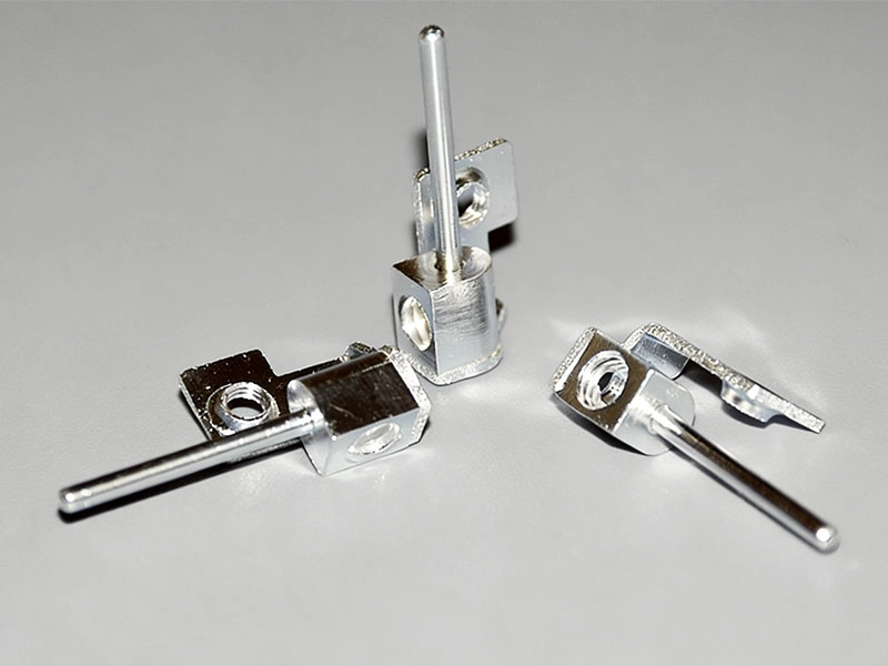
تُعدّ هذه الطريقة مثالية عندما يوفر الجزء المختوم بيانات تحديد مواقع قابلة للتكرار، وتكون دورة التصنيع الثانوية قصيرة. وتكون أقل جاذبية عندما يؤدي تشوه التشكيل إلى عدم استقرار التثبيت، أو عندما لا تزال معظم الميزات تتطلب عمليات تشغيل. كتلة طرفية مطبوعة على لوحة الدوائر المطبوعة مع تشغيل ثانوي يوضح هذا المبدأ: فمساره المنشور يجمع بين الختم الدقيق، والثني، والتثقيب، والحفر، والطلاء الكهربائي.


كتلة طرفية للوحة الدوائر المطبوعة مصنعة من خلال عمليات التشكيل الدقيق، والثني، والتثقيب، والحفر، والتشغيل الثانوي

لماذا لا تؤتي أدوات التشكيل بالختم ثمارها دائماً؟

مراعاة الطلب على مدار العمر والتغييرات والعمليات الخفية

قد لا يؤدي قصر دورة حياة المنتج، أو كثرة تعديلات العملاء، أو عدم استقرار الطلب، إلى استهلاك كميات كافية من الأجزاء لاسترداد تكلفة القالب. لذا، يُنصح بنمذجة الكميات المنخفضة والمتوقعة والعالية طوال دورة حياة المنتج بدلاً من الاعتماد على توقعات سنوية متفائلة واحدة.

يجب أن تشمل التكلفة النهائية للجزء المُختوم إزالة النتوءات، والتثقيب، والتشغيل الآلي، والتنظيف، والطلاء، والتغطية، والفحص، والتجميع، والتغليف، وصيانة الأدوات، وأي تعديلات محتملة. ينبغي أن يوضح عرض السعر ما إذا كانت التجارب، وفحص العينات، وجولات المراجعة، والشحذ، وقطع الغيار، والتخزين، والصيانة مشمولة. قد تؤدي التغييرات التي تطرأ بعد بدء تصنيع القالب إلى زيادة التكلفة والتأخير، مما يجعل إصدار الأدوات بشكل رسمي إجراءً رقابيًا أساسيًا.

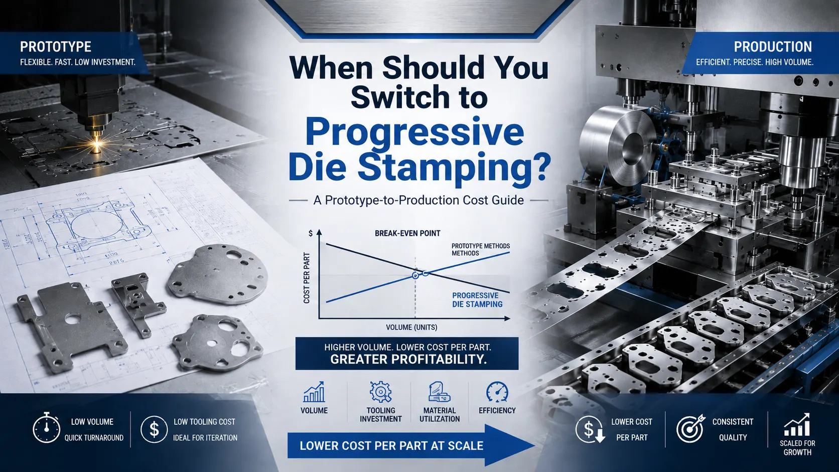
كيفية حساب نقطة التعادل لأدوات التشكيل بالضغط

قارن بين مسارين تصنيعيين محددين بالكامل:

كمية التعادل = استثمار الأدوات ÷ (تكلفة وحدة CNC المكتملة - تكلفة وحدة التشكيل المكتملة)

يُعدّ "الإنجاز" أمراً بالغ الأهمية. يجب أن تشمل تكلفة التصنيع باستخدام الحاسوب (CNC) المواد، والإعداد، والتشغيل الآلي، والأدوات، والفحص، والتشطيب، والتغليف. أما تكلفة التشكيل بالضغط (Skembing) فيجب أن تشمل تصميم القالب، والتجارب، وإنتاج المكابس، واستخدام المواد، والصيانة، والعمليات الثانوية، والفحص، والتشطيب، والتغليف.

إذا كانت قطعة خام مختومة لا تزال بحاجة إلى ثقوب وخيوط CNC، فاستخدم تكلفة القطعة الهجينة النهائية، وليس سعر عملية الكبس فقط. اختبر عدة سيناريوهات لكميات الإنتاج. يؤدي فرق بسيط في تكلفة الوحدة إلى فترة استرداد طويلة؛ بينما قد يبرر فرق أكبر الحاجة إلى الأدوات في وقت أقرب.

اطلب من كل مُقدّم عرض أسعار أن يُقدّم نفس تفاصيل مراجعة الرسم، والمواد، ونطاقات الكميات، ونطاق الفحص، والتشطيب، والتغليف، وشروط ملكية الأدوات. وإلا، فقد تُغطي عروض الأسعار أعمالاً مختلفة. الإجابة الصحيحة على سؤال "ما هو حجم الإنتاج الذي يُبرّر استخدام أدوات التشكيل بالضغط؟" هي نطاق نقطة التعادل الخاص بكل مشروع، وليس رقماً عاماً في هذا القطاع.

هل القطعة المصنعة باستخدام آلة CNC مناسبة لعملية ختم المعادن؟

حدد أولاً ما إذا كان بالإمكان إنتاج الشكل الهندسي من صفائح أو لفائف. تقوم عملية التشكيل بالختم بقطع وتشكيل المواد المسطحة، بينما تزيل عملية التشغيل الآلي المادة من قطعة العمل الصلبة. قد لا يمكن تحويل المقاطع السميكة أو الأشكال المغلقة أو الأشكال الهندسية المعقدة متعددة المستويات بشكل مباشر.

فصل الميزات القابلة للختم عن الميزات المصنعة آليًا الهامة

ابدأ بالشكل الأساسي. هل يمكن استخدام سماكة ثابتة للصفائح في هذه الوظيفة؟ راجع الانحناءات، وعمق السحب، وعلاقات الثقوب بالحواف، والارتداد، والأسطح الحساسة للنتوءات.

صنّف خصائص الرسم إلى ثلاث مجموعات: مناسبة للختم، قابلة للتنفيذ بعد تغيير التصميم أو التفاوتات، وما زالت تتطلب تشغيلًا آليًا. قد تبقى الثقوب الدقيقة، والخيوط العميقة، وأسطح منع التسرب، ومواقع المحامل، وأسطح الإسناد عمليات ثانوية. تأكد من تحديد نقاط الإسناد، وبدل التشغيل الآلي، وكيف سيؤثر اختلاف التشكيل على الإعداد النهائي. يُستخدم التشغيل الآلي الثانوي باستخدام الحاسوب (CNC) عادةً للثقوب عالية الدقة وأسطح التثبيت على المكونات المختومة.

كيفية الانتقال من النموذج الأولي المُصنّع باستخدام الحاسوب إلى الإنتاج بالختم

يُثبت النموذج الأولي المُصنّع باستخدام الحاسوب (CNC) الوظيفة، ولكنه لا يُثبت بالضرورة إمكانية التشكيل بالضغط. قد يحتوي رسمه على زوايا حادة، أو سماكة متغيرة، أو تفاوتات دقيقة ناتجة عن عمليات التصنيع الآلي وليس التشكيل.

تجميد المتطلبات، ثم استخدام DFM والموافقة على المادة الأولى

قبل البدء في تصنيع الأدوات الصلبة، يجب التأكد من المواد، والسماكة، والوصلات، والأبعاد الحرجة، والتشطيب، ومراجعة الرسم. ينبغي أن تظل المشاريع التي لا تزال تخضع لتغييرات وظيفية أو تغييرات تتعلق بواجهة العميل في مرحلة مرنة حتى يتم حل المخاطر الرئيسية.

يتبع الانتقال المُتحكم فيه التسلسل التالي: التحقق من صحة النموذج الأولي، تصميم المنتج للتصنيع، مراجعة رسم الإنتاج، تصميم الأداة، تجربة الأداة، فحص العينة، التصحيح، الموافقة على النموذج الأولي، التشغيل التجريبي، وإصدار الإنتاج. يجب أن يشمل فحص العينة النتوءات، والشقوق، والتجاعيد، والارتداد، وحالة الطلاء، والمظهر، وأداء التجميع، وليس الأبعاد فقط.

ما الذي يجب على المشترين تضمينه في طلب عرض أسعار من CNC إلى التشكيل بالضغط

يتطلب الحصول على عرض أسعار دقيق الرسم ثنائي الأبعاد الحالي وملف STEP، وشكل المادة والمخزون، والسمك، والكميات السنوية والكميات طوال العمر، والعملية الحالية، والتفاوتات الحرجة، والتشطيب، والتشغيل الثانوي، والفحص، والتعبئة والتغليف، والتغييرات المعروفة.

قارن أيضًا بين ملكية الأدوات، وتخزينها، وصيانتها، وشحذها، وقطع الغيار، ورسوم التعديل، وحقوق النقل، وإجراءات إنهاء البرنامج. قد يؤدي انخفاض سعر القالب إلى تكاليف لاحقة إذا لم تُؤخذ في الاعتبار التغييرات الهندسية أو دعم الإنتاج.

اختيار مورد لعملية الانتقال من التصنيع باستخدام الحاسوب (CNC) إلى التشكيل بالضغط

ينبغي على المورد المؤهل تقييم كلا المسارين. والتحقق مما إذا كانت الأدوات تُصنع داخلياً، وما إذا كانت فرق التجربة والإنتاج تتشارك المسؤولية، وما إذا كان من الممكن تنسيق الأعمال الثانوية، وكيف يتم التحكم في النماذج الأولية والتعديلات وتآكل الأدوات والإجراءات التصحيحية.

تجمع شركة تشجيانغ تشوانغكاي للتكنولوجيا الميكانيكية والكهربائية المحدودة، والمعروفة أيضًا باسم سي كي ميتال تك، بين الأدوات، وختم المعادن، والتشغيل الآلي باستخدام الحاسوب، ومعالجة الأسطح، والفحص، والتجميع ضمن نطاقها تصنيع المعادن الدقيقة المتكاملة نطاق أعمالها. تشمل مواردها المؤكدة 8 ماكينات CNC رباعية المحاور، و18 مخرطة CNC دقيقة، وقدرات تصنيع من النوع السويسري. كما تنتج شركة CK Metal Tech أدوات التشكيل التدريجي، وأدوات السحب، والأدوات المركبة، وهي حاصلة على شهادة IATF 16949. وهذا يدعم عمليات التصنيع الكاملة باستخدام CNC، وعمليات التشكيل الكاملة، ومراجعات المسارات الهجينة.

خاتمة

تُصبح أدوات التشكيل بالضغط مُجدية عندما يكون الجزء قابلاً للتشكيل بالضغط فعلاً، ويكون التصميم مستقراً، وتتجاوز وفورات العمر الافتراضي تكاليف الأدوات والصيانة والتحقق والمعالجة الثانوية ومخاطر التعديل. ولا تزال عمليات التصنيع باستخدام الحاسوب (CNC) مفيدة للنماذج الأولية، وتغيير التصاميم، والهياكل الصلبة، والميزات الدقيقة. وقد تكون العملية الهجينة هي الخيار الأمثل عندما يكون الشكل الأساسي قابلاً للتشكيل بالضغط، ولكن لا تزال الواجهات الوظيفية تتطلب التصنيع الآلي.

لإجراء مراجعة للمشروع، يُرجى إعداد أحدث الرسومات، وملف STEP، والمواد، والكمية المستهدفة، ومدة البرنامج، والأبعاد الحرجة، والعمليات الثانوية، ومتطلبات الجودة. تُمكّن هذه التفاصيل شركة CK Metal Tech من اطلب مراجعة DFM من CNC إلى التشكيل بالضغط ومقارنة المسارات الممكنة دون الحاجة إلى التزام فوري بتوفير الأدوات.

الأسئلة الشائعة

ما هو حجم الإنتاج الذي يجعل عملية ختم المعادن أرخص من عملية التصنيع باستخدام الحاسوب (CNC)؟

لا توجد كمية عالمية. احسب نقطة التعادل من خلال الاستثمار الفعلي في الأدوات والفرق بين تكاليف وحدة CNC ووحدة التشكيل بالختم المكتملة، بما في ذلك الصيانة والأعمال الثانوية والتشطيب والفحص ومخاطر تغيير التصميم.

هل يمكن تحويل قطعة مصنعة باستخدام آلة CNC مباشرة إلى قطعة معدنية مختومة؟

أحيانًا، ولكن عادةً ليس بدون تصميم قابل للتصنيع. قد تتطلب المقاطع الصلبة، أو السماكة المتغيرة، أو الميزات العميقة، أو التفاوتات الدقيقة إعادة تصميم قبل بدء عملية التصنيع.

هل لا تزال الأجزاء المختومة بحاجة إلى التصنيع باستخدام الحاسوب (CNC)؟

قد يكون ذلك ممكناً. يمكن أن تتطلب الخيوط، والثقوب الدقيقة، وتركيبات المحامل، وأسطح منع التسرب، وأسطح المرجع، أو ميزات التثبيت الضيقة عمليات تشغيل ثانوية، أو حفر، أو تثبيت، أو توسيع، أو طحن.

كيف يمكن للمشتري أن يعرف ما إذا كانت أدوات التشكيل بالضغط ستؤتي ثمارها؟

تأكد من إمكانية تصنيع المنتج، ثم قارن تكاليف دورة الحياة الكاملة في ظل سيناريوهات الطلب المنخفض والمتوقع والعالي. وتكون الحجة أقوى عندما يكون التصميم نهائيًا وتُدرج العمليات المخفية في كلا العرضين.

ما الذي يجب التحقق منه عند اختيار شركة مصنعة لأدوات التشكيل بالضغط؟

التحقق من تصميم الأدوات الداخلية، ودعم التصميم للتصنيع، والتجارب، وإجراءات النموذج الأولي، والتحكم في المراجعة، والتشغيل الثانوي، والتفتيش، وصيانة الأدوات، وشروط الملكية، وإدارة جودة الإنتاج.

30th يوليو 2026
بيت
واتساب
بريد إلكتروني
جهات الاتصال