


CHUANGKAI

un je l un n d

Chargement

     
maison // blog

Blog de l'industrie

Tooling DFM for Metal Stamping: Prevent Die Rework


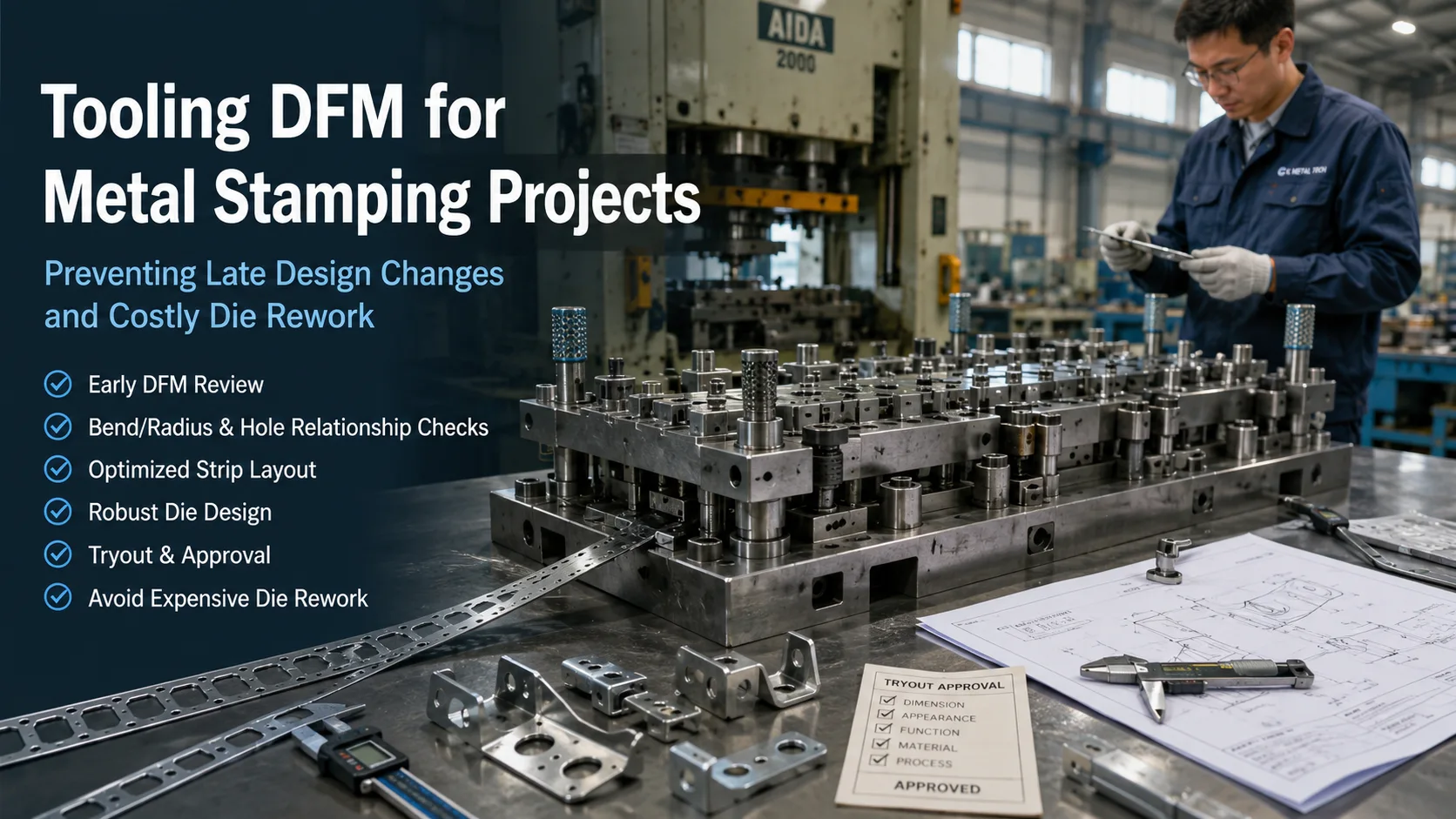
Tooling DFM for Metal Stamping Projects Preventing Late Design Changes and Costly Die Rework

Tooling DFM (design for manufacturing) connects a stamped-part drawing to a workable die, press route, material, and inspection plan before steel is cut. Its value is highest before tool release, when a change to a bend, hole, radius, or strip layout is still a drawing edit rather than die rework. The goal is to freeze the right requirements early and expose risks while they remain inexpensive to correct.

A disciplined review asks: Can the geometry be formed from the selected stock? Can the die support tolerance and tool-life needs? Can the finished part be inspected and assembled? What happens if the design changes after tooling starts? These answers create a gate between prototype approval and production tooling.

What Tooling DFM Should Confirm Before Die Design

Start with function, stock form, and production intent

Begin with the part’s job, not just its current CAD shape. Identify load paths, contact surfaces, spring features, sealing edges, electrical interfaces, and cosmetic faces. Then confirm material grade, temper, thickness, coil or blank form, grain direction where relevant, and expected annual and lifetime quantities. A part designed around CNC machining may contain solid sections, sharp internal corners, or tolerances that are unsuitable for sheet-metal forming.

The DFM review should also state whether the route is progressive die stamping, compound die stamping, drawing, bending, or a hybrid with secondary machining. Buyers evaluating precision stamping tooling design and manufacturing should expect the supplier to explain why the proposed route fits the geometry and demand rather than simply quote a die price.

Freeze interfaces before optimizing minor features

Late changes are most disruptive when they affect mounting holes, connector locations, datums, bend directions, mating edges, or the finished envelope. Mark these as controlled interfaces; review cosmetic improvements and non-critical reliefs separately. This prevents a low-risk change from reopening the entire die.

Geometry Checks That Prevent Die Rework

Review bend radii, hole relationships, and edge distances

Inside bend radius, material thickness, hole-to-edge distance, slot orientation, and flange length determine whether a feature can be formed without cracking, distortion, or an unstable die condition. Small holes close to a bend may deform during forming. Narrow webs can tear or buckle. Sharp corners often require a radius, relief, or a different operation sequence.

The drawing should identify the formed condition, not only the flat pattern. Show bend direction, critical radii, profile tolerances, and any areas where burr direction matters. If a feature is possible only after a design adjustment, document the adjustment and obtain approval before tool detailing.

Account for springback and forming variation

Springback depends on material, thickness, grain direction, bend geometry, tooling, and process controls. A nominal CAD angle is not proof of the released angle. The supplier should identify compensation, restrike, coining, or measurement steps where the assembly requires a stable formed position. Do not hide a springback problem with a broad tolerance that later causes poor fit.

Decide which features stay secondary

Not every hole, thread, bore, or datum must be forced into the stamping die. Tapping, reaming, machining, or a light calibration operation may be safer for a critical interface. Classify features as stamped, stamped with a tolerance change, or completed in a secondary process. This prevents an expensive die revision when a short downstream operation would protect function.
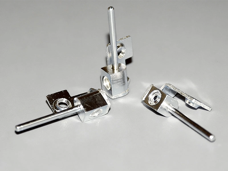
 

Precision-stamped PCB terminal block with bending, tapping and drilling

Strip Layout and Die Architecture

Strip layout affects material use, carrier strength, orientation, burr direction, and station count. Progressive dies suit repeat features across a coil; compound dies combine blanking and piercing; drawing dies form depth but require control of flow, wrinkles, thinning, and draw beads. Review the concept against geometry, press capability, feed direction, and a suitable simulation or trial plan.

Materials, Tolerances, and Secondary Operations

Material selection influences tool wear, burrs, springback, cracking, conductivity, corrosion, and cost. Confirm the approved grade and alternatives before tool steel and clearances are finalized; a substitution may form differently or change tonnage.

Separate general tolerances from functional tolerances. Tightening every dimension can increase stations, tool complexity, inspection effort, and rework without improving assembly. Define critical hole positions, flatness, bend angles, contact faces, and profile features, then specify how they will be measured after forming and any secondary work.

Finishing also belongs in DFM. Deburring, tumbling, plating, powder coating, painting, cleaning, and assembly can change dimensions or mask defects. Identify coated or plated surfaces, no-finish zones, thread protection, and cosmetic standards before the first trial. Buyers seeking services d'emboutissage et d'outillage de métaux sur mesure should ask how the die design accounts for these downstream operations.

Change-Control Gates That Protect the Tool Investment

Use formal gates instead of informal email approvals. A workable sequence is:

  • Design input freeze: function, material, thickness, interfaces, quantity, and finish are documented.
  • DFM sign-off: geometry, strip layout, die concept, tolerances, and secondary operations are reviewed.
  • Tool release: the controlled drawing and revision are approved for detailed design and procurement.
  • Tryout review: samples are checked for dimensions, burrs, cracks, wrinkles, springback, and assembly fit.
  • First-article approval: corrections are closed, records are issued, and later changes follow a defined process.

If a change arrives after tool release, classify it before authorizing work. A note may need no steel change; a moved hole may need an insert; a new bend or thickness may require station redesign. Record affected components, samples, schedule impact, and approval owner so an urgent request becomes a controlled decision.

What to Include in a Tooling DFM RFQ

Send the latest 2D drawing, 3D model, revision history, material and thickness, flat pattern, annual and lifetime quantities, press constraints, critical tolerances, burr direction, finish, secondary operations, inspection requirements, and open design issues. State whether the part is a prototype, released design, or CNC conversion.

Ask each supplier for a marked-up drawing or DFM report showing proposed radii, hole changes, forming sequence, strip concept, datums, and unresolved risks. Clarify tool ownership, maintenance, sharpening, spares, modification charges, trial samples, and engineering-change pricing so metal stamping services quotes cover comparable scope.

Working With an Integrated Stamping and Tooling Supplier

CK Metal Tech describes precision tooling design and manufacture alongside high-speed stamping, CNC machining, sheet metal fabrication, finishing, inspection, and assembly. Its published tooling scope includes progressive, drawing, and compound die approaches, with stamping materials such as brass, copper alloys, steel, stainless steel, and cold-rolled strip.

The supplier also presents a progressive die stamping terminal strip as a repeatable formed-component example. Capabilities alone do not prove a specific die’s tolerance or life; CK Metal Tech should confirm the drawing, material, quantity, press window, inspection plan, and change-control rules.

For broader supplier-selection context, see the custom metal stamping and tooling supplier guide, then use the DFM report and approved revision as the working baseline for the new project.

Conclusion

Tooling DFM prevents die rework by exposing forming limits, material behavior, tolerance conflicts, strip-layout tradeoffs, and finishing risks before release. The process separates controlled interfaces from flexible features, documents secondary operations, and uses approval gates through first article.

Prepare the drawing revision, material, thickness, quantity, critical interfaces, finish, inspection needs, and known changes before requesting a review. OEM teams can contact CK Metal Tech for a stamping DFM review and ask for a route recommendation, marked-up risks, trial plan, and change-control scope.

FAQ

When should tooling DFM start on a metal stamping project?

Start after the functional concept is clear but before detailed die design or steel procurement. The review should precede production-tool release and include material, interfaces, quantities, tolerances, and finishing.

Which design changes are most likely to require die rework?

Moved holes, changed bend directions, new flanges, altered material thickness, revised draw depth, and changes to critical datums can affect stations or die components. The actual impact depends on the tool architecture.

Can a stamped part use secondary machining?

Yes. Tapping, reaming, milling, or calibration may be appropriate for precision bores, threads, datum faces, or other features that are risky to hold directly in forming. Classify these operations during DFM.

What should a supplier include in a tooling DFM report?

Request a marked-up drawing, forming and strip-layout assumptions, proposed die route, material risks, tolerance comments, secondary operations, trial plan, inspection points, and a list of open decisions requiring customer approval.

25th septembre 2026
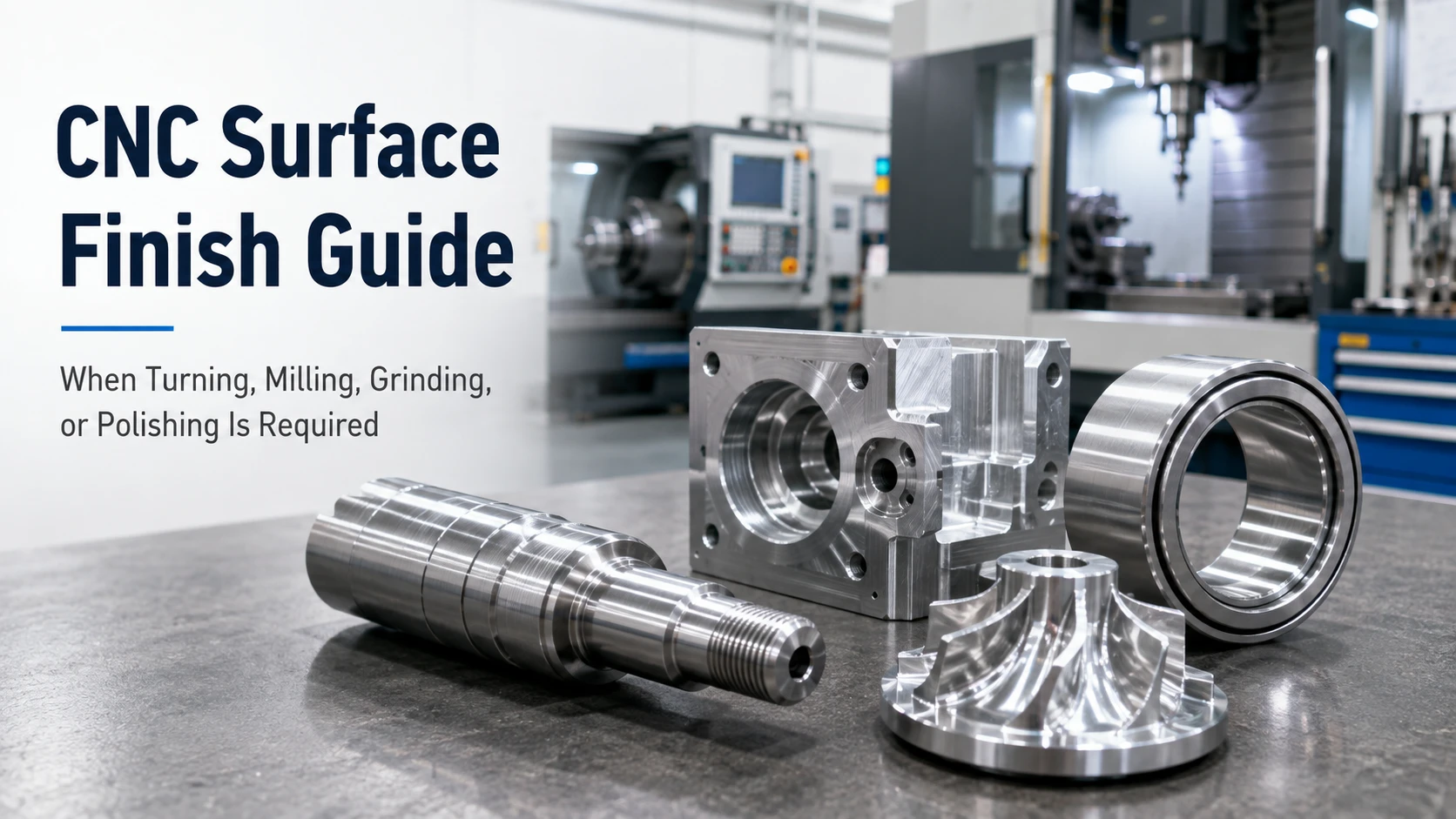
CNC Surface Finish: When to Turn, Mill, Grind or Polish


CNC Surface Finish Guide When Turning, Milling, Grinding, or Polishing Is Required

Choosing a CNC surface finish should start with what the part must do, not with a favorite machine or a shiny appearance. CNC turning or milling may meet the drawing on many parts. Grinding becomes useful when a surface must hold tighter geometry after heat treatment or support a bearing, seal, or sliding fit. Polishing is justified when friction, cleanability, reflectivity, or cosmetic uniformity matters after the geometry is already under control.

For OEM buyers, the practical decision is to connect the required surface condition to the manufacturing sequence. A clear drawing identifies functional faces, roughness parameters, edge treatment, and inspection method so a supplier can select turning machining, CNC milling machining, grinding machining, or polishing without adding unnecessary operations.

Read the Drawing Before Choosing a Finish

Surface roughness is a functional requirement

Ra and Rz describe aspects of a measured profile, while lay describes tool-mark direction. Roughness alone does not define flatness, roundness, waviness, burrs, or visual uniformity. A shaft can meet an Ra target yet fail a seal because of a damaged edge or poor cylindricity.

The drawing should identify the datum system, critical dimensions, roughness symbols, surface lay where relevant, edge breaks, and areas that may not be touched by a later process. If the specification uses machining finish symbols, pair them with a measurable requirement and a defined inspection location. Avoid writing only “smooth finish” or “polished” because different suppliers may interpret those words differently.

Separate critical and non-critical surfaces

Mark bearing seats, seal grooves, sliding faces, threads, electrical contacts, cosmetic panels, and hidden surfaces. Leave non-critical faces at the normal CNC condition and reserve extra work for functional areas to control cost and dimensions.

When CNC Turning Is Enough

CNC turning is usually the first process for shafts, pins, sleeves, bushings, collars, and other rotational parts. It can provide a consistent texture when diameter, concentricity, shoulders, threads, and edges meet the drawing. Adding grinding or polishing only for appearance can remove stock and increase handling.


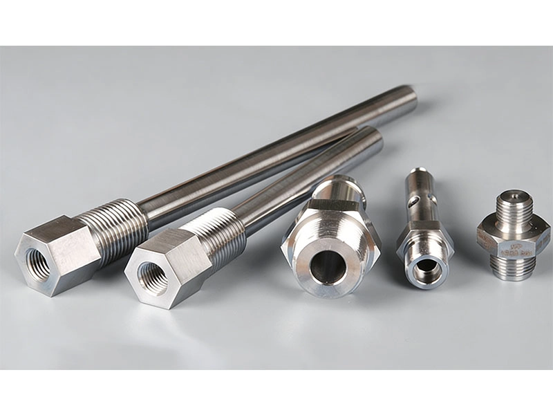
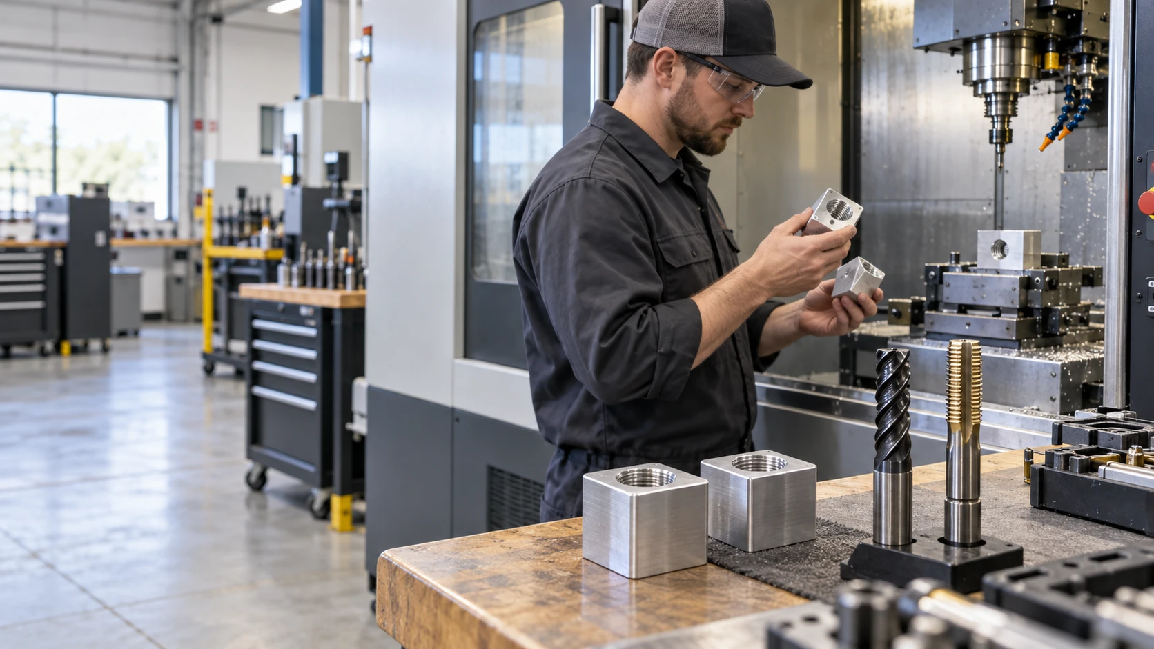
CNC turned 304316L stainless steel hydraulic fitting with threaded machined surface

Turning is often sufficient when the surface is not a hardened bearing fit, demanding seal, or fine cosmetic face. Tool nose radius, insert condition, feed, speed, workholding, and material influence the profile. The supplier should confirm achievable roughness and the deburring pass.

Inspect turned surfaces where they control assembly: diameter, roundness or concentricity, thread engagement, shoulder squareness, burrs, and lay. A profilometer reading cannot replace dimensional checks.

When CNC Milling Is Enough

CNC milling is the normal starting point for plates, brackets, pockets, housings, slots, and contoured faces. A suitable cutter, stable workholding, and a finishing pass can produce a reliable surface without secondary work. Results depend on cutter, step-over, toolpath, material, and whether the face is visible or functional.

Milling may be enough for mounting faces, pockets, and general components when normal tool marks are acceptable. For visible faces, specify acceptable marks and transitions. For mating faces, define flatness, parallelism, and hole position in addition to roughness.

Buyers comparing custom CNC machining services should ask for a sample or first-article review that shows the actual toolpath and fixture condition. A finish achieved on a small coupon may not represent a large plate, a deep pocket, or a thin wall that can vibrate during cutting.

When Grinding Is Required

Grinding is controlled abrasive stock removal for surfaces that need tighter size, geometry, or roughness than turning or milling can hold. It is commonly considered for hardened shafts, bearing journals, precision bores, guide surfaces, sealing diameters, and flat faces. Internal, external cylindrical, centerless, and surface grinding suit different geometries.

Plan grinding in the drawing and process route. Leave stock, define the post-heat-treatment datum, and protect edges from burns or breakage. A route may be rough turning or milling, heat treatment, finish grinding, cleaning, and inspection. Hardness, length, wall thickness, and clamping affect the result.

A grinding callout does not solve distortion automatically. Measure runout, cylindricity, taper, flatness, and size at functional locations, and review protection and datum relationships for threads, keyways, and cross-holes.

When Polishing Is Required

Polishing is appropriate when an application needs lower friction, easier cleaning, controlled reflectivity, or a uniform visible appearance after machining. It is often used on stainless steel, exposed hardware, fluid-contact areas, and surfaces where tool marks must be blended. The method should match material and geometry.

Polishing cannot correct diameter, flatness, or hole location. It can round edges, smear soft material, or change a weld transition. Define polished surfaces, finish direction or uniformity, protected zones, and the inspection sample. If coating or plating follows, confirm whether polishing is preparation or the final finish.

Combine Processes in a Controlled Sequence

Many precision parts need a hybrid route rather than one preferred finish. A practical sequence may be:

  • Turn or mill the near-net geometry and leave controlled stock on critical faces.
  • Complete heat treatment or another dimensional-changing operation.
  • Grind the bearing, sealing, or locating surfaces to the final geometry.
  • Polish only the specified cosmetic, low-friction, or cleanable areas.
  • Clean, protect, and inspect the part before assembly or packaging.

The sequence should be frozen during design for manufacturing review. Changing from milling to grinding late can affect stock allowance, datums, edge breaks, inspection equipment, and cost. Changing from polishing to a coating can also alter dimensions and masking requirements.

What to Include in a CNC Surface-Finish RFQ

Provide the current 2D drawing, 3D model, revision, material and hardness condition, critical datums, roughness parameters, surface lay, edge and burr requirements, cosmetic zones, heat-treatment state, quantity, and inspection method. State whether the part is a shaft, bushing, machined plate, housing, seal component, or another assembly element.

Ask the supplier to identify the proposed primary and secondary processes, stock left for grinding, polishing limits, workholding risks, cleaning method, and first-article evidence. For buyers sourcing precision machining services, this discussion is more useful than requesting a generic “mirror” or “high-quality” finish.

Working With an Integrated CNC Machining Supplier

CK Metal Tech presents a precision machining route covering CNC turning, milling, drilling, tapping, grinding, thread rolling, polishing, and related equipment. Its precision machining service lists cylindrical and centerless grinders, polishing machines, and cleaning equipment. The company also presents CNC machining services for precision metal parts for drawing-based production.

This range can keep primary cutting, secondary finishing, cleaning, and inspection connected. It does not make every material, tolerance, hardness, or finish automatic. CK Metal Tech should confirm the drawing, envelope, critical surfaces, stock allowance, measurement method, and lot pattern before selecting a route.

When machined parts connect to formed housings or brackets, the precision sheet metal manufacturing service can help align mating surfaces and finishing requirements across the assembly.

For broader process context, buyers can review precision CNC machining for OEM metal parts, then request a drawing-based review rather than assuming the same finish applies to every component.

Conclusion

Turning and milling are often sufficient for general surfaces when the drawing accepts their normal texture and the geometry is stable. Grinding earns its place when size, roundness, flatness, or post-heat-treatment condition requires controlled stock removal. Polishing is a selective final operation for friction, cleaning, reflectivity, or appearance, not a replacement for dimensional control.

Define function, datums, roughness, lay, edges, sequence, and inspection points before asking for a quote. OEM teams can contact CK Metal Tech for a CNC finish review with the drawing, material, hardness, critical surfaces, quantity, and application conditions.

FAQ

Is a milled or turned finish good enough for every CNC part?

No. It may be suitable for general faces, but seals, bearings, sliding interfaces, hardened surfaces, or cosmetic areas may require grinding or polishing. The drawing and application should decide.

What is the difference between grinding and polishing?

Grinding primarily controls size, geometry, and roughness through controlled abrasive stock removal. Polishing is usually a later operation focused on friction, cleanability, reflectivity, or visual uniformity after the geometry is established.

Should polishing be specified with a target Ra?

When roughness is functionally important, a measurable Ra or Rz requirement is useful. Also define the area, lay, edge condition, and inspection method because a single number does not describe visual uniformity or geometry.

How can an OEM avoid unnecessary surface-finish cost?

Separate critical from non-critical surfaces, specify normal CNC finish where acceptable, reserve grinding or polishing for marked areas, and agree on the process sequence and first-article inspection before production.

24th septembre 2026

Medical Equipment Enclosures: Powder Coating & Cleanability


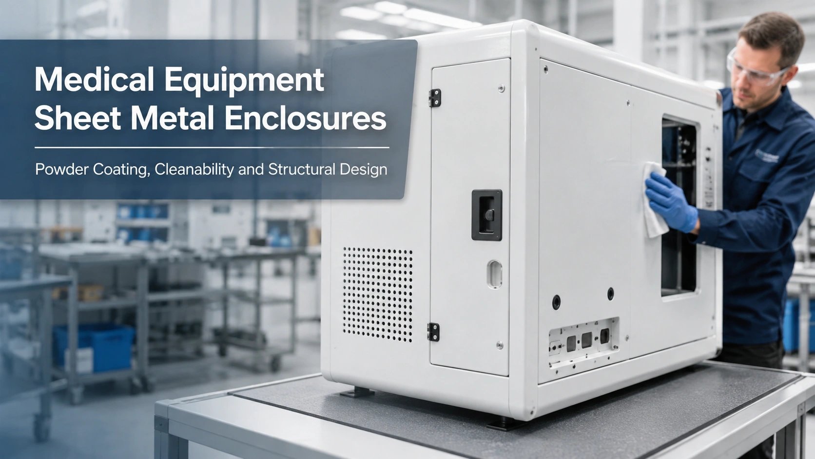
Medical Equipment Sheet Metal Enclosures Powder Coating, Cleanability and Structural Design

Medical equipment sheet metal enclosures have to do more than cover electronics. They must support cleaning routines, protect internal components, hold panels and interfaces in alignment, and remain practical to fabricate and service. Powder coating can provide a durable, attractive surface, but it is not a substitute for a validated cleaning protocol, material compatibility review, or medical-device quality plan.

Good design connects cleaning access, structural loads, and repeatable fabrication from the start. Treating them as one problem reduces late changes between engineering, manufacturing, and quality teams.

Start With the Enclosure’s Cleaning and Use Environment

Separate patient-contact risk from equipment-housing needs

Diagnostic cabinets, imaging covers, rehabilitation shells, laboratory panels, and support structures often sit outside the patient-contact path. Their requirements differ from parts touching tissue, fluids, or sterile fields. The device team should define risk classification, cleaning agents, wipe frequency, and disinfectant exposure; “medical” alone is not a specification. For a non-patient-contact housing, focus on an intact wipeable surface, chemical resistance, and protected seams. Sterile or controlled workflows may need additional validation, which remains the device manufacturer’s responsibility.

Map where soil and fluid can collect

Geometry drives cleanability. Deep pockets, narrow ledges, exposed fastener recesses, rough weld transitions, open seams, and sharp corners can retain residue. Mark high-touch areas, wipe paths, openings, removable panels, hinges, handles, and cable interfaces before release. Rounded transitions help, but the key is showing how a technician reaches required surfaces and how residue exits instead of migrating into sensitive areas.

How Powder Coating Supports Cleanable Medical Housings

Powder coating is a dry finishing process in which charged powder is deposited on a grounded metal part and then cured. On suitable sheet metal, a well-prepared and intact coating can create a continuous protective surface that is easier to wipe than bare steel with exposed grinding marks or oxidation. The finish can also protect edges and broad panels during handling, shipping, and routine service.


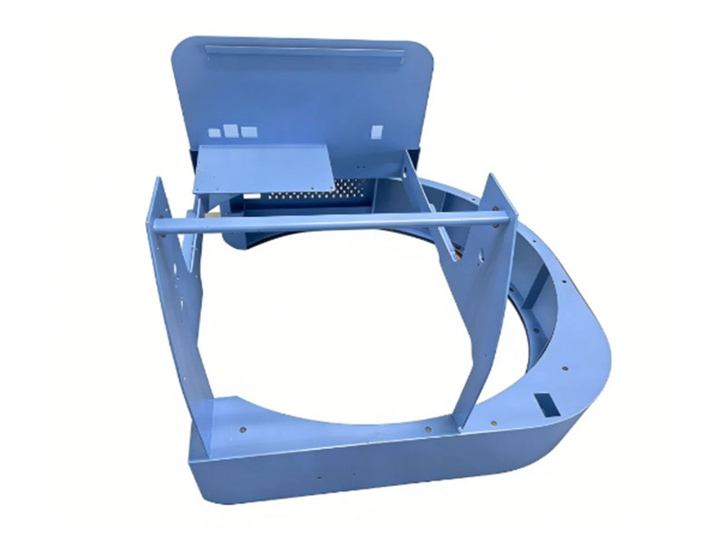
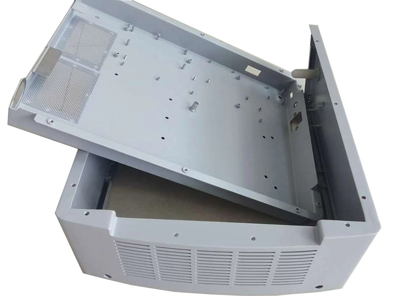
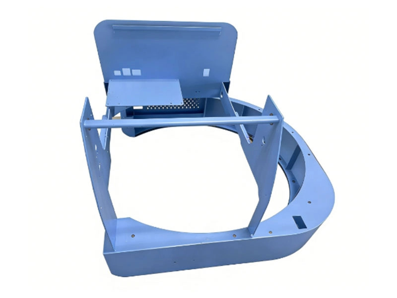
Curved medical equipment sheet metal enclosure with powder-coated SPCC housing

Specify the surface instead of writing only “medical coating”

An RFQ should state color reference, gloss or texture, visible surfaces, coating thickness if controlled, masked areas, approved cleaning chemicals, wipe frequency, and appearance limits. “Medical-grade” is not a complete requirement; powder chemistry, substrate preparation, cure schedule, and finished-part validation must match the application.

Do not infer antibacterial or disinfectant performance from a generic powder specification. CK Metal Tech’s Boîtier en tôle incurvée pour équipement médical is described with an antibacterial, easy-to-clean surface, but the test method, chemical list, exposure time, and acceptance criteria must be confirmed for each device program.

Protect functional contact areas from coating buildup

Threads, grounding points, hinge pins, sliding faces, gasket lands, connector panels, and tight interfaces may need masking. Identify them on the drawing and balance fit against exposed substrate. Check the approved sample after coating for panel fit, fastener engagement, grounding continuity, connector alignment, ventilation openings, and visible-face appearance. See powder coating for sheet metal enclosures for broader masking context.

Structural Design Priorities for Medical Equipment Enclosures

Choose material and thickness around loads, not appearance

Cold-rolled steel, stainless steel, and aluminum are common options. Select among them for stiffness, weight, corrosion exposure, forming, grounding, and finish, not appearance alone. Define unsupported spans, mounting method, fasteners, impact or vibration, and internal-module alignment. Local reinforcement for a display, fan, or pump may matter more than nominal wall thickness.

Control weld distortion and panel alignment

Welded housings combine panels, formed corners, brackets, doors, and frames. Heat input and weld sequence can shift flange flatness, gaps, holes, or cosmetic faces; excessive grinding can thin edges or show through powder. Use functional datums for doors, hinges, cutouts, connectors, openings, and feet, and define post-weld inspection points. A DFM review before fixture release is easier than correcting misalignment after coating.

Keep access, ventilation, and serviceability visible in the design

Ventilation slots, interface panels, removable covers, and cable routes must meet thermal and electrical needs without inaccessible ledges or sharp wipe traps. Specify hinge, latch, handle, edge, and coating details together when access is frequent. Check burr removal, edge protection, and whether technicians can clean around openings without pushing debris inside.

A Practical Design-to-Production Review

Before prototype approval, ask the supplier to review five connected areas:

  • Cleaning path: Which surfaces are wiped, with which agents, and how are ledges, seams, and openings reached?
  • Structural path: Where do loads enter the shell, and which panels or brackets need reinforcement?
  • Process path: Can cutting, bending, welding, grinding, masking, coating, and inspection be repeated with the current drawing revision?
  • Assembly path: Do coated holes, threads, grounding zones, seals, hinges, and interfaces fit after finishing?
  • Evidence path: Which first-article measurements, finish checks, cleaning tests, or device-level validations will be recorded?

This review should include a marked-up drawing, not only a 3D render. Mark cosmetic faces, no-coat zones, datums, weld symbols, surface transitions, lifting points, and inspection locations. If cleaning chemistry or validation is still under development, label it as an open input so the supplier does not quietly choose an assumption.

Working With an Integrated Sheet Metal and Finishing Supplier

Cleanable enclosures are easier to manage when one supplier discusses fabrication and finishing together. CK Metal Tech lists laser cutting, CNC punching, bending, riveting, welding, and grinding for stainless steel, carbon steel, silicon steel, aluminum alloy, galvanized sheet, and aluminum-zinc plated sheet in its precision sheet metal manufacturing service. Its powder coating and painting capability includes an automatic line, manual coating for large parts, and manual painting.

Those capabilities are relevant to a medical enclosure route that combines formed panels, welded structures, cosmetic grinding, and a finished surface. They do not, by themselves, establish biocompatibility, sterilization resistance, antibacterial efficacy, or device regulatory compliance. The engineering team should confirm the actual substrate, dimensions, cleaning chemicals, coating system, masking, inspection, and validation requirements for each program.

What to Include in the Medical Enclosure RFQ

Send the current 2D drawing and 3D model, revision level, material and thickness, overall envelope, unsupported spans, mounting and lifting points, doors or removable panels, ventilation and cable openings, color and texture, cosmetic surfaces, masking zones, cleaning agents, expected exposure, quantity, and packaging requirements. For OEM buyers comparing sheet metal fabrication, sheet metal finishing, and related medical device machining, this shared information keeps quotes comparable.

Also state whether the enclosure is patient-contact, near-patient, laboratory, imaging, diagnostic, rehabilitation, or general equipment housing. Include the required structural checks, dimensional inspection points, coating acceptance criteria, and any device-level cleaning or environmental validation. A clear RFQ lets the supplier identify what is confirmed, what is conditional, and what still needs a test plan.

Conclusion

Medical equipment sheet metal enclosures need coordinated decisions about cleanability, powder coating, structure, access, and manufacturing. A durable powder-coated surface can support wiping and protect fabricated panels, but only when the substrate, pretreatment, cure, masking, cleaning chemistry, and validation requirements are defined together. Structural reliability likewise depends on loads, datums, weld control, reinforcement, and service access rather than appearance alone.

For an engineering review, prepare the drawing revision, material, thickness, enclosure size, cleaning agents, finish, masked interfaces, structural loads, target quantities, and validation needs. You can contact CK Metal Tech for a medical enclosure fit review and ask the team to evaluate the proposed fabrication, coating, inspection, and assembly route.

FAQ

Is powder coating automatically suitable for medical equipment enclosures?

No. Suitability depends on the enclosure’s use environment, cleaning chemistry, substrate, coating system, cure, masking, and device-level validation. Patient-contact or sterile applications may require additional evidence.

Does an easy-to-clean coating make an enclosure compliant?

No. Cleanability is one design input. The device manufacturer must define intended use, cleaning and disinfection requirements, risk controls, and any applicable validation or regulatory documentation.

Which materials are common for medical equipment housings?

Cold-rolled steel, stainless steel, and aluminum can all be considered. Select among them using stiffness, weight, corrosion exposure, forming, grounding, finish, and assembly requirements.

What should be masked before powder coating?

Review threads, grounding points, hinge and sliding faces, gasket lands, connector interfaces, tight holes, and other assembly-critical surfaces. Confirm the no-coat plan on the drawing before first-article production.

18th septembre 2026

Automated Powder Coating Lines for OEM Sheet Metal


Automated Powder Coating Line for OEM Sheet Metal Parts When Continuous Flow Improves Efficiency and Consistency

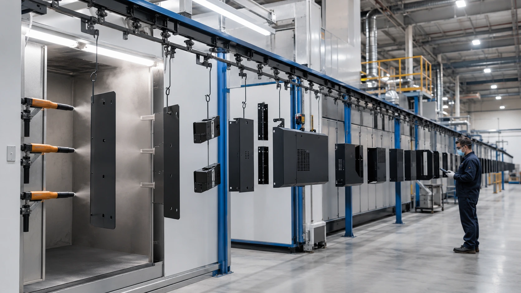
An automated powder coating line can improve efficiency and consistency when an OEM program has repeat demand, reasonably stable part families, controlled finish specifications, and enough work to keep the line balanced. It is not automatically the better route for every order. Large enclosures, frequent color changes, complex masking, highly variable geometries, or small mixed batches may still fit manual or batch coating better.

The useful sourcing question is, “Can the supplier standardize hanging, movement, spraying, curing, inspection, and unloading without creating a new bottleneck?” That distinction is more useful than a generic equipment list.

What Continuous Flow Changes in a Powder Coating Workflow

In a continuous system, parts move through defined process stages at a controlled pace instead of waiting for each batch to be completed and transferred. The exact configuration varies, but the workflow may connect cleaning or pretreatment, drying, powder application, curing, cooling, and unloading. The Powder Coating Institute explains the underlying electrostatic spray deposition and curing process: charged powder is attracted to a grounded part and then cured with heat to form the coating.

The line itself does not guarantee a good finish. Surface preparation, grounding, rack design, spray access, powder selection, cure conditions, masking, and inspection still control the result. Automation creates value when these inputs can be converted into repeatable operating windows.

When an Automated Powder Coating Line Improves Efficiency

Repeat demand supports stable loading and scheduling

Continuous flow is strongest when parts return in predictable quantities and can use repeatable racks, orientations, and color programs. Stable loading reduces setup decisions between pieces and makes line scheduling easier. Similar panels, covers, brackets, and enclosure components can often be grouped into part families, provided their weight, geometry, hanging points, and finish requirements are compatible.

Volume alone is not enough. Many colors, shapes, and masking patterns can create more changeover work than a lower-volume but highly repeatable family. Buyers should provide order frequency, lot size, annual demand, color mix, and revision stability.

The coating stage is a real production constraint

An automatic line helps only if coating or handling limits the manufacturing route. If cutting, bending, welding, grinding, inspection, or packaging cannot keep pace, faster spraying may move waiting time elsewhere. The supplier should identify the actual constraint.

Efficiency also depends on rack density. Large, awkward, or widely spaced assemblies use line time differently from compact parts. Size, weight, pitch, orientation, and spacing should be reviewed before throughput is discussed.

Material handling can be standardized safely

Repeated hanging points can reduce manual transfers, but racks must preserve electrical contact and protect cosmetic surfaces. Thin panels may need support; heavy structures may need different handling. Custom lifting or frequent repositioning reduces the efficiency advantage.

How Continuous Flow Can Improve Coating Consistency

Continuous flow can narrow process variation by keeping routing and pace more stable from part to part. Repeat gun positions, conveyor speed, rack orientation, pretreatment exposure, and cure dwell can support comparable conditions across a run when the system is correctly set up and maintained.

Consistent motion is useful only with a capable process window

Complex shapes still challenge automatic spraying. Recesses, inside corners, return flanges, louvers, and crowded features can shield surfaces. Automatic guns may cover repeatable exterior faces while difficult areas need manual touch-up. Buyers should define which surfaces use each method and how samples establish acceptance.

Curing depends on the part, not only the oven setting. Thickness, mass, geometry, loading density, and line speed affect heating. The supplier should verify powder and cure conditions against the production configuration.

Inspection and change control protect repeatability

Consistency should be demonstrated through an agreed control plan. The drawing or finish specification should identify color, gloss, texture, cosmetic surfaces, masked zones, grounding points, threaded holes, mating faces, and any required coating thickness or performance checks. First-article approval should use production-intent racks and process settings where practical.

Revision control matters. Changes to holes, flanges, inserts, welds, or hanging points can affect grounding, spray access, masking, and fit. Coating review should be part of sheet metal DFM.

When Manual or Batch Powder Coating Is the Better Fit

Manual or batch coating suits oversized housings, low-volume orders, frequent color changes, prototype revisions, mixed geometries, and extensive masking or touch-up. It adds flexibility when a continuous line would lose time to setup or empty conveyor space.

Large cabinets and welded boxes also need a capacity review that goes beyond nominal dimensions. Weight, maximum diagonal, lifting points, usable oven clearance, hanging direction, and cosmetic faces determine whether the part can move safely through a line. Buyers evaluating large enclosure powder coating should compare handling and batch options instead of assuming the automatic route is required.

A hybrid approach may be strongest: automatic coating for stable repeat parts, manual application for difficult recesses, and a separate manual line for oversized components. The right route can also change as a program matures from prototype to repeat production.

What OEM Buyers Should Confirm Before Awarding the Work

Start with the current 2D drawing and 3D model, material and thickness, part weight and envelope, annual demand and order pattern, color and texture, cosmetic surfaces, masked areas, critical fit points, packaging, and operating environment. Then ask the supplier to explain the proposed route.

The review should answer six questions: Can the part be grounded reliably? Does its geometry suit automatic spray access? Is manual touch-up required? Is cure verified for the loaded part? How are color and revision changes controlled? Which inspection records accompany first-article and repeat production?

Matching the Line to an Integrated Sheet Metal Supplier

Coating performance begins upstream. Burrs, oil, weld residue, inconsistent grinding, and unclear no-coat zones can become finish or assembly problems. Coordinated precision sheet metal manufacturing and finishing clarifies responsibility for these interfaces.


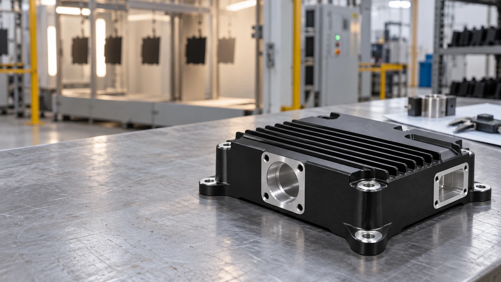
Powder-coated medical and industrial equipment chassis assembly made from SPCC sheet metal

CK Metal Tech publicly lists one automatic powder coating line and one manual powder coating line for large parts and large boxes within its automatic and manual powder coating capabilities. It also lists laser cutting, punching, bending, riveting, welding, grinding, and wire drawing for sheet metal work in stainless steel, carbon steel, silicon steel, aluminum alloy, galvanized sheet, and aluminum-zinc coated sheet.

Those capabilities establish a relevant manufacturing route, but the actual fit remains conditional. CK Metal Tech should verify the drawing, material, dimensions, weight, rack orientation, finish, masking, lot pattern, cure requirements, inspection plan, and packaging before confirming whether the automatic line, manual line, or a combined route is appropriate.

Conclusion

An automated powder coating line improves efficiency and consistency when repeat parts can move through stable loading, spray, cure, and inspection conditions without pushing delays into another process. It is less compelling when orders are small, highly mixed, oversized, frequently revised, or dominated by masking and manual access.

For a practical fit check, send the drawing, material, dimensions, weight, annual and lot quantities, color, texture, masked areas, critical interfaces, application environment, and packaging requirements. OEM teams can request a coating-line fit review from CK Metal Tech before fixing the production route in an RFQ.

FAQ

Does an automated powder coating line always produce a more consistent finish?

No. It can reduce variation in motion and timing, but consistency still depends on preparation, grounding, rack design, spray access, powder control, cure verification, maintenance, and inspection.

What types of sheet metal parts are good candidates for continuous coating?

Repeat panels, covers, brackets, and enclosure components with stable geometry, compatible colors, reliable hanging points, and predictable demand are often good candidates. The supplier must still verify size, weight, access, and cure behavior.

When should an OEM choose manual powder coating?

Manual or batch coating may fit prototypes, small mixed lots, frequent color changes, oversized assemblies, complex recesses, and parts requiring extensive masking or touch-up.

What information is needed for a powder coating RFQ?

Provide drawings, material, thickness, dimensions, weight, quantities, order pattern, color, gloss or texture, cosmetic surfaces, masked zones, critical interfaces, environment, inspection needs, and packaging requirements.

17th septembre 2026

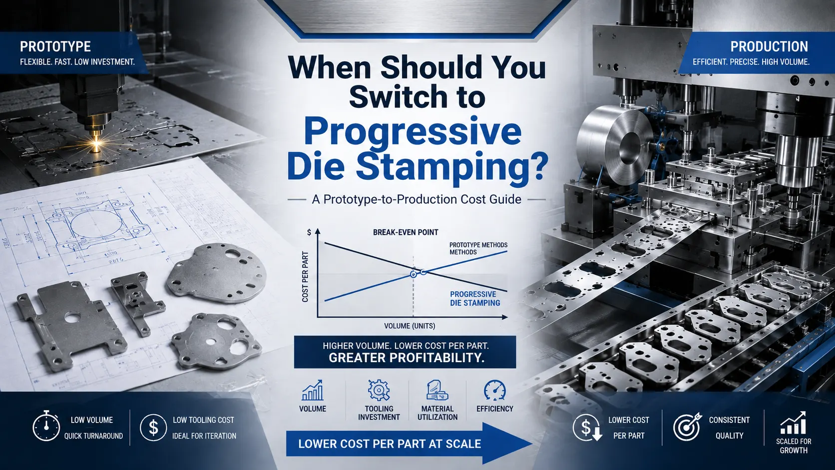
When Should You Switch to Progressive Die Stamping A Prototype-to-Production Cost Guide


When Should You Switch to Progressive Die Stamping A Prototype-to-Production Cost Guide

Switching from laser cutting or single-operation stamping to a progressive die is a production decision based on volume, geometry, material use, labor, and design stability. A progressive die stamping manufacturer can help compare these factors, but the buyer should understand the decision logic before requesting a quote.

The central question is not whether progressive stamping has a lower piece price. It is whether the tooling investment will reduce total lifecycle cost without creating excessive revision, quality, or maintenance risk.

Why Prototype-Friendly Processes Become Expensive in Production

Laser cutting and single-stage stamping are useful during prototyping because they require less dedicated tooling. They support frequent design changes and allow engineers to confirm fit, function, and assembly before the design is released.

Production introduces different cost drivers. Laser-cut parts may require separate bending, deburring, inspection, and handling. Single-operation stamping may involve several dies, manual transfers, repeated positioning, and additional work-in-process.

Hidden costs can include:

  • Manual loading and unloading
  • Multiple setups and die changes
  • Repeated part location and measurement
  • Handling between operations
  • Material scrap from inefficient blanking
  • Sorting, rework, and additional inspection
  • Delays caused by inconsistent process flow

Laser cutting may remain suitable for low-volume work, frequent revisions, large flat profiles, or early prototypes. A dedicated die is less suitable when demand is uncertain or the design has not reached a meaningful freeze point.

When Should You Switch to Progressive Die Stamping?

Production Volume and Run Rate

There is no universal production quantity that justifies a progressive die. The decision depends on tooling cost, the difference between current and projected unit cost, and the expected lifetime demand.

A stable part with recurring releases is a stronger candidate than a part ordered only occasionally. Review annual volume, monthly release frequency, forecast reliability, and the expected production life. High volume metal stamping can produce attractive unit economics, but only when demand is sufficient to recover the initial tooling expense.

Request separate figures for:

  • Die design and tooling
  • Material and expected scrap
  • Press operation
  • Secondary operations
  • Inspection and packaging
  • Maintenance and replacement items

A combined price makes it difficult to calculate the actual break-even quantity.

Part Geometry, Operations, and Material Form

Progressive stamping generally fits parts produced from strip or coil through a sequence of blanking, piercing, bending, forming, and cutoff operations. Repeated features and a predictable feed direction make the process easier to evaluate.

The design review should cover:

  • Number and sequence of operations
  • Strip width and material utilization
  • Hole-to-edge relationships
  • Bend direction and forming access
  • Flatness and positional requirements
  • Burr direction and allowable edge condition
  • Material grade and thickness

Parts with deep three-dimensional geometry, difficult forming behavior, or frequent design changes may require another process or a hybrid route. Material compatibility should be checked against the proposed progressive stamping dies and press setup. CK Metal Tech’s custom stamping tooling parts page can serve as a reference point when reviewing the range of components associated with stamping and tooling.

Design Stability and Revision Risk

Dedicated tooling should follow validation of critical interfaces and a reasonably stable design. A small hole-location change may require a limited modification, while a change to the part envelope, feed direction, or forming sequence can create more substantial rework.

A lower-risk transition is to use laser cutting or single-operation stamping during prototype and pilot builds, then release progressive tooling after the key dimensions have been verified. This approach helps prevent a die from being built before the production design is ready.

Progressive Stamping vs. Laser Cutting vs. Single-Stage Stamping

A meaningful comparison includes total cost, flexibility, and production risk.

Decision factor Laser cutting Single-stage stamping Progressive stamping
Design changes Highly flexible Moderate flexibility Higher revision risk
Tooling investment Low Low to moderate Higher upfront investment
Repetitive production May become labor-intensive May require multiple operations Strong fit for stable repeat production
Material utilization Depends on nesting Depends on blank design Depends on strip layout
Typical use Prototypes and low volume Small or medium repeat batches Stable production with recurring demand
Main risk Labor and cycle cost Handling and setup cost Tooling payback and maintenance

Progressive metal stamping is not automatically the right choice for every high-volume part. Critical features may still require machining, secondary forming, or additional inspection. The most economical solution may combine processes instead of replacing every operation with one method.

How to Calculate Progressive Die Tooling Payback

Break-Even Quantity Formula

The basic calculation is:

Break-even quantity =

Tooling investment /

Existing unit cost – Progressive unit cost

For example, if tooling costs $24,000, the current process costs $1.20 per part, and the projected progressive process costs $0.70 per part:

$24,000 / ($1.20 – $0.70) = 48,000 parts

The tooling begins to recover its cost after approximately 48,000 parts, before maintenance, scrap variation, financing, and secondary operations are included.

The comparison should use equivalent quality requirements and include:

  • Tool maintenance and spare components
  • Setup and changeover time
  • Scrap and rework
  • Secondary forming or finishing
  • Inspection labor
  • Packaging and handling
  • Expected engineering changes

This formula is a screening tool rather than a guaranteed financial result. Actual payback depends on the application and the assumptions used in the quotation.

Use Multiple Demand Scenarios

Calculate the payback period under conservative, expected, and high-demand forecasts. If the die only pays back under an optimistic scenario, retaining a flexible process may reduce commercial risk.

Repeat the calculation when material prices, part dimensions, release schedules, or annual demand change. A qualified progressive stamping supplier should identify which assumptions control the unit price and which figures remain provisional.

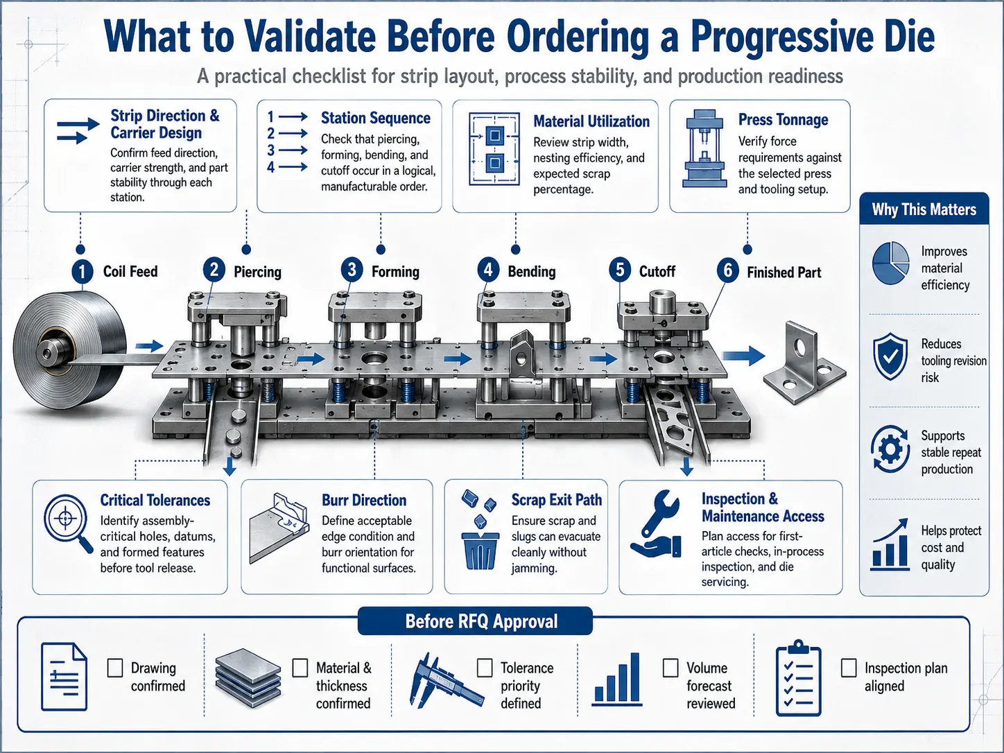
What to Validate Before Ordering a Progressive Die

Strip Layout and Station Plan

The strip layout affects material utilization, station count, feed stability, and scrap removal. It should show how the part moves through piercing, forming, bending, and cutoff operations.

Before approval, request confirmation of:

  • Strip direction and carrier design
  • Station sequence
  • Expected material utilization
  • Scrap exit path
  • Press tonnage requirement
  • Access for inspection and maintenance

A documented station plan also helps purchasing compare custom progressive stamping quotations on the same technical basis.

Critical Tolerances, Burrs, and Formed Features

Not every dimension requires the same control level. Assembly-critical holes, datums, contact areas, and formed features should be identified before tooling release.

The supplier should clarify:

  • Which dimensions are process-critical
  • How burr direction will be controlled
  • How springback or deformation will be checked
  • What inspection method will be used
  • How first-article approval will be documented

These checks reduce the risk of receiving parts that meet general dimensions but fail during assembly.


Progressive die stamping validation checklist showing strip layout, station sequence, material utilization, press tonnage, critical tolerances, burr direction, and scrap removal

How to Choose a Progressive Die Stamping Manufacturer

A capable supplier should connect tooling design, die manufacturing, press production, inspection, and production support. Equipment alone does not demonstrate that a supplier can manage the transition from prototype to repeat production.

CK Metal Tech publicly describes integrated CNC machining, sheet metal, stamping, tooling, and assembly capabilities. Its website lists precision punch presses ranging from 16 to 250 tons, with a published maximum speed of 500 strokes per minute. Publicly listed material coverage includes brass, phosphor bronze, beryllium bronze, nickel white copper, steel, stainless steel, plated strip, galvanized sheet, and spring steel. Actual suitability still depends on the specific drawing, material, thickness, and process plan.

The tooling equipment category also identifies wire EDM and surface-grinding equipment. A related progressive die stamping terminal strip provides a relevant product reference for buyers assessing continuous stamping applications.

When comparing progressive stamping services, request:

  • A drawing-based process review
  • Proposed strip layout
  • Separate tooling and piece-price quotations
  • Material and thickness confirmation
  • First-article and inspection plans
  • Maintenance and spare-part expectations
  • Clear assumptions behind the payback estimate

Conclusion

Progressive die stamping is worth evaluating when part geometry is stable, demand is recurring, multiple operations can be combined, and the expected lifecycle volume can recover the tooling investment. Laser cutting and single-operation stamping remain practical for prototypes, low-volume work, and designs that are still changing.

CK Metal Tech’s progressive die stamping and tooling services can be reviewed alongside the technical requirements for the part. For a project-specific assessment, submit the drawing, material, thickness, critical tolerances, target quantity, release schedule, and any available sample through request a stamping project review.

FAQ

What production volume justifies progressive die stamping?

No fixed quantity applies to every project. Calculate tooling investment divided by the unit-cost difference between the existing and progressive processes, then compare the result with realistic lifetime demand.

Is progressive stamping cheaper than laser cutting?

It may reduce unit cost for stable, repetitive production. Laser cutting can remain more practical for prototypes, low volumes, frequent revisions, or large flat parts.

How do you calculate progressive die payback?

Divide the tooling investment by the difference between the current unit cost and the projected progressive unit cost. Include maintenance, scrap, inspection, and secondary operations for a more useful estimate.

What should be included in a progressive stamping RFQ?

Include 2D and 3D drawings, material grade, thickness, annual quantity, release schedule, critical tolerances, surface requirements, inspection expectations, packaging, and samples when available.

How do you choose a progressive stamping supplier?

Compare die design, press capability, material experience, inspection planning, maintenance support, and the ability to manage tooling, tryout, first-article approval, and repeat production.

11th septembre 2026

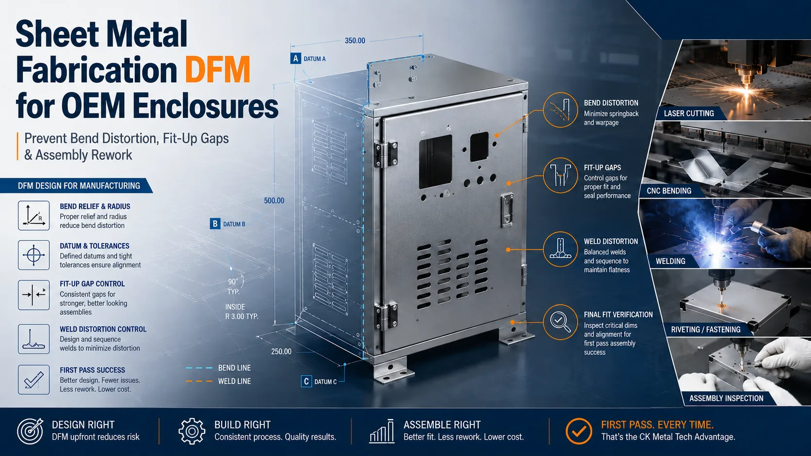
Sheet Metal Fabrication DFM for OEM Enclosures Preventing Bend Distortion, Fit-Up Gaps and Assembly Rework


Sheet Metal Fabrication DFM for OEM Enclosures Preventing Bend Distortion, Fit-Up Gaps and Assembly Rework

For an OEM enclosure, a drawing can be dimensionally correct and still fail on the assembly line. The usual causes are predictable: bend allowance assumptions that do not match the press brake process, holes placed in unstable bend zones, weld shrinkage that moves a datum, or a tolerance stack-up that leaves visible fit-up gaps. Sheet metal fabrication DFM works when the enclosure is designed around the manufacturing and assembly sequence, not just the flat pattern.

This guide gives engineers and sourcing teams a review path for formed and welded enclosures used in industrial automation, electrical equipment, medical equipment, and OEM products. Material, dimensions, loads, finish, and inspection capability must still be confirmed against the specification.

Why Enclosure DFM Must Start Before the Flat Pattern

An enclosure is a system of interfaces: panels meet at flanges, doors locate against frames, fasteners clamp surfaces, and brackets position electronics. A small flange error can become a large opposite-corner gap. A hole accurate in the flat state can shift after bending, while coating on a grounding or mating surface adds another variable.

Separate functional dimensions from appearance dimensions. Function controls gasket compression, connector alignment, PCB mounting, door closure, rail position, and grounding continuity; appearance controls reveal and visible alignment. Give each group a realistic tolerance and inspection method rather than tightening every edge.

A supplier review is most useful when the design is still flexible. CK Metal Tech lists laser cutting, CNC punching, bending, riveting, welding, grinding, and related operations in its precision sheet metal manufacturing capabilities. That process breadth supports a DFM conversation about sequence, access, fixturing, and inspection before a production route is locked.

Build the Design Around Datums and Bend Behavior

Choose a stable datum scheme

Select primary, secondary, and tertiary datums that can be located repeatedly during cutting, bending, welding, coating, and inspection. Prefer datums accessible after assembly. If a door, lid, or internal rail controls function, reference it from the same scheme used to inspect the body. Avoid dimensioning a critical hole from unrelated outside edges, which hides tolerance accumulation.

Review the flat pattern and formed state together

The flat pattern controls cut features, but the formed state controls fit. Check bend direction, inside radius, flange length, relief geometry, corner notches, and tool access in 3D. Features near a bend may distort, lose perpendicularity, or become hard to reach. Move a hole into a stable flat region, add a relief, or define a secondary operation instead of assuming the nominal location will survive forming.

  • Identify dimensions that apply before finishing and dimensions that apply after finishing.
  • Call out bend angle, inside radius, and angle tolerance for every functional bend.
  • Use reliefs and corner notches to prevent tearing, bulging, and trapped material.

Prevent Bend Distortion Through Process-Aware Geometry

Bend distortion is not solved by laser-cut precision alone. It depends on material grade, thickness, rolling direction, tooling, springback, bend sequence, and material removed near the bend. Ask what the press brake can support consistently and how the part will be located for each hit.

For long panels, distribute bends so the part stays supported and the sequence does not trap the tool. Keep narrow flanges wide enough for the tooling and avoid opposing bends that make the final hit inaccessible. Use formed returns or ribs for a broad face that must stay flat. Confirm bend-table and springback assumptions for stainless steel, carbon steel, aluminum, galvanized, or aluminum-zinc sheet instead of copying another grade.

After first-article bending, inspect squareness, flange distance, hole pattern, panel flatness, and door reveal. Record the process condition; a corrected bend program is more robust than manual rework.


Curved sheet metal enclosure with bending welding and powder coating

Control Fit-Up Gaps in Welded and Fastened Assemblies

Design the joint for its real purpose

Use welding for structural continuity, sealing, or permanent alignment; use rivets, clinch hardware, or screws where serviceability matters. Each joint changes the tolerance stack-up. Removable panels improve access but add alignment, coating, and grounding variables. Define which surfaces locate the part and which fasteners only clamp it.

Welding introduces heat and shrinkage. Long welds on thin panels can pull a flange out of plane, while an inconsistent gap changes penetration and appearance. Use a fixture tied to functional datums, a balanced sequence, and tack locations that hold geometry. Keep sealing or precision surfaces out of the heat path, or plan a justified post-weld operation.

CK Metal Tech’s published sheet metal scope includes robotic, laser, TIG, and gas-shielded welding for listed steel, stainless steel, and aluminum applications. The correct process remains conditional on thickness, joint design, access, appearance, and required inspection. A supplier should confirm the weld sequence and datum-control plan during the review, not after a fit-up problem appears.

Validate Assembly Before Release to Production

Use a physical prototype to test the interfaces that CAD cannot prove

Prototype validation should include the body, doors, hinges, latches, fasteners, gaskets, brackets, connectors, and representative electronics. Check closure force, screw engagement, door reveal, gasket contact, cable routing, and removal path. A cosmetic sample without real hardware can hide a collision or tolerance stack-up.

  1. Measure the primary datums and assembly-critical interfaces before coating.
  2. Repeat the checks after welding, grinding, painting, or powder coating.
  3. Record the worst-case fit, not only the average sample, and update the drawing or fixture accordingly.

Surface treatment is part of DFM, not a final cosmetic decision. CK Metal Tech offers powder coating and painting routes, including manual lines for large parts and boxes, so the RFQ should identify masked threads, grounding zones, gasket seats, and no-coat surfaces. Coating thickness and surface preparation may vary by material, finish, and configuration; verify the finished assembly where fit or electrical continuity matters.

Make the RFQ Carry the DFM Decisions

A comparable quote needs more than a 3D file. Include the 2D drawing, material and thickness, bend radii and angle tolerances, weld symbols, hardware, finish, masking map, inspection points, quantities, and shipping orientation. State whether alternate bend sequences, reliefs, joint types, or material substitutions may be proposed.

Ask how the supplier will control the features that matter to assembly. Useful questions include: Which datums are used in the bending fixture? How is weld distortion checked? Which dimensions are measured after finishing? How are first-article changes documented? What evidence is provided for a prototype fit check? The OEM/ODM engineering and manufacturing service is relevant when these decisions need to be coordinated across cutting, forming, joining, finishing, and assembly.

A practical supplier scorecard should weight technical communication and corrective-action discipline alongside price. CK Metal Tech describes quality activities including APQP, PPAP, PFMEA, process audits, 5M management, MES, and 8D problem solving. Those systems do not replace part-specific evidence, but they are useful indicators that design changes and nonconformances can be handled through a controlled process.

Conclusion

The most reliable OEM enclosures are designed around the full chain from flat sheet to finished assembly. Establish datums early, keep critical features out of unstable bend zones, plan a balanced weld sequence, and validate the coated assembly with real hardware. When the RFQ records those decisions, a fabricator can quote the same functional requirement the OEM is trying to build. For a project-specific review, contact the technical team with the drawing, material, thickness, quantity, finish, and the interfaces that must fit on the first build.

FAQ

What is the most common DFM cause of enclosure fit-up gaps?

Tolerance stack-up combined with bend-angle variation is a common cause. Weld shrinkage, coating buildup, and locating a feature from the wrong datum can make the gap worse.

Should holes be added before or after bending?

Most holes are cut before bending, but features that require a formed-state relationship may need a secondary operation. The choice depends on access, distortion risk, volume, and the required positional tolerance.

How can a welded enclosure stay square?

Use functional datums in the fixture, controlled tack locations, a balanced weld sequence, and an inspection plan that checks squareness and flange position after welding. Thin sections may need additional support or a different joint strategy.

Does powder coating affect assembly fit?

It can. Threads, gasket seats, grounding zones, and sliding or mating surfaces should be masked or otherwise specified, then checked on the finished part.

What should an OEM send for a DFM review?

Send the latest 2D drawing and 3D model, material and thickness, annual and pilot quantities, finish, critical interfaces, operating environment, assembly hardware, and any fit, sealing, grounding, or inspection requirements.

10th septembre 2026
Maison
WhatsApp
E-mail
Contacts