







28th August 2026
Robot Components Manufacturing Guide: CNC Machining vs Sheet Metal Fabrication vs Metal Stamping
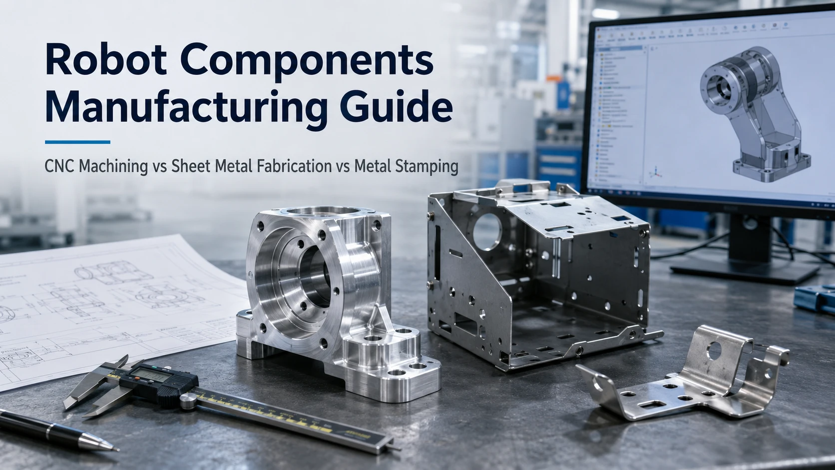
Choosing the right process for robot components manufacturing starts with the part, not the machine. A compact joint housing, a thin-wall chassis, and a repeat-production clip may belong to the same robot but require different manufacturing routes. Engineers and sourcing teams should compare geometry, stock form, critical interfaces, design maturity, production demand, secondary operations, and inspection needs before choosing CNC machining, sheet metal fabrication, metal stamping, or a hybrid process.
CNC Machining vs Sheet Metal vs Stamping for Robot Components: How to Choose
Start by asking whether the part is fundamentally a solid three-dimensional component, a fabricated sheet structure, or a thin repeatable formed part. Then review precision, design stability, and expected demand. CK Metal Tech’s existing process guidance similarly treats geometry, stock form, design maturity, critical features, and expected production demand as key process-selection inputs.
| Project condition | CNC machining | Sheet metal fabrication | Metal stamping |
|---|---|---|---|
| Solid, complex 3D geometry | Strong fit | Limited | Usually unsuitable |
| Large thin-wall chassis or enclosure | Often inefficient | Strong fit | Depends on geometry/tooling |
| Precision bores, datum faces, threads | Strong fit | May need secondary CNC | May need secondary CNC |
| Frequent design changes | Flexible | Flexible | Tooling risk |
| Stable repeat production | Review total cost | Strong for fabricated structures | Strong candidate if tooling is justified |
Start With Part Geometry and Material Form
Bar, plate, or block stock points toward machining when the component needs deep features, bearing seats, threads, several working planes, or closely related datums. A chassis, cover, enclosure, or frame made from consistent sheet thickness is usually a better sheet metal candidate. Stamping becomes relevant when geometry can be blanked, pierced, bent, formed, or drawn from sheet or coil and repeated with stable tooling. CK Metal Tech’s existing CNC-to-stamping guidance also starts by separating solid stock geometry from parts that can be produced from sheet or coil.
Then Check Precision, Design Maturity, and Production Demand
Not every dimension on a robot drawing deserves the same process capability. Bearing locations, motor interfaces, alignment datums, shafts, and sensor mounting features may control function, while covers and noncritical edges can often use more flexible tolerances.
Design maturity is equally important. CNC machining and laser cutting with bending are easier to revise while a robot design is changing. Dedicated stamping dies carry more revision risk. There is no universal production quantity at which stamping automatically becomes economical; tooling, geometry, secondary work, material behavior, and lifetime demand all affect the decision.
When Is CNC Machining the Right Choice for Robot Components?
Use CNC for Precision Interfaces and Complex 3D Components
CNC machining fits robot components that depend on controlled three-dimensional geometry, such as joint housings, shaft-related parts, motor mounting interfaces, bearing seats, machined datums, or multi-plane threaded features. It is also useful during prototype and pilot stages because design changes do not require a dedicated forming die. CK’s published process comparison identifies prototypes, changing designs, solid geometry, precision bores, threads, and datum faces as conditions that can favor machining.
When requesting CNC machining for robot components, identify functional datums and critical interfaces instead of tightening every dimension. Confirm how the workpiece will be located, which features can remain in one setup, whether grinding or finishing follows machining, and how assembly-critical geometry will be inspected.
Know When CNC Machining Becomes an Expensive Route
Machining can be inefficient when large amounts of stock must be removed to create a simple thin-wall structure. A robot enclosure, cover, or broad mounting structure may be better suited to cutting and bending if only a few areas require high precision.
In that situation, separate the base structure from the precision interfaces. A fabricated or stamped body can create most of the geometry while CNC is reserved for bearing bores, datum faces, threads, or other critical features. CK’s current process guidance also recognizes stamped-base-plus-machined-critical-feature routes where forming can create the main geometry but precision interfaces still require secondary work.
When Is Sheet Metal Fabrication Better for Robotics?
Use Sheet Metal for Chassis, Covers, Enclosures, Frames, and Brackets
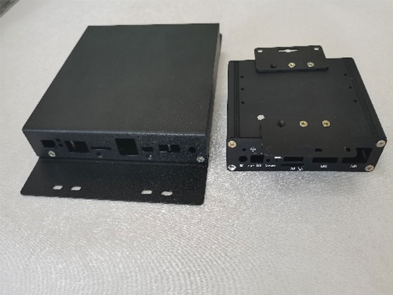
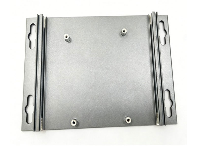
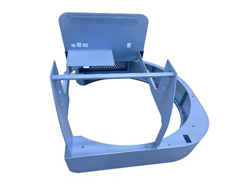
Sheet metal fabrication is a strong candidate for structures made from relatively consistent wall thickness: robot chassis, equipment covers, control enclosures, mounting frames, panels, and structural brackets. Cutting, punching, bending, riveting, and welding can build these forms without machining them from solid stock.
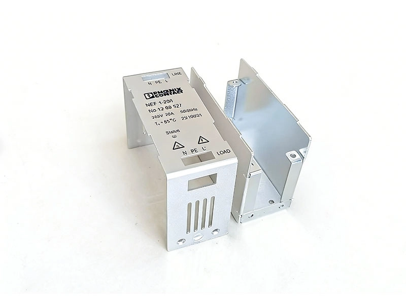
For sheet metal fabrication for robotics, define material, thickness, bend geometry, joining method, finish, critical interfaces, and assembly requirements. CK Metal Tech publicly lists laser cutting, CNC punching, bending, riveting, and welding within its sheet metal capability, and industrial automation is among the applications stated on the site.
Control Bend Accuracy, Welding Distortion, and Datum Stack-Up
A fabricated assembly can create fit problems even when its individual pieces are acceptable. Bend variation, welding distortion, tolerance accumulation, or finishing on mating areas may shift motor, sensor, or mounting interfaces.
Mark important datums before production and decide which dimensions need post-weld inspection. Fixture design, welding sequence, heat input, and early design review can affect dimensional stability in welded sheet structures. Where a bearing or motor interface must remain tightly controlled, post-fabrication machining may reduce assembly risk.
When Does Metal Stamping Make Sense for Robot Components?
Use Stamping for Thin, Repeatable, Feature-Dense Components
Metal stamping becomes attractive when a robot component uses sheet or coil, has stable geometry, and will repeat enough to justify tooling. Possible candidates include retainers, clips, shields, thin brackets, spring features, shims, sensor flags, and parts combining holes, tabs, bends, or formed details.
Stamping does not mean every feature must come directly from the die. Tapping, drilling, machining, coating, or assembly may remain necessary; CK’s published process guidance specifically notes that precision bores, threads, bearing locations, datum faces, and similar features can remain secondary operations. When evaluating metal stamping and tooling for robot components, confirm material and thickness, forming feasibility, burr-sensitive surfaces, critical dimensions, secondary operations, revision status, and expected program demand.
Do Not Commit to Stamping Tooling Before the Design Is Stable
Production tooling becomes risky when joint geometry, mounting interfaces, material thickness, or customer requirements are still changing. Late revisions can require die modification and another round of trials and sample approval.
Prototype validation and DFM should therefore happen before hard-tool release. Before tooling approval, CK’s existing guidance recommends confirming material, thickness, interfaces, critical dimensions, finish, drawing revision, and expected demand rather than relying on a fixed volume rule. Purchasing teams should also account for tooling maintenance, secondary operations, inspection, finishing, and possible modification costs.
When Is Hybrid Manufacturing Better Than a Single Process?
Combine Fabrication or Stamping With CNC for Critical Features
Robot components do not have to fit one process exclusively. A welded structure can be machined afterward to establish a motor datum or bearing interface. A stamped base can receive drilling, tapping, reaming, milling, or grinding where the functional requirement exceeds what forming should control.
A hybrid route makes sense when fabrication or stamping creates most of the geometry and a short secondary operation controls only critical features. It becomes less attractive when nearly every surface still needs machining or forming variation prevents repeatable fixturing. The same principle appears in CK’s existing CNC-to-stamping guidance, where a stamped base can be combined with secondary machining for precision features.
Common Robot Component Manufacturing Mistakes and How to Prevent Them
Avoid Over-Machining, Over-Tolerancing, and Premature Tooling
Three errors create avoidable cost: machining a thin structure from solid stock when fabrication could perform the function, applying tight machining-style tolerances to every fabricated or stamped feature, and approving production dies before the design is stable.
A useful DFM review classifies features as function-critical, assembly-critical, or noncritical. It then matches each feature to the stock form and manufacturing process that creates it most naturally. Precision machining or special inspection should be reserved for requirements that affect performance or assembly.
What Should Be Included in a Robot Components Manufacturing RFQ?
Give the Supplier Enough Information to Recommend the Manufacturing Route
Send the current 2D drawing and STEP model, material and stock form, part function, critical datums and tolerances, prototype quantity, expected repeat demand, finish, inspection requirements, mating components, assembly conditions, and revision status. For tooling projects, state expected program demand and whether the design is frozen. CK’s published sourcing guidance similarly calls for current drawings, STEP files, material, quantities, critical tolerances, secondary operations, finishing, and inspection requirements when comparing routes.
Also identify where process changes are acceptable. This gives the supplier room to propose a fabricated body with machined datums or move a stable thin component toward stamping without changing the functional requirements.
How to Choose a Robot Components Manufacturing Supplier
Compare Process Selection, DFM, Inspection, and Multi-Process Capability
A supplier should explain why the proposed process fits the component and what would justify a different route. Compare DFM feedback, material capability, tooling responsibility, machining and forming resources, secondary finishing, inspection planning, revision control, and assembly coordination—not only unit price.
CK Metal Tech lists machining, sheet metal processing, metal stamping, tooling design and manufacturing, surface finishing, and component assembly within its integrated precision metal manufacturing capabilities. That combination is relevant when one robot assembly contains machined interfaces, fabricated structures, stamped parts, and secondary operations that must work together.
The actual drawing still controls the decision. CK Metal Tech should be evaluated against the component’s geometry, tolerances, volume, finish, inspection, and assembly requirements rather than a capability list alone.
Conclusion
Robot components manufacturing works best when process selection follows geometry first, then critical precision, design maturity, production demand, and secondary operations. CNC suits many solid and precision-interface components; sheet metal fits many chassis, covers, frames, and brackets; stamping suits stable repeat formed parts; and hybrid routes can combine them.
For a process review, prepare the drawing, 3D model, material, critical dimensions, application, finish, prototype and production quantities, and inspection needs. Buyers can contact CK Metal Tech to discuss manufacturability without assuming that one process is automatically the right choice.
FAQs About Robot Components Manufacturing
Which robot components are usually CNC machined?
Parts with complex 3D geometry, precision bores, threads, bearing locations, motor interfaces, or important datum relationships are common CNC candidates. Material, tolerances, quantity, and secondary requirements still need review.
Is sheet metal fabrication suitable for robot chassis and enclosures?
Yes, when the structure uses relatively consistent sheet thickness and can be cut, bent, riveted, or welded. Precision motor or bearing interfaces may still require secondary machining.
When should a robot component move from CNC or laser cutting to stamping?
Consider stamping when the geometry suits sheet or coil forming, the design is stable, and repeat demand can justify tooling and validation. There is no universal quantity threshold.
Can one robot component use both stamping and CNC machining?
Yes. Stamping can create the base geometry while machining, drilling, tapping, reaming, or grinding completes critical interfaces. The hybrid route should be evaluated as a complete manufacturing process rather than by press cost alone.
Leave a reply