
創開

1 l 1 n d

ロード中


プレス加工および金型加工

お問い合わせ
  • //
  • 製品 //
  • プレス加工および金型加工

ベクター

よくある質問

お問い合わせ写真

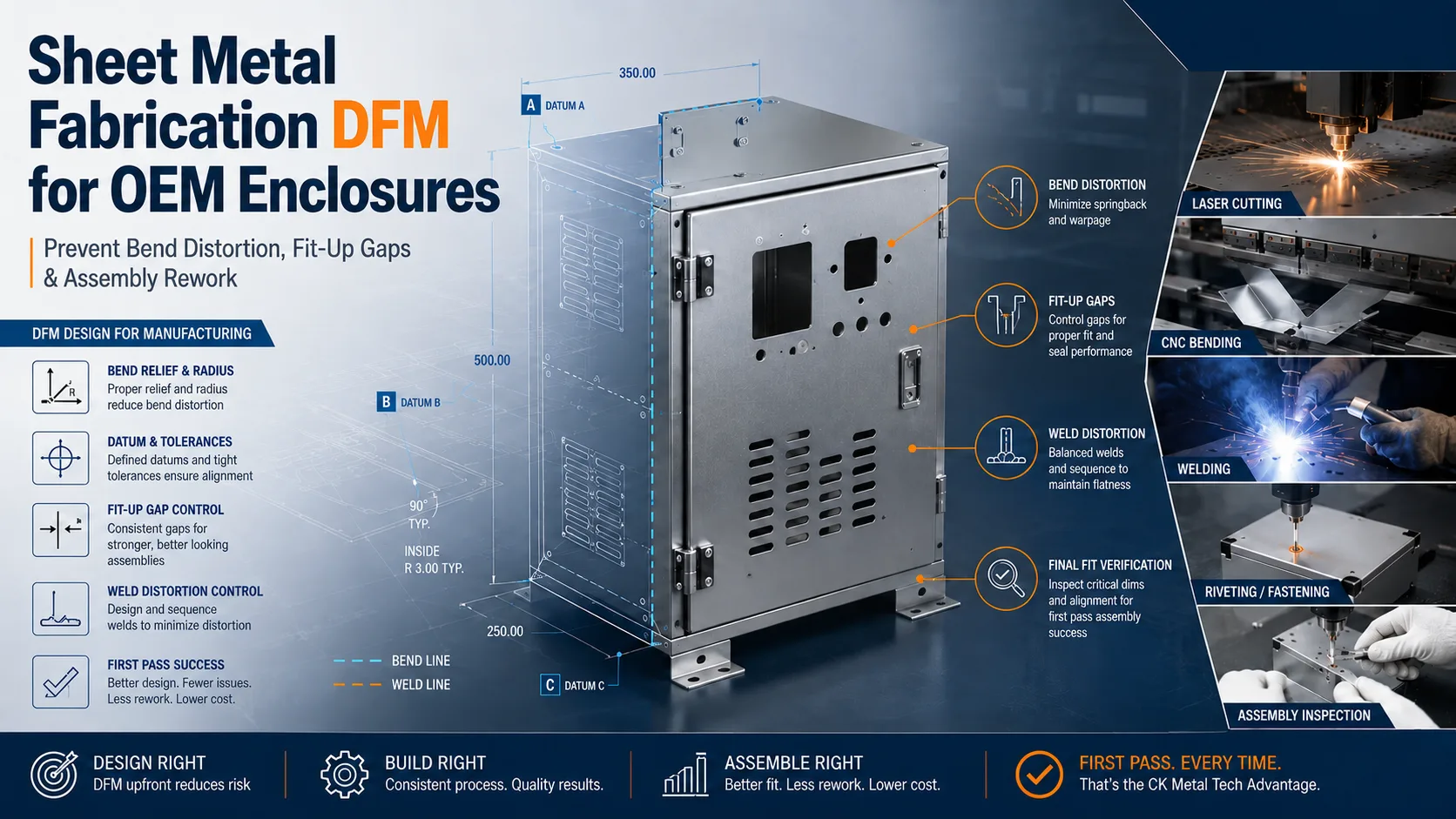
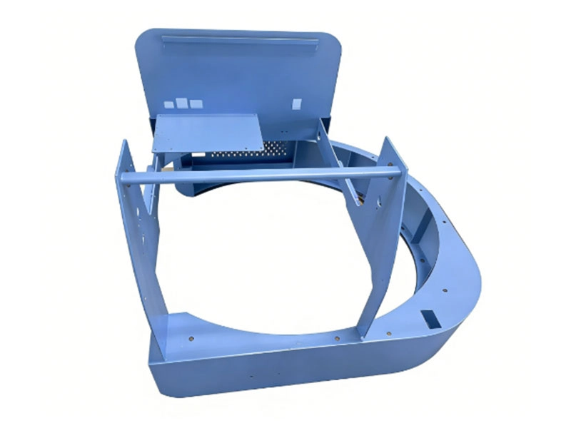
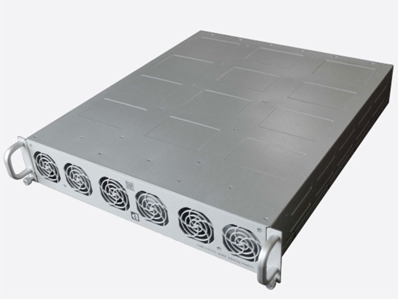
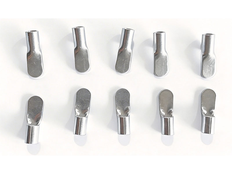
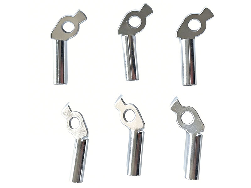
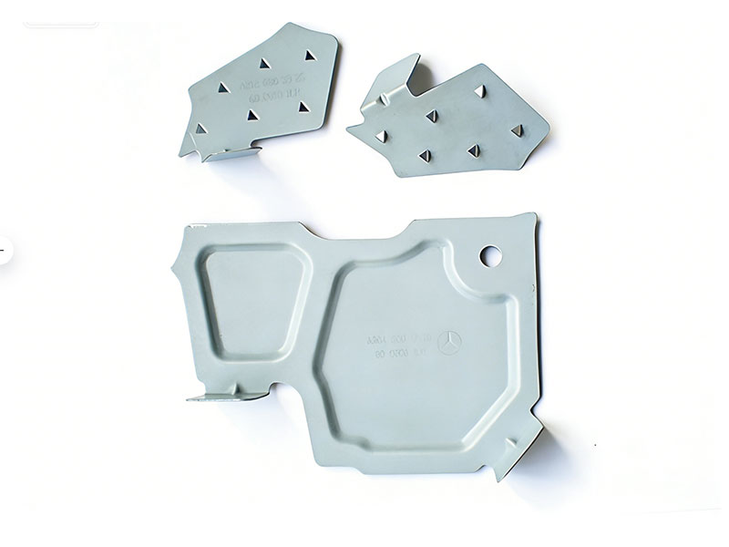
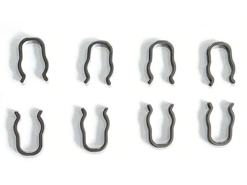
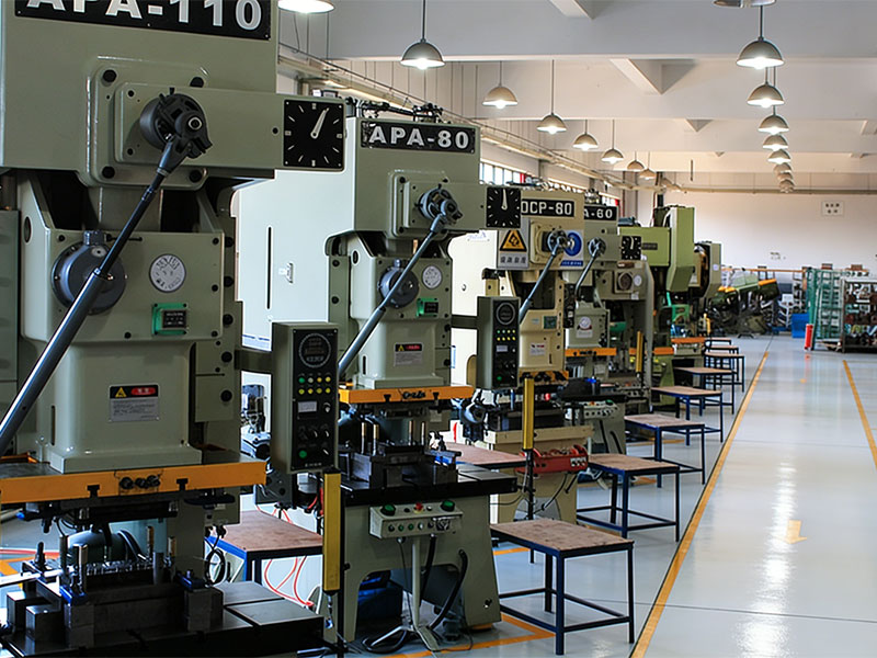
精密プレス加工部品は、高精度金型を用い、プレス加工工程における単一ステーションでの型締めと位置決めによって製造されます。プレス加工機におけるワークピースの寸法精度と位置公差には厳しい要求が課されるため、金型研磨、熱処理、表面処理、組立といった厳密な仕上げ工程が不可欠です。これらの部品は通常、少量生産または個別部品として製造されるため、生産量は比較的少なく、結果として機械に対する要求はそれほど厳しくありません。 プレス加工では、材料は金型の隙間を通って金型キャビティに流入します。圧力下で、材料は分離または塑性変形を起こし、所望の形状と構造を実現します。圧力解放後、制御された成形工程を経て完成品が得られます。このため、プレス加工は古典的な冷間引抜き加工技術と言えます。実際の生産においては、製品品質の確保、効率の向上、廃棄物の削減、省エネルギーのために、製造業者は通常、以下の戦略的な対策を実施します。 1. 適切な工具の使用 2. 原材料の適切な選択 3. 適切な工程規則の策定 4. 作業員の技術研修を改善する。 5. 機械の自動化を改善する。 6. 作業環境を改善する。 プレス加工部品製造の特徴: (1) 材料利用率が高い。 (2) 比較的薄い板材から複雑な製品を製造できる。 (3) 構造柱を含む様々な構造に加工できる。 (4) 厚肉中空構造を成形できる。 (5) 大面積の板材を加工できる。 (6) 機械化が容易である。 (7) 機械化と自動化の完了が容易である。 (8) システムの構築が容易である。

精密機械部品の製造は、一般的に精密機械用の部品加工を伴い、極めて高い精度が求められます。そのため、精密機械部品の加工に必要な材料特性や一般的な加工技術を理解することに加え、製造工程全体を把握することが不可欠です。以下では、精密機械部品製造の5つの工程について概説します。 1. 粗加工 生産性向上が最重要課題です。各面の加工能力の大部分を除去し、基準面を形成します。 2. 中仕上げ加工 粗加工後に発生する可能性のある欠陥を除去し、一次面と二次面を同時に加工します。仕上げ加工の準備を容易にし、適度な仕上げ能力を確保するために、一定の加工精度を達成する必要があります。 3. 仕上げ加工 仕上げ加工では、中仕上げ加工で残った加工能力を除去するために、通常、大きな切削量、小さな送り量、小さな切削深さを用い、精密機械部品の表面が図面の技術基準を満たすようにします。 4. 研磨 主に表面粗さの低減や加工面の強化を目的としており、高い表面粗さが要求される表面加工に用いられます。 5. 超精密加工 一般的に、精密穴あけ、精密鏡面切削、精密研削、研磨といった工程を経て、ワークピースの加工精度は0.1~0.01μm、表面粗さRaは0.001μm以下となります。 機械部品の5段階精密加工工程は、粗加工から精密加工へと段階的に精度を高めていきます。この体系的なアプローチにより、お客様のニーズに応じた仕様を満たす部品を製造します。Yuntuo Machiningは精密機械部品製造を専門としています。お客様からご提供いただいた図面や材料に基づき、カスタマイズサービスを提供し、お客様のあらゆる期待に応える精密加工部品をお届けします。

無料で送ってください
メッセージ


    最近の
    ブログ記事

    How to Control Runout in Long Shaft Machining: Setup, Grinding, and Inspection for Parts Up to 4 Meters

    07
    8月


    How to Control Runout in Long Shaft Machining Setup, Grinding, and Inspection for Parts Up to 4 Meters

    Long shaft machining becomes difficult when a part passes diameter inspection but still shows excessive runout, bow, taper, vibration, or assembly misalignment. The cause may begin in the raw material, appear during stock removal, develop after heat treatment, or result from an inspection setup that does not reproduce the drawing datum. For shafts approaching four meters, material condition, workholding, machining sequence, grinding, inspection, and packaging must form one controlled process.

    Long Shaft Machining Runout: Diagnose the Pattern First

    Runout is commonly checked by rotating the shaft through 360 degrees and comparing the indicator’s maximum and minimum readings at a specified position. The result is meaningful only when the datum, support method, gauge position, and permitted value are defined.

    Observed condition Check first Next action
    Runout is concentrated near one end Center holes, chucking, tailstock, datum transfer Verify the setup axis
    Maximum bow appears near the middle Support spacing, stock straightness, cutting force Review support and roughing
    Diameter changes along the shaft Tailstock alignment, tool wear, thermal drift Separate geometric and thermal error
    Runout increases after heat treatment Residual stress, support, remaining allowance Recheck straightness before finishing
    Inspection reports disagree Datum, support points, orientation, gauge position Agree on one method

    This identifies whether the next review should focus on material, setup, grinding, or measurement.

    Why Long Shafts Develop Runout, Taper, and Straightness Errors

    Material Straightness, Residual Stress, and Heat-Treatment Distortion

    A long bar may contain initial bow or uneven residual stress. Heavy material removal can release that stress and move a shaft that appeared straight during roughing. Thin sections, keyways, and large diameter changes increase the risk.

    For parts requiring substantial stock removal or heat treatment, a staged route may be safer than machining directly to final size. Rough turning establishes the geometry, followed by a stability or heat-treatment step when specified, another straightness check, and finish machining. Remaining allowance should be distributed so final turning or grinding does not need to correct most of the error from one side.

    The RFQ should identify material grade, supply condition, heat treatment, hardness, and incoming straightness requirements.

    Cutting Force, Unsupported Length, Clamping, and Heat

    A slender shaft deflects under radial cutting force. As unsupported length increases, the tool may push the workpiece away, causing taper, barrel shape, chatter, or inconsistent diameter. Excessive chuck, tailstock, or steady-rest pressure can also bend the shaft before cutting.

    Lower cutting force, short tool overhang, staged passes, controlled support, and temperature management reduce risk. A strategy that works on a rigid section may fail at the smallest diameter. Buyers should ask how the supplier will support that section, manage tool wear and thermal growth, and perform in-process checks.

    Choosing the Right Setup for Long Shaft Turning

    The setup should reflect shaft length, diameter, weight, material, critical datums, and permitted runout. Buyers can review CK Metal Tech’s long shaft CNC machining and grinding capabilities before submitting a drawing.

    Between-Centers Turning and Tailstock Alignment

    Turning between centers can preserve one rotational axis through several operations when center holes remain available as process datums. It is useful when multiple journals must relate to the same axis, although end geometry, weight, or feature access may require another setup.

    Center holes must be prepared and protected because inconsistent seating transfers into runout. Tailstock alignment and thrust also matter: insufficient support permits movement, while excessive force may bow a slender shaft. The supplier should check initial indicator readings, explain how the part will be reloaded, and confirm whether center holes are temporary process features or drawing-controlled features.

    Steady Rest vs. Follow Rest

    A steady rest supports the shaft at a fixed position; a follow rest moves with the cutting tool. The correct choice depends on where the unsupported span develops.

    Official machine guidance describes steady rests as support for long or narrow shafts and instructs operators to adjust rollers without causing workpiece deflection. It also recommends rotating the part and checking it with an indicator after adjustment.

    Rollers that are too loose provide little control; rollers that are too tight can create friction, marks, heat, or artificial bending. The supplier should identify support locations and explain how alignment will be rechecked after repositioning.

    Machining Sequence for Controlling Long-Shaft Runout

    Rough Turning, Stability Review, and Finish Turning

    A sound process separates heavy stock removal from final geometry control. Rough turning establishes the shape and reveals how the blank responds as material is removed. The shaft can then be checked for bow and datum movement before heat treatment, semi-finishing, or grinding.

    A typical route is:

    Material review → datum preparation → rough turning → stability or heat-treatment step → straightness review → semi-finishing → finish turning or grinding → final inspection.

    The exact route depends on material, geometry, hardness, and drawing requirements. Repeated chucking should be minimized or controlled through consistent center holes, journals, or other process datums.

    When Grinding Is Required—and When Turning Is Enough

    Grinding may suit hardened journals, bearing fits, wear surfaces, or requirements involving surface condition, roundness, cylindricity, and relationships between diameters. It should not be added automatically. If finish turning meets the drawing, another setup may add cost and datum-transfer risk.


    Precision shaft components manufactured with CNC turning and grinding processes for long shaft machining applications

    For ground shafts, confirm the grinding datum, support method, allowance, heat-treatment sequence, and equipment range. CK Metal Tech’s 精密旋削加工されたシャフト部品と研削加工 use a published route combining precision turning, grinding, and quenching for custom alloy-steel or stainless-steel designs.

    This product does not establish a four-meter grinding range. Maximum length, diameter, weight, and geometry must be verified for each drawing.

    How to Inspect Runout and Straightness on a Long Shaft

    Define the Datum Axis Before Selecting the Gauge

    Circular runout, total runout, straightness, roundness, and coaxial relationships describe different conditions. A shaft may meet diameter tolerance while failing rotational function. The drawing should identify the functional datum axis and the characteristic that affects assembly.

    The datum may come from center holes, two bearing journals, or another functional feature. Measuring one section does not prove the complete shaft meets total runout or straightness requirements. Reports should state the datum, support method, gauge positions, orientation, rotation method, and result.

    Control Gravity Sag and Measurement Support

    A long slender shaft can sag under its own weight during horizontal inspection. Between-centers measurement, rollers, V-blocks, and coordinate measurement systems may produce different readings if support positions and datums are not correlated.

    Inspection equipment must match the workpiece envelope, weight, access, and required uncertainty. A CMM may suit some features, but it should not be assumed that every machine can accommodate a complete four-meter shaft. Supplier and buyer should agree on support spacing, orientation, rotation method, and measurement correlation.

    CK Metal Tech has CMM, 2.5D measurement, metallographic, and hardness-testing resources, but the method for a full-length four-meter shaft must be confirmed against the equipment range.

    Troubleshooting Long-Shaft Machining Defects

    Runout near one end points first to the chuck, center hole, tailstock, or datum transfer. Maximum bow near the middle suggests stock straightness, support spacing, cutting force, or stress release. Gradual taper calls for checks of alignment, tool wear, machine geometry, and temperature. Periodic chatter may indicate poor rigidity, unsuitable speed, excessive tool overhang, or unstable rest contact.

    If runout increases after heat treatment, verify straightness before removing final allowance. If grinding introduces new error, review grinding heat, support pressure, wheel condition, and datum correlation. Rework should not begin until the cause and remaining allowance are understood.

    RFQ Checklist for Long Shafts Up to 4 Meters

    Drawing, Material, and Application Data

    Provide the current 2D drawing and 3D model, total and effective machining lengths, maximum and minimum diameters, estimated weight, material grade and condition, center holes, functional datums, and all stepped, threaded, tapered, keyed, or drilled features.

    State circular runout, total runout, straightness, surface requirements, heat treatment, hardness, grinding scope, and inspection records. Application details such as speed, load, mating components, and environment help identify critical features. Include quantities and any photographs or reports from an existing defect.

    Capacity, Inspection, and Packaging Questions

    Ask the supplier to confirm usable between-centers length, maximum diameter and weight, lifting method, tailstock and rest configuration, and which turning, heat treatment, grinding, and inspection stages are internal or outsourced. Confirm grinding range rather than assuming it matches turning capacity.

    The quotation should identify datum simulation, inspection supports, sample and production setups, and packaging. A shaft that passes inspection can still bend if supported incorrectly during storage or transport.

    How to Choose a Long Shaft Machining Supplier

    Evaluate the Complete Manufacturing Route

    A suitable supplier should explain how material review, datum preparation, roughing, support, heat treatment, finishing, grinding, inspection, and packaging connect. The review should identify where straightness is checked, how setups are repeated, which features establish the final axis, and what happens if the shaft moves after heat treatment.

    Buyers should confirm whether first articles and production parts use the same route, which records are available, and how abnormal results are handled. Confirming machine length without discussing weight, support, grinding, and inspection is not a complete feasibility review.

    Relevant CK Metal Tech Capabilities

    Zhejiang Chuangkai Mechanical and Electrical Technology Co., Ltd. connects machining with related processes through its 精密金属加工の統合能力. Buyers can also review 浙江創凱機電科技有限公司について when evaluating the supplier.

    Confirmed resources include 18 precision CNC lathes, turning capacity for workpieces up to approximately four meters, internal and external cylindrical grinding, centerless grinding, thread rolling, tapping, and drilling. CK Metal Tech also holds IATF 16949 certification, while its website presents machining, stamping, sheet-metal fabrication, surface treatment, and assembly as connected services.

    Maximum diameter, weight, grinding length, support arrangement, and achievable runout or straightness must still be verified for each project.

    結論

    Controlling runout in long shaft machining requires more than a long-bed lathe. Material condition, datums, support pressure, cutting force, heat treatment, grinding, inspection, and transport must form one traceable route. The objective is to meet the drawing under an agreed measurement method, not to promise “zero runout.”

    For a process review, submit the drawing, material, length, diameters, estimated weight, runout and straightness requirements, heat treatment, grinding scope, quantity, application, and any defect photographs or reports. Buyers can request a long shaft machining review CKメタルテック社より。

    よくある質問

    How can runout be reduced when machining a long shaft?

    Check raw-material straightness, datums, chuck and tailstock alignment, support location, cutting force, tool condition, and temperature. Separate roughing from finishing when stress release is likely, then inspect with the agreed datum and support method.

    When is a steady rest required for long shaft turning?

    A steady rest may be needed when the unsupported span permits deflection, vibration, or unstable size. The decision depends on diameter, length, weight, material, cutting force, geometry, and tolerance.

    Should a long shaft be ground after CNC turning?

    Grinding is appropriate when hardness, bearing fits, wear surfaces, roundness, cylindricity, or surface requirements cannot be met reliably by turning. It may be unnecessary when finish turning satisfies the drawing.

    How is total runout measured on a four-meter shaft?

    Define the datum axis, support arrangement, rotation method, and measurement locations. The method must consider gravity sag, equipment range, and correlation between supplier and customer inspection.

    What information is needed for a long shaft machining quote?

    Provide drawings, material condition, length, diameters, weight, datums, runout and straightness tolerances, surface requirements, heat treatment, grinding, features, quantities, application, inspection records, and packaging expectations.

    3-Axis vs 4-Axis CNC Machining: When Does a Rotary Axis Reduce Setups and Datum Error?

    06
    8月


    3-Axis vs 4-Axis CNC Machining When Does a Rotary Axis Reduce Setups and Datum Error

    Choosing between 3-axis and 4-axis CNC machining should begin with the drawing, not the machine list. A rotary axis can expose several sides of a component without manual flipping, which may reduce fixture changes, repeated probing, and datum transfer. It does not automatically make every part more accurate or less expensive. The correct route depends on feature direction, tool access, cross-face tolerances, workholding, quantity, and inspection.

    3-Axis or 4-Axis CNC Machining? Quick Decision Guide

    Map every machined feature by direction, then identify which features must remain related to the same functional datum.

    Decision factor 3-axis machining often fits 4-axis machining often fits
    Feature direction One or two accessible directions Three or more sides or radial directions
    Cross-face relationships Moderate or fixture-repeatable Tight relationships around a common datum
    Rotary features Limited and easy to re-fixture Radial holes, circular slots, angular patterns
    Quantity Prototype, low volume, changing design Stable pilot or repeat production
    Setup plan One or two direct setups Several 3-axis setups can be consolidated

    The process should be reviewed against the actual part, not specified only as “4-axis required.” Buyers can examine CK Metal Tech’s precision CNC machining capabilities when a drawing needs process review.

    Choose 3-Axis Machining for Accessible, Single-Direction Features

    Three-axis machining remains practical for plates, brackets, flanges, and simpler housings whose critical features are accessible from the top or one additional flipped orientation. A qualified flip fixture and probing can make a second setup repeatable enough for many drawings.

    It is often more economical for prototypes, low quantities, or changing designs. Buyers should still ask how many times the part will be clamped, which datum is used, and where cross-face dimensions will be inspected.

    Choose 4-Axis Machining for Multi-Sided or Rotary Features

    Four-axis machining becomes more relevant when holes, slots, flats, or mounting faces are distributed around a part, or when cylindrical features require controlled angular spacing. Rotating the workpiece can give the tool access to several directions while preserving one primary clamping relationship.

    Autodesk identifies multi-sided, cylindrical, and wrapped geometry as common 4-axis applications and notes that less re-clamping can reduce cumulative setup error. Undercuts or compound angles may still require 5-axis machining or another process.

    How Multiple Setups Create Datum Shift and Positional Error

    Re-Clamping, Re-Zeroing, and Fixture Stack-Up

    Every new setup introduces variables such as debris under a locator, fixture error, clamping deformation, probe variation, work offsets, and inconsistent seating. Their combined effect can appear in features produced from different setups.

    A part may pass individual checks yet fail cross-face position, perpendicularity, or center distance. Multiple setups remain acceptable when tolerance and fixture repeatability support them. Clear datums, probing, and first-article checks reduce risk.

    Why 4-Axis Machining Reduces—but Does Not Eliminate—Error

    Keeping the part clamped while it indexes removes some manual handling and repeated zero-setting. Autodesk describes this as a reason 4-axis machining can reduce misalignment and cumulative tolerance error.

    The rotary setup still has an error chain. The workpiece must match the rotation center; the fixture must resist eccentric loading; and indexing, offsets, heat, and clamping must be controlled. Autodesk support identifies an incorrect work-coordinate position relative to the rotary center as a cause of wrong 4-axis output.

    Part Geometry and GD&T Requirements That Drive Axis Selection

    Multi-Sided Holes, Slots, Flats, and Mounting Features

    Strong 4-axis candidates often contain features on adjacent or opposite faces that share a critical relationship. Examples include mounting holes around a housing, flats indexed at specified angles, or several faces referenced to one bore.

    The drawing should identify which features control assembly. Position, perpendicularity, parallelism, and profile across faces may justify one rotary setup. If these relationships are loose, a 3-axis flip fixture may be sufficient. Buyers should mark cross-face critical dimensions and ask how each will be produced and measured.

    Cylindrical, Wrapped, and Repeating Angular Features

    Radial holes, circumferential grooves, engraving, and angular patterns are natural rotary-axis applications. Indexed machining positions the workpiece at defined angles; wrapped or simultaneous motion may be needed for a continuous path around a cylinder.


    Four-axis CNC machined motor housing with annular cooling grooves for multi-sided machining applications

    A relevant example is a four-axis CNC-machined motor housing made from high-strength aluminum alloy. Its published annular cooling grooves and mounting holes illustrate why rotary access may suit cylindrical and installation features. The page does not provide setup savings or tolerance comparisons.

    Indexed 3+1 vs Simultaneous 4-Axis Machining

    When Indexed 4-Axis Machining Is Sufficient

    In indexed, or 3+1, machining, the rotary axis moves the part to a fixed angle and stops. Standard 3-axis toolpaths then machine that orientation. Autodesk separates this method from continuous rotary cutting.

    It suits bolt patterns, radial holes, flats, pockets, and mounting features at known angles. It is generally easier to program and inspect than simultaneous motion. A quote should state indexed positions, feature groups, support, and remaining setups.

    When Simultaneous Rotary Motion Is Required

    Simultaneous 4-axis machining moves the rotary axis while cutting. It may fit helical grooves, wrapped contours, or free-form cylindrical surfaces that cannot be produced efficiently by fixed indexing. Autodesk notes that these workflows require rotary-orientation control, clearance planning, and collision avoidance.

    The machine configuration, CAM strategy, postprocessor, rotary direction, and collision model must agree. Not every “4-axis” machine supports the same continuous strategies. Buyers should specify the required geometry rather than demand simultaneous motion by default.

    3-Axis vs 4-Axis CNC Machining Cost

    Compare Completed-Part Cost, Not Machine Hourly Rate

    A 4-axis machine may have a higher hourly rate, but the completed part may cost less if it replaces fixtures, setups, transfers, and intermediate inspection. A simple component may cost more because of added programming, alignment, and workholding.

    A fair comparison includes programming, fixtures, setup labor, cycle time, tooling, inspection, first-article approval, and rework risk. Separate one-time charges from recurring unit costs, and require the same finished scope.

    Prototype, Pilot, and Repeat Production Decisions

    A prototype may be produced efficiently in two 3-axis setups while the design is changing. After interfaces and quantities stabilize, a rotary fixture may become worthwhile for pilot or repeat production. The break point depends on fixture cost, setup time, inspection effort, geometry, and lifetime quantity.

    Changing the route can alter datum flow, tool marks, burr location, and measurement. If prototype and production methods differ, critical characteristics need renewed pilot-run validation.

    Common 4-Axis Machining Risks and How to Prevent Them

    Rotary Centerline, Workholding, and Orientation Errors

    If the programmed coordinate system does not match the actual rotary centerline, features can shift as the part turns. Fixture eccentricity may create changing tool engagement, vibration, and angular error. A reversed rotary direction or incorrect zero can mirror or misplace wrapped features.

    Controls include probing the centerline, checking indicator readings, simulating the machine and fixture, verifying the postprocessor, and inspecting a first article at several angular positions.

    Tool Access, Collision, Rigidity, and Part Deformation

    Rotating the part changes the collision environment. A tool, holder, spindle, chuck, fixture, or tailstock that clears at zero degrees may interfere at another angle. Long tools may reduce rigidity and offset the benefit of fewer setups.

    Thin-wall housings and long or eccentric parts can deform under rotary clamping. DFM should review clamping zones, support, tool reach, clearance, and material-removal sequence. Some features may remain safer as a separate 3-axis operation.

    RFQ Checklist for a 3-Axis vs 4-Axis Process Review

    Drawing, Datum, and Application Information

    Provide the current 2D drawing and STEP file, material and condition, datum system, cross-face positional tolerances, angular features, cylindrical surfaces, surface requirements, and the features that control assembly. Include prototype quantity, annual demand, inspection documents, and packaging needs.

    If an existing route is failing, attach its setup description, inspection report, and photographs of the nonconforming feature.

    Setup, Fixture, and Inspection Questions

    Ask each supplier to state:

    • The proposed number of setups
    • Whether the route is 3-axis, indexed 3+1, wrapped, or simultaneous 4-axis
    • Which features remain in one clamping
    • The rotary-axis direction and workholding concept
    • Whether auxiliary support is needed
    • How cross-face GD&T will be inspected
    • Whether samples and production use the same route
    • Which fixture and first-article charges are one-time costs

    How to Choose a 3-Axis and 4-Axis CNC Machining Supplier

    Verify the Process Plan, Not Only the Machine List

    A machine list does not show whether a supplier can select the correct route. A useful review identifies feature directions, datum flow, tool access, fixture risk, and inspection before quotation.

    Ask for a simplified setup map and the reason behind the axis selection. The supplier should recommend 3-axis machining when it is more direct and 4-axis machining when reduced handling creates an advantage. Confirm rotary-centerline and first-article controls.

    Relevant CK Metal Tech Capabilities

    Zhejiang Chuangkai Mechanical and Electrical Technology Co., Ltd., also known as CK Metal Tech, supports drawing-based projects through its 精密金属加工の統合能力. Confirmed resources include eight 4-axis CNC machines, four CNC milling machines, and 4-axis capacity for larger workpieces up to approximately 1.8 meters, subject to geometry, diameter, weight, fixture, and tool-access requirements.

    The company also has CMM and 2.5D inspection resources and holds IATF 16949 certification. CK Metal Tech’s machining scope includes milling, turning, grinding, drilling, and related operations. Specific rotary mode, work envelope, positional capability, and inspection method should be verified against each drawing.

    結論

    The decision between 3-axis and 4-axis CNC machining should follow three steps: map the required machining directions, identify cross-face dimensions that depend on a common datum, and compare complete setup, fixture, programming, and inspection cost. A rotary axis can reduce re-clamping risk, but only when the centerline, workholding, program, and inspection plan are controlled.

    Buyers can request a 3-axis vs 4-axis process review by submitting the drawing, STEP file, material, datum system, cross-face tolerances, circular features, quantity, and any existing setup or inspection report.

    よくある質問

    Does 4-axis CNC machining always improve accuracy?

    No. It can reduce manual re-clamping and datum transfer, but accuracy still depends on the rotary centerline, fixture, machine condition, work offsets, toolpath, heat, and inspection method.

    When is 3-axis machining more cost-effective?

    It is often more economical when features are accessible from one or two directions, quantities are low, the design is changing, and cross-face tolerances can be controlled with a direct fixture.

    What is the difference between 3+1 and simultaneous 4-axis machining?

    In 3+1 machining, the rotary axis positions the part and remains stationary during cutting. In simultaneous machining, the rotary axis moves continuously while the tool follows the programmed path.

    Can a 3-axis machine produce multi-sided parts?

    Yes. The part can be flipped or moved to another fixture. Suitability depends on setup count, fixture repeatability, cross-face tolerances, quantity, and datum-transfer risk.

    What information is needed for a 4-axis CNC machining quote?

    Provide drawings, a STEP file, material, datums, cross-face GD&T, radial or circular features, surface requirements, quantities, application details, and inspection expectations.

    スイス型旋盤加工とCNC旋盤加工:細いシャフト、ピン、細長い部品の加工における選択方法

    31
    7月

    スイス型旋盤加工とCNC旋盤加工:小径シャフト、ピン、細長部品の加工における最適な選択方法


    図面に小径部品、長い非支持部、厳しい振れ精度要件、または二次形状が含まれている場合、スイス型旋盤加工と従来型のCNC旋盤加工のどちらを選択するかは難しくなります。加工方法は、支持条件、切削長さ、材料の状態、形状の複雑さ、公差、および数量によって異なります。このガイドは、エンジニアや調達チームが、固定ルールに頼ることなく、シャフト、ピン、スリーブ、コネクタ、その他の細長い部品を評価するのに役立ちます。

    スイス型旋盤加工機かCNC旋盤加工機か?クイック選択ガイド

    最初の決定は、スイス型機械の方が精度が高いという思い込みではなく、形状とプロセスリスクに基づいて行うべきです。購入者はCK Metal Techの製品を検討できます。 高精度CNC旋削加工およびスイス型機械加工の能力 両方のルートを評価する必要がある場合。

    プロジェクトの状況 スイス型機械加工は多くの場合適しています 従来のCNC旋削加工は多くの場合適しています
    直径が小さく、細長い断面を持つ サポートは切断ゾーンの近くにとどまることができる ワーク保持および切断戦略がたわみを制御すれば可能
    短く、剛性があり、シンプルな部品 不要な設定を追加する可能性があります 多くの場合、より直接的なルート
    横穴、平面、溝、または裏面加工 機械が複数の操作を組み合わせる場合に役立ちます 副業が経済的である場合に実用的
    量が少ない、または不明 設定と機能によって異なります 正当化しやすい場合が多い
    安定した反復生産 作業間の取り扱いを減らすことができる よりシンプルな形状で競争力がある
    可変バーの真直度または直径 ストックはガイドブッシングに適合している必要があります 作業保持方法によっては感度が低い場合がある

    小径、細身、多機能部品にはスイス製機械加工をお選びください

    スイス型旋盤加工は、工具が主クランプ点から離れる際に部品が曲がったり振動したりする場合によく用いられます。ガイドブッシング方式では、切削領域の近くでバーが支持され、主軸台がガイドを通して材料を送り出します。これにより、切削中の支持されない長さを短縮でき、長い精密ピン、細い段付きシャフト、繊細な部品の加工に適しています。

    旋削、横穴あけ、フライス加工、ねじ切り、または背面加工を組み合わせる場合にも便利です。購入者は実際の機械構成を確認する必要があります。スイス型旋盤はガイドブッシュの有無にかかわらず動作し、ライブツーリング、サブスピンドル機能、使用可能なバーサイズは様々です。公開されている仕様では、コンバーチブルスイス型旋盤はガイドブッシュ式とチャッカー式の両方の動作に対応できることが確認されています。

    短尺部品、大型部品、またはシンプルな部品には、従来型のCNC旋盤加工を選択してください。

    従来のCNC旋盤加工は、剛性の高い部品、単純な外形形状、大径部品、少量生産、または図面変更の可能性が高い部品には依然として実用的です。直径が一定で基本的なねじ山を持つ短いピンの場合、スイス型旋盤のセットアップは必ずしも必要ではないかもしれません。

    固定主軸旋盤でも、心押し台、振れ止め、段階切削、低負荷工具などを用いることで、細長い部品を加工できます。問題は、これらの方法で安定した部品が作れるかどうかです。繰り返し修正が必要になったり、段取り替えが頻繁に必要になったり、振れが不安定になったりする場合は、スイス型旋盤の加工方法を見直す必要があります。部品が安定しているのであれば、設備を変更してもコストが増加するだけで、品質は向上しない可能性があります。

    細長い部品の加工精度がワークピースサポートによって変化する理由

    ガイドブッシング支持方式と固定ヘッドストック式ワーク保持方式の比較

    細いシャフトは、支持されていない部分に半径方向の切削力が加わるとたわみます。その結果、テーパー、ビビリ、直径の変化、真直度の低下、または表面の不均一性が生じる可能性があります。最も弱い部分がチャックから遠い場合、または残留応力が存在する場合は、リスクが高まります。

    ガイドブッシュは工具と支持部の間の距離を短縮しますが、工具の摩耗、発熱、材料のばらつき、クリアランス、または加工順序の問題を解消するものではありません。心押し台や振れ止め台が部品を支え、邪魔な構造がない場合、従来型の旋削加工が適している場合があります。購入者は、ワークピースがどのように保持されるか、また生産時に同じセットアップが使用されるかどうかを確認する必要があります。

    棒材の真直度、直径のばらつき、およびガイドブッシングの嵌合

    ガイドブッシュ加工において、バーの直径、真円度、真直度、および表面状態は、送り速度と接触状態に影響を与えます。クリアランスが大きすぎると支持力が弱まり、クリアランスが小さすぎると摩擦、送り不良、または表面痕の原因となります。

    必要な在庫量は、機械、材料、形状、および運転モードによって異なります。一部のコンバーチブル型スイス旋盤は、ガイドブッシュなしで短い部品の加工に引抜き棒を使用できますが、ガイドブッシュを使用する加工では、より厳密に管理された在庫量が必要になる場合があります。ツガミのSS20に関する情報では、従来のガイドブッシュ操作とオプションのチャッカー操作を区別しており、見積依頼書に合金グレードだけでなく材料の状態を記載すべき理由を示しています。

    部品の形状と公差が右旋削加工をどのように決定するか

    産業用途向けにCNC旋削、研削、熱処理を施して製造された精密シャフト部品


    直径、有効長さ、および長さ対直径比をまとめて評価する

    長さ対直径比は有用ですが、すべての部品に当てはまる普遍的なカットオフ値はありません。重要な長さは、全長ではなく加工部分の長さである場合があります。段付きシャフトの場合、最小直径または最長の弱点部分がたわみを左右する可能性があります。

    最小直径、支持なし切削長さ、移行半径、肉厚、材料剛性、および工具アクセス性を総合的に検討してください。中空スリーブは、同じ外形寸法のソリッドピンとは異なる挙動を示す場合があります。曲げやテーパーが組み立てに影響を与える基準点とセクションをマークし、支持条件、切削順序、および研削の可能性を比較してください。

    振れ、真直度、表面仕上げを確認する

    直径公差だけでは、シャフトの性能を完全に決定づけることはできません。振れは回転面に影響を与え、真直度はアライメントに影響を与え、表面状態はベアリング、シール、または摺動接触に影響を与える可能性があります。

    各要件を機能に関連付け、測定方法を明記してください。旋削加工で完成品を直接作成できますが、一部の部品は旋削加工後または熱処理後に円筒研削またはセンタレス研削が必要です。CK Metal Tech’s 精密旋削加工されたシャフト部品と研削加工 機械や伝動装置に使用されるカスタムシャフト設計において、精密旋削、研削、焼入れを組み合わせた加工工程を示す。

    クロスホール、平面、溝、ねじ山、およびバックワークをチェックします。

    小型部品は、複数の加工工程が必要となるため、高価になることが多い。横穴、平面、溝、ねじ切り、端面穴あけ、切断面などの加工には、二次的な処理が必要となる場合がある。

    適切に構成されたスイス型旋盤は、ライブツールとサブスピンドルを使用して、1回のサイクルで複数の加工を完了できます。これにより、搬送や基準点の変更を減らすことができますが、バリ取り、研削、または熱処理によってコストが抑制される場合があります。サプライヤーに、各工程、基準点、および検査段階を明確にするよう依頼してください。サイクルタイムだけでなく、完成品の加工経路を比較してください。

    スイス型旋盤加工とCNC旋盤加工のコストと生産量の比較

    セットアップ費用と完成品のコストを比較する

    スイス型旋盤加工では、バーの準備、ガイドブッシュの選定、より多くの工具、詳細なプログラミングが必要となる場合があります。従来の旋盤加工では、セットアップコストは低いものの、別途穴あけ、フライス加工、バリ取り、または裏面加工が必要となる場合があります。

    公平な比較を行うには、材料、セットアップ、サイクルタイム、工具、残材ロス、二次加工、研削、熱処理、仕上げ、検査、および梱包を含めて検討する必要があります。サンプルと量産品が同じ工程を使用しているかどうかを確認してください。試作品の価格が安くても、後々量産で新たな工程が必要になる場合は、ほとんど意味がありません。

    試作、パイロット生産、量産全体を通してプロセスを選択する

    試作品では、設計変更の間は従来型の旋盤加工が用いられる場合がある。形状と需要が安定すれば、工程を統合し、取り扱いを減らすことができるスイス型旋盤加工が魅力的な選択肢となる可能性がある。ただし、繰り返し需要が少ない場合は、複雑なスイス型旋盤のセットアップは依然として非経済的となる可能性がある。

    少量生産、想定生産、大量生産のシナリオを比較し、一時的なコストと継続的なコストを区別します。プロセス変更がバリの位置、工具痕、基準点、または能力に影響を与えるかどうかを検討します。設計検証、プロセスレビュー、試作バッチ、そして生産承認という段階的な計画により、リスクを軽減できます。

    旋削加工でよくある問題とその予防方法

    テーパー、チャタリング、たわみ、および真直度の悪さ

    これらの欠陥は、機械の選択が間違っていたことを証明するものではありません。テーパーは、たわみ、摩耗、熱、またはアライメントによって発生する可能性があります。ビビリは、剛性不足、不適切な工具、過度な加工条件、または支持されていない長さの過剰によって発生する可能性があります。真直度不良は、バー、残留応力、熱処理、または切削順序に起因する可能性があります。

    供給業者には、偏差が発生する箇所、検査基準、バッチ情報、材料ロット、および問題が徐々に発生するのか、それともランダムに発生するのかを示す測定値を提供してください。サポート、工具、およびパラメータの見直し後も不安定性が続く場合は、スイス型旋盤加工または研削加工が正当化される可能性があります。

    ガイドブッシング痕、バーのばらつき、バリ、および残留廃棄物

    スイス型切削加工には特有のリスクがあります。ブッシングの接触によって不適切なバー表面に傷がつく可能性があり、クロスホールには組み立て時に問題となるバリが残る可能性があり、残留物が短期的なコストに影響を与える可能性があります。

    承認前に、表面仕上げ、バリの許容範囲、エッジの切れ目、切断条件、および梱包方法を明確に定義してください。また、バーの供給元と必要な在庫状態を確認してください。これらの詳細を確認することで、寸法的に許容範囲内の部品が、組み立てや取り扱いの要件を満たさないといった事態を防ぐことができます。

    小型シャフト、ピン、細長部品の見積依頼チェックリスト

    有用な見積もりには、現在の2D図面とSTEPファイル、材質と状態、総切断長と有効切断長、最大直径と最小直径、寸法公差と幾何公差、表面要件、特徴、熱処理、仕上げ、および数量が含まれます。

    また、検査記録、サンプル数量、年間需要、用途、および梱包についても定義してください。長尺部品は輸送中の曲がりを防ぐための保護が必要になる場合があります。研削、ねじ転造、バリ取り、熱処理、仕上げ加工が含まれているかどうかを確認し、在庫または外部委託作業に関する前提条件を特定してください。

    スイス型旋盤加工機およびCNC旋盤加工機のサプライヤーの選び方

    サプライヤーは、そのプロセスが適している理由を説明する必要があります。機械の対応範囲、動作モード、ワーク保持方法、ライブツーリング、バックワーク、二次加工、検査、工具摩耗や材料ばらつきに対する制御について質問してください。「スイス型加工機」が能力リストに記載されているという理由だけでサプライヤーを選定しないでください。

    浙江創凱機電科技有限公司は、5軸スイス型旋盤1台、精密CNC旋盤18台、内外円筒研削、センタレス研削、ねじ転造、タッピング、穴あけ加工設備を備え、旋削加工プロジェクトをサポートしています。 精密金属加工の統合能力 関連する製造および組立プロセスを網羅しています。購入者はまた、 浙江創凱機電科技有限公司について CK Metal Techの経歴を評価する際、同社はサービス内容としてCNC旋盤加工とスイス型旋盤加工を挙げており、IATF 16949認証を取得している。

    結論

    スイス型旋盤加工は、切削ゾーン付近のサポートと複合加工によって品質と取り扱いリスクを低減できる場合、小径で細身の多機能部品に適していることが多い。一方、従来型のCNC旋盤加工は、より短く、剛性が高く、単純な形状、または少量生産の部品に適している。加工方法の選択は、固定された直径、比率、数量ではなく、完成までの製造工程に基づいて行うべきである。

    工程レビューのために、図面、材料、直径、有効長さ、重要な公差、特徴、熱処理、目標数量、用途、および欠陥の写真またはサンプルを提出してください。購入者は シャフトとピンの機械加工レビューを依頼する CKメタルテック社より。

    よくある質問

    スイス型旋盤加工機とCNC旋盤加工機の主な違いは何ですか?

    スイス型旋盤は、ガイドブッシュを用いて切削点付近で棒材を支えることができるが、従来の旋盤加工では、通常、固定された主軸台からワークピースを保持する。一部のスイス型旋盤は、ガイドブッシュなしでも加工が可能である。

    細身のシャフトにスイス型機械加工機を使用すべきなのはどのような場合ですか?

    たわみ、ビビリ、テーパー、または複数の二次的な特徴によって従来の旋削加工が不安定になったり、コストが高くなったりする場合は、この方法を検討してください。単一の比率に頼るのではなく、最小直径、有効長さ、材質、公差、特徴、および数量を見直してください。

    スイス型旋盤加工は、従来のCNC旋盤加工よりも高価ですか?

    段取り作業はより複雑になるかもしれないが、旋削、穴あけ、フライス加工、裏面加工を組み合わせることで、繰り返し生産における完成品のコストを削減できる。単純な部品や少量生産の部品であれば、従来型の旋盤でもコストを抑えられる可能性がある。

    従来のCNC旋盤で、長尺の精密ピンを加工できますか?

    はい、直径、材質、公差、支持条件、工具、切削方法によって異なります。継続的なたわみや過度な二次加工が必要な場合は、スイス型旋盤加工が有利になる場合があります。

    スイス製機械加工の見積もりにはどのような情報が必要ですか?

    図面、材質と状態、直径、有効長さ、公差、振れ、真直度、表面要件、特徴、熱処理、仕上げ、検査範囲、梱包、数量を提供してください。

    CNC加工と金属プレス加工:プレス加工用金型はいつ費用対効果を発揮するのか?

    30
    7月


    CNC加工と金属プレス加工:プレス加工用金型はいつ費用対効果を発揮するのか

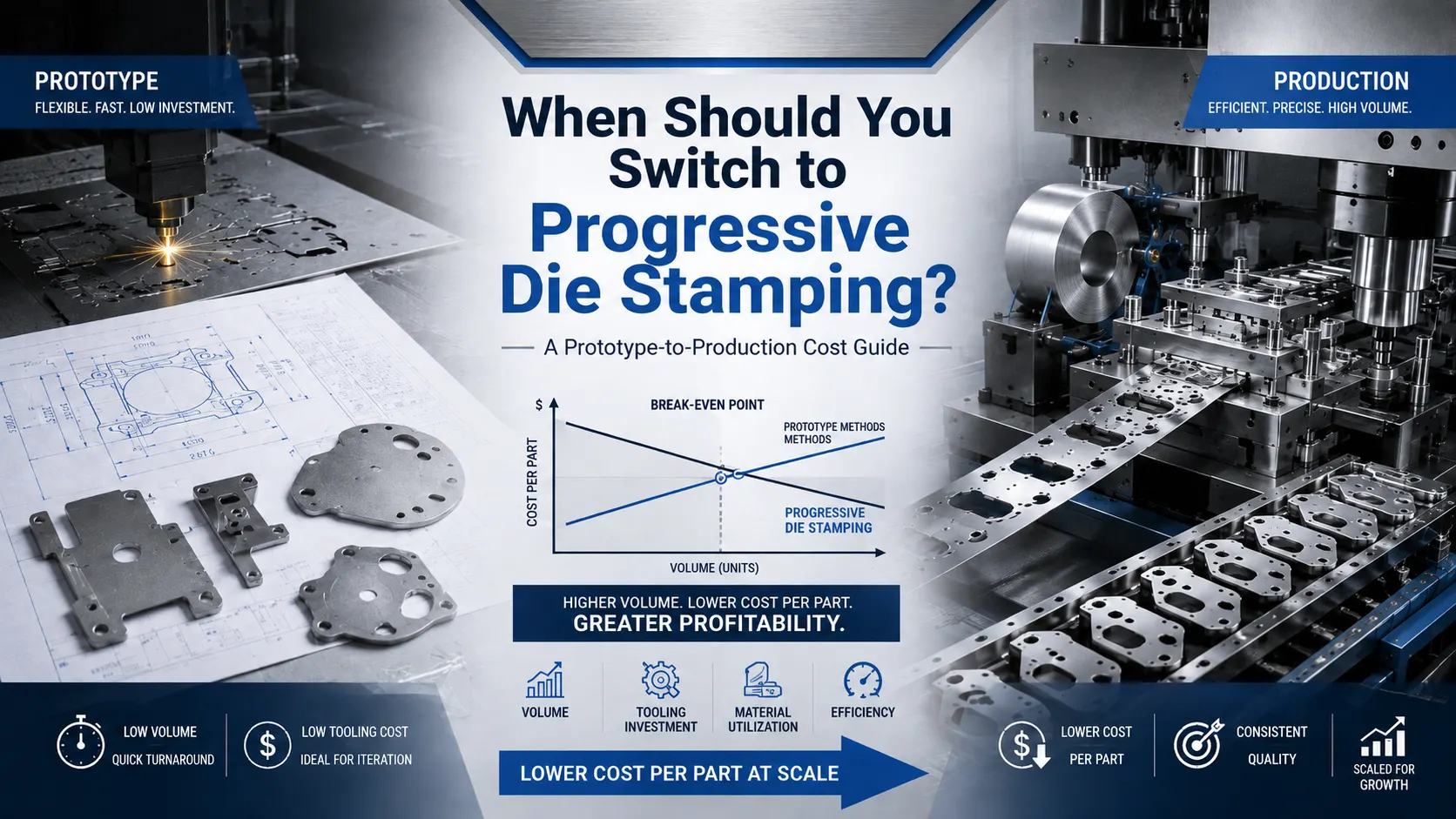
    CNC加工と金属プレス加工のどちらを選ぶかは、単に単価の問題ではありません。重要なのは、部品の形状、設計の成熟度、予想される生産量、そして生涯需要が、専用のプレス金型を正当化するかどうかです。CNC加工は、試作品、需要が不確実なもの、棒状またはブロック状の形状、そして変更の可能性が高い部品には、多くの場合より安全です。安定した板金設計が長期間繰り返され、金型投資を完成部品全体に分散できる場合は、金属プレス加工がより魅力的になります。場合によっては、最もリスクの低い解決策は、基本形状をプレス加工し、重要な部分のみを機械加工するというハイブリッド方式です。

    CNC加工、金属プレス加工、それともハイブリッド加工?

    プロジェクトの状況 CNC加工 金属プレス加工 ハイブリッドルート
    デザイン変更の可能性あり しっかりとしたフィット感 高い工具リスク 部分的な設計凍結後に可能
    需要は不確実 しっかりとしたフィット感 正当化するのが難しい 橋梁製造に役立つ
    安定した繰り返しボリューム ライフサイクルコストの見直し 有力な候補者 有力な候補者
    ソリッドバーまたはブロック形状 しっかりとしたフィット感 通常は不適切 限定
    シートまたはコイルの形状 可能 有力な候補者 有力な候補者
    精密な穴、ねじ山、または基準面 しっかりとしたフィット感 二次的な作業が必要になる場合があります 多くの場合実用的

    生産量や設計が不確実な場合は、CNC加工を継続する

    CNC加工は通常、プロジェクトが機能、適合性、要求、または最終形状を検証している段階に適しています。専用の生産金型なしで修正を受け付け、板材、棒材、またはブロック材から複雑な形状を作成できます。これにより、 精密CNC加工サービス 試作品、試作生産、交換部品、および生産量がまだ金型償却を正当化する規模に達していないリピート注文に該当します。

    プログラミング、治具、材料歩留まり、バッチ価格、検査、および修正コストを確認してください。部品ごとに長いサイクルタイムが必要であったり、多くの原材料が除去される場合、機械加工は高額になる可能性があります。ただし、体積に関係なく、シートから形状を成形できない場合は、機械加工は妥当な価格となる可能性があります。

    形状、需要、設計が安定している時にプレス金型に投資する

    部品が平板から打ち抜き、穴あけ、曲げ加工、成形、または引き抜き加工が可能で、かつ変更される可能性が低い場合に、生産用金型は実用的になります。金型には初期費用がかかりますが、繰り返し生産を行うことで、その投資をプログラム全体に分散させることができます。材料の特性、公差、および予想される摩耗は、事業計画に影響を与えます。設計変更が遅れると、金型の大幅な再加工が必要になる場合があるため、金型リリース前に機能テストと図面承認を行う必要があります。

    承認する前に 精密金属プレス加工および金型製作サービス材料、厚み、成形可能性、重要寸法、二次加工、ライフサイクル数量、改訂状況などを網羅した製造可能性レビューを依頼してください。プレス加工が採算に合うことを証明する普遍的な生産基準はありません。

    重要な部分のみを加工する必要がある場合は、ハイブリッドプロセスを使用してください。

    これらの工程は必ずしも相反する選択肢ではありません。プレス加工されたブランク材で外形、曲げ加工、成形加工を行い、タッピング、リーマ加工、研削、フライス加工によって重要な接合部を完成させることもできます。

    この方法は、プレス加工部品が再現性のある位置決め基準を提供し、二次加工サイクルが短い場合に最も効果的です。成形歪みによって治具が不安定になる場合や、ほとんどの形状が依然として機械加工を必要とする場合は、あまり魅力的ではありません。 二次加工を施したプレス加工済みPCB端子台 その原理を実証しているのが、公開されている製造工程である。この工程では、精密なプレス加工、曲げ加工、ねじ切り加工、穴あけ加工、電気めっき加工を組み合わせている。


    精密プレス加工、曲げ加工、ねじ切り加工、穴あけ加工、および二次加工工程を経て製造されるPCB端子台

    プレス加工用金型が必ずしも費用対効果が高いとは限らない理由

    生涯需要、変化、および隠れた運用を考慮に入れる

    製品ライフサイクルが短い、顧客による改訂が頻繁である、あるいは需要が不確実であるといった状況では、金型投資を回収するのに十分な部品が消費されない可能性があります。楽観的な年間予測に頼るのではなく、ライフサイクル全体を通しての低、予想、高の各数量をモデル化してください。

    プレス加工部品の完成コストには、バリ取り、タッピング、機械加工、洗浄、メッキ、コーティング、検査、組み立て、梱包、工具メンテナンス、および必要に応じて修正費用を含める必要があります。見積書には、試作、サンプル検査、修正作業、研磨、スペアパーツ、保管、およびメンテナンス費用が含まれているかどうかを明記する必要があります。金型製作開始後の変更はコストと遅延の原因となるため、正式な金型リリースは重要な管理手段となります。

    プレス加工金型の損益分岐点を計算する方法

    完全に定義された2つの製造ルートを比較する。

    損益分岐点数量 = 工具投資額 ÷ (CNC加工完了時の単位コスト − プレス加工完了時の単位コスト)

    「完了」が重要です。CNC加工のコストには、材料費、セットアップ費、機械加工費、工具費、検査費、仕上げ費、梱包費が含まれます。プレス加工のコストには、金型設計費、試作費、プレス生産費、材料利用費、メンテナンス費、二次加工費、検査費、仕上げ費、梱包費が含まれます。

    プレス加工されたブランク材にCNC加工による穴あけやねじ切りが必要な場合は、プレス加工のみの価格ではなく、完成したハイブリッド部品の価格を使用してください。複数の生産量シナリオをテストしてください。単位コストの差が小さいと投資回収期間が長くなりますが、差が大きい場合は、金型製作をより早く行う方が正当化される可能性があります。

    すべての入札者に、同じ図面改訂版、材料、数量区分、検査範囲、仕上げ、梱包、および工具所有権の条件を提示するよう依頼してください。そうしないと、見積もり内容が異なる作業内容となる可能性があります。「どのくらいの生産量であればプレス金型を正当化できるか?」という問いに対する適切な答えは、業界全体の数値ではなく、プロジェクト固有の損益分岐点の範囲です。

    CNC加工された部品は金属プレス加工に適していますか?

    まず、その形状が板材またはコイル材から製造可能かどうかを判断します。プレス加工は平らな材料を切断・成形するのに対し、機械加工は固体ワークピースから材料を除去します。厚みのある部分、閉じた形状、または複雑な多平面形状は、直接変換できない場合があります。

    プレス加工可能なフィーチャと重要な機械加工フィーチャを分離する

    まずは基本形状から見ていきましょう。その機能では、一定の板厚が使用できるでしょうか?曲げ、絞り深さ、穴と端面の関係、スプリングバック、バリが発生しやすい表面などを確認してください。

    図面上の特徴を、プレス加工に適したもの、設計変更または公差変更後に加工可能なもの、そして機械加工が必要なものの3つのグループに分類します。精密な穴、深いねじ山、シール面、ベアリング位置、および基準面は、二次加工として残しておく場合があります。位置決め基準、機械加工代、および成形誤差が最終的なセットアップにどのように影響するかを確認します。プレス加工部品の高精度な穴や取付面には、二次CNC加工が一般的に使用されます。

    CNCプロトタイプからプレス加工による量産へ移行する方法

    CNCプロトタイプは機能性を検証するものの、必ずしもプレス加工の適性を保証するものではありません。その図面には、鋭角な形状、厚みのばらつき、あるいは成形ではなく機械加工を前提とした厳しい公差が含まれている場合があります。

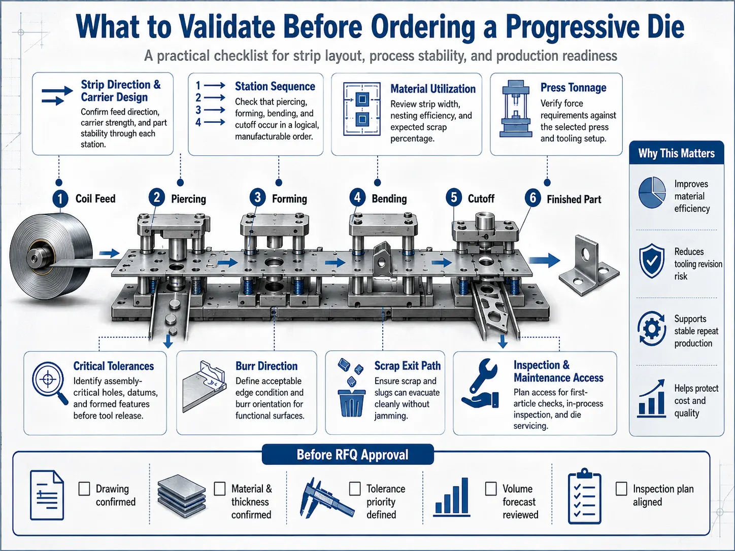
    要件を確定し、その後、DFMと初回製品承認を使用する

    金型製作前に、材料、厚み、接合部、重要寸法、仕上げ、図面の修正内容を確認してください。機能変更や顧客インターフェース変更が進行中のプロジェクトは、重大なリスクが解消されるまで、柔軟なプロセスを維持する必要があります。

    管理された移行は、プロトタイプの検証、プレス加工DFM、製造図面の改訂、金型設計、金型試作、サンプル検査、修正、初回品承認、試作、そして量産開始という順序で行われます。サンプルレビューでは、寸法だけでなく、バ​​リ、亀裂、しわ、スプリングバック、めっき状態、外観、組立性能なども評価対象とする必要があります。

    CNC加工からプレス加工までの見積依頼書に購入者が含めるべき内容

    正確な見積もりには、最新の2D図面とSTEPファイル、材料と形状、厚み、年間および耐用年数、現在の製造工程、重要な公差、仕上げ、二次加工、検査、梱包、および既知の変更点が必要です。

    また、工具の所有権、保管、メンテナンス、研磨、予備インサート、改造費用、譲渡権、およびプログラム終了時の取り扱いについても比較検討してください。金型価格が安い場合、設計変更や生産サポートが含まれていないと、後々コストがかさむ可能性があります。

    CNC加工からプレス加工への移行におけるサプライヤーの選定

    適格なサプライヤーは、両方のルートを評価する必要があります。金型が社内で製造されているか、試作チームと量産チームが責任を共有しているか、二次加工を調整できるか、そして初回生産品、改訂、金型摩耗、是正措置がどのように管理されているかを確認してください。

    浙江創凱機電科技有限公司(CK Metal Techとしても知られる)は、金型製作、金属プレス加工、CNC加工、表面処理、検査、組立を自社工場内で統合している。 精密金属加工の統合 事業範囲。確認済みの設備には、4軸CNC工作機械8台、高精度CNC旋盤18台、スイス型旋盤加工設備が含まれます。CK Metal Techは、順送金型、絞り加工型、複合加工型の金型も製造しており、IATF 16949認証を取得しています。これにより、フルCNC加工、フルプレス加工、ハイブリッド加工の工程レビューに対応可能です。

    結論

    プレス加工金型は、部品が本当にプレス加工可能で、設計が安定しており、金型、メンテナンス、検証、二次加工、および改訂リスクにかかる費用を上回る生涯コスト削減効果が得られる場合に有効です。CNC加工は、試作品、設計変更、ソリッド形状、および精密な形状の加工に依然として有効です。基本形状はプレス加工で可能だが、機能的なインターフェース部分には機械加工が必要な場合、ハイブリッドプロセスが最もバランスの取れた方法となる可能性があります。

    プロジェクトレビューのために、最新の図面、STEPファイル、材料、目標数量、プログラム寿命、重要寸法、二次加工、および品質要件を準備してください。これらの詳細により、CK Metal Techは CNC加工からプレス加工までのDFMレビューを依頼する また、すぐに工具を導入する必要なく、実現可能なルートを比較検討できる。

    よくある質問

    どのくらいの生産量であれば、金属プレス加工はCNC加工よりも安価になるのでしょうか?

    普遍的な数量はありません。損益分岐点は、実際の工具投資額と、メンテナンス、二次加工、仕上げ、検査、設計変更リスクを含めた、完成したCNC加工とプレス加工の単位コストの差額から計算してください。

    CNC加工された部品を、そのまま金属プレス加工に変換することは可能ですか?

    場合によっては、しかし通常はDFM(設計製造性)なしでは不可能です。ソリッドセクション、可変厚み、深い形状、または厳しい公差などは、金型製作開始前に設計変更が必要になる場合があります。

    プレス加工された部品は、今でもCNC加工が必要ですか?

    必要になる場合があります。ねじ山、精密な穴、ベアリング嵌め合い、シール面、基準面、またはタイトな取り付け部などは、二次加工、穴あけ、ねじ切り、リーマ加工、または研削が必要になることがあります。

    プレス加工用金型への投資が採算に見合うかどうか、購入者はどのように判断すればよいのでしょうか?

    印刷の可否を確認した上で、需要が低い場合、予想される場合、高い場合のそれぞれのシナリオにおけるライフサイクルコストを比較してください。設計が確定しており、隠れた工程も両方の見積もりに含まれている場合、比較の妥当性は高まります。

    プレス金型メーカーを選ぶ際に確認すべき点は何ですか?

    社内での工具設計、DFM(製造性設計)サポート、試作、初回品手順、改訂管理、二次加工、検査、工具保守、所有権条件、および生産品質管理について確認する。

    WhatsApp
    メール
    連絡先