장카이

에이 에이 N

로딩 중


스탬핑 및 툴링

문의하기
벡터

자주 묻는 질문

사진 문의하기

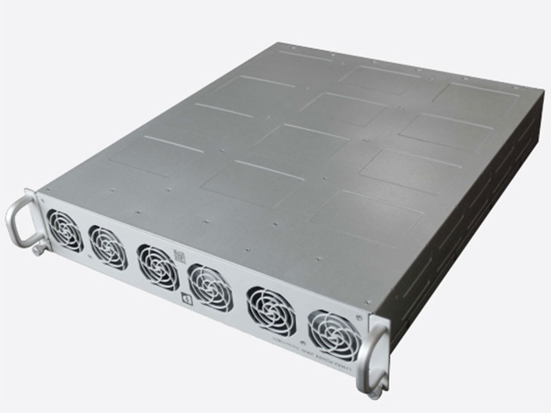
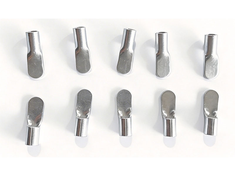
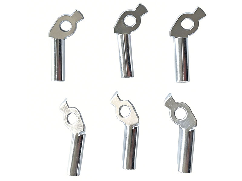
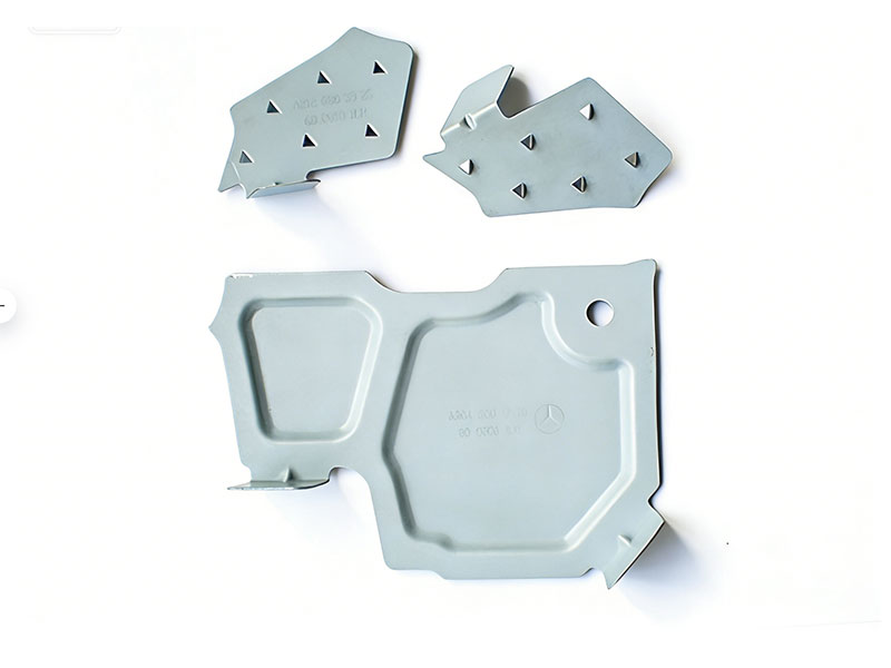
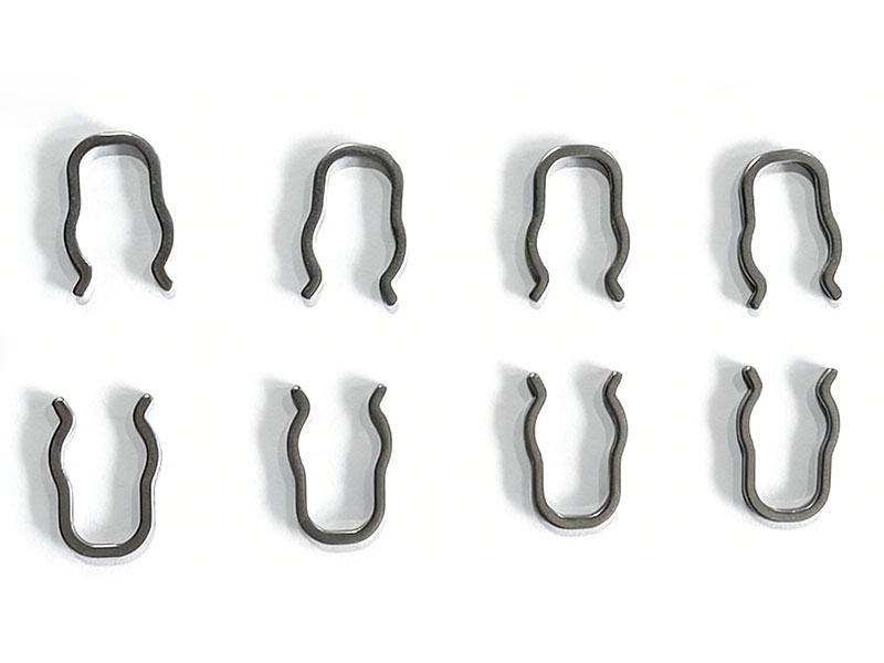
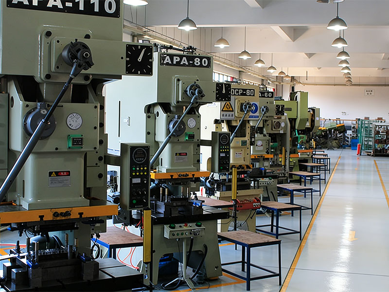
정밀 스탬핑 부품은 펀칭 공정에서 단일 스테이션 클램핑 및 위치 지정을 통해 고정밀 금형으로 제조됩니다. 스탬핑 기계에서 가공물의 치수 정확도와 위치 공차 요구 사항이 엄격하기 때문에 금형 연마, 열처리, 표면 처리 및 조립을 포함한 정밀한 후가공 공정이 필수적입니다. 이러한 부품은 일반적으로 소량 배치 또는 개별 부품으로 생산되므로 생산량이 비교적 적고, 결과적으로 기계에 대한 요구 사항이 덜 엄격합니다. 스탬핑 공정에서 재료는 금형의 틈새를 통해 다이 캐비티로 흘러 들어갑니다. 압력 하에서 재료는 분리되거나 소성 변형되어 원하는 모양과 구조를 얻습니다. 압력 해제 후 제어된 성형 공정을 통해 완제품이 만들어집니다. 이러한 특성 때문에 스탬핑은 고전적인 냉간 인발 기술이라고 할 수 있습니다. 실제 생산에서 제품 품질을 보장하고 효율성을 높이며 폐기물을 줄이고 에너지를 절약하기 위해 제조업체는 일반적으로 다음과 같은 전략적 조치를 시행합니다. 1. 적절한 금형 사용 2. 합리적인 원자재 선택 3. 합리적인 공정 규정 수립 4. 작업자의 기술 교육 향상 5. 기계 자동화를 향상시킵니다. 6. 작업 환경을 개선합니다. 스탬핑 부품 ​​제조의 특징: (1) 재료 이용률이 높습니다. (2) 비교적 얇은 판재로 복잡한 제품을 제작할 수 있습니다. (3) 구조 기둥을 포함하는 다양한 구조로 제작할 수 있습니다. (4) 두꺼운 벽의 중공 구조를 만들 수 있습니다. (5) 넓은 면적의 판재로 제작할 수 있습니다. (6) 기계화가 용이합니다. (7) 기계화 및 자동화 완료가 용이합니다. (8) 시스템 구축이 용이합니다.

정밀 기계 부품 제조는 일반적으로 매우 높은 정밀도를 요구하는 정밀 기계용 부품 가공을 포함합니다. 따라서 정밀 기계 부품 가공에 필요한 특정 재료 요구 사항과 일반적인 기술을 이해하는 것 외에도 전체 생산 공정을 아는 것이 중요합니다. 아래에서는 정밀 기계 부품 제조의 5단계를 간략하게 설명합니다. 1. 황삭 가공 생산성 향상이 핵심 목표입니다. 각 표면의 가공 능력을 대부분 제거하고 기준면을 만듭니다. 2. 준가공 가공 황삭 가공 후 발생할 수 있는 결함을 제거하고 1차 및 2차 표면 가공을 동시에 수행합니다. 정삭 가공을 위한 준비를 용이하게 하고 적절한 정삭 능력을 확보하기 위해 일정한 가공 정밀도를 달성해야 합니다. 3. 정삭 가공 정삭 가공 단계에서는 준가공 가공에서 남은 가공 능력을 제거하기 위해 일반적으로 많은 절삭량, 적은 이송량 및 절삭 깊이를 사용하여 정밀 기계 부품의 표면이 도면의 기술 표준을 충족하도록 합니다. 4. 연마 주로 표면 거칠기를 줄이거나 가공된 표면을 강화하는 데 사용되며, 특히 표면 거칠기 요구 사항이 높은 표면 가공에 주로 사용됩니다. 5. 초정밀 가공 일반적으로 정밀 드릴링, 정밀 미러 커팅, 정밀 연삭 및 연마를 통해 공작물의 가공 정밀도는 0.1~0.01μm이고 표면 거칠기 값 ra는 0.001μm 이하입니다. 기계 부품의 5단계 정밀 가공 공정은 황삭에서 정삭으로 진행되며, 정밀도가 점진적으로 향상됩니다. 이러한 체계적인 접근 방식을 통해 부품은 고객 요구 사항에 따른 사양을 충족합니다. 윤투오 머시닝은 정밀 기계 부품 제조 전문 기업입니다. 고객이 제공한 도면과 재료를 기반으로 맞춤형 서비스를 제공하여 고객의 모든 기대를 충족하는 정밀 엔지니어링 부품을 제공합니다.

무료로 보내주세요
메시지


    최근의
    블로그 게시글

    How to Control Runout in Long Shaft Machining: Setup, Grinding, and Inspection for Parts Up to 4 Meters

    07
    8월


    How to Control Runout in Long Shaft Machining Setup, Grinding, and Inspection for Parts Up to 4 Meters

    Long shaft machining becomes difficult when a part passes diameter inspection but still shows excessive runout, bow, taper, vibration, or assembly misalignment. The cause may begin in the raw material, appear during stock removal, develop after heat treatment, or result from an inspection setup that does not reproduce the drawing datum. For shafts approaching four meters, material condition, workholding, machining sequence, grinding, inspection, and packaging must form one controlled process.

    Long Shaft Machining Runout: Diagnose the Pattern First

    Runout is commonly checked by rotating the shaft through 360 degrees and comparing the indicator’s maximum and minimum readings at a specified position. The result is meaningful only when the datum, support method, gauge position, and permitted value are defined.

    Observed condition Check first Next action
    Runout is concentrated near one end Center holes, chucking, tailstock, datum transfer Verify the setup axis
    Maximum bow appears near the middle Support spacing, stock straightness, cutting force Review support and roughing
    Diameter changes along the shaft Tailstock alignment, tool wear, thermal drift Separate geometric and thermal error
    Runout increases after heat treatment Residual stress, support, remaining allowance Recheck straightness before finishing
    Inspection reports disagree Datum, support points, orientation, gauge position Agree on one method

    This identifies whether the next review should focus on material, setup, grinding, or measurement.

    Why Long Shafts Develop Runout, Taper, and Straightness Errors

    Material Straightness, Residual Stress, and Heat-Treatment Distortion

    A long bar may contain initial bow or uneven residual stress. Heavy material removal can release that stress and move a shaft that appeared straight during roughing. Thin sections, keyways, and large diameter changes increase the risk.

    For parts requiring substantial stock removal or heat treatment, a staged route may be safer than machining directly to final size. Rough turning establishes the geometry, followed by a stability or heat-treatment step when specified, another straightness check, and finish machining. Remaining allowance should be distributed so final turning or grinding does not need to correct most of the error from one side.

    The RFQ should identify material grade, supply condition, heat treatment, hardness, and incoming straightness requirements.

    Cutting Force, Unsupported Length, Clamping, and Heat

    A slender shaft deflects under radial cutting force. As unsupported length increases, the tool may push the workpiece away, causing taper, barrel shape, chatter, or inconsistent diameter. Excessive chuck, tailstock, or steady-rest pressure can also bend the shaft before cutting.

    Lower cutting force, short tool overhang, staged passes, controlled support, and temperature management reduce risk. A strategy that works on a rigid section may fail at the smallest diameter. Buyers should ask how the supplier will support that section, manage tool wear and thermal growth, and perform in-process checks.

    Choosing the Right Setup for Long Shaft Turning

    The setup should reflect shaft length, diameter, weight, material, critical datums, and permitted runout. Buyers can review CK Metal Tech’s long shaft CNC machining and grinding capabilities before submitting a drawing.

    Between-Centers Turning and Tailstock Alignment

    Turning between centers can preserve one rotational axis through several operations when center holes remain available as process datums. It is useful when multiple journals must relate to the same axis, although end geometry, weight, or feature access may require another setup.

    Center holes must be prepared and protected because inconsistent seating transfers into runout. Tailstock alignment and thrust also matter: insufficient support permits movement, while excessive force may bow a slender shaft. The supplier should check initial indicator readings, explain how the part will be reloaded, and confirm whether center holes are temporary process features or drawing-controlled features.

    Steady Rest vs. Follow Rest

    A steady rest supports the shaft at a fixed position; a follow rest moves with the cutting tool. The correct choice depends on where the unsupported span develops.

    Official machine guidance describes steady rests as support for long or narrow shafts and instructs operators to adjust rollers without causing workpiece deflection. It also recommends rotating the part and checking it with an indicator after adjustment.

    Rollers that are too loose provide little control; rollers that are too tight can create friction, marks, heat, or artificial bending. The supplier should identify support locations and explain how alignment will be rechecked after repositioning.

    Machining Sequence for Controlling Long-Shaft Runout

    Rough Turning, Stability Review, and Finish Turning

    A sound process separates heavy stock removal from final geometry control. Rough turning establishes the shape and reveals how the blank responds as material is removed. The shaft can then be checked for bow and datum movement before heat treatment, semi-finishing, or grinding.

    A typical route is:

    Material review → datum preparation → rough turning → stability or heat-treatment step → straightness review → semi-finishing → finish turning or grinding → final inspection.

    The exact route depends on material, geometry, hardness, and drawing requirements. Repeated chucking should be minimized or controlled through consistent center holes, journals, or other process datums.

    When Grinding Is Required—and When Turning Is Enough

    Grinding may suit hardened journals, bearing fits, wear surfaces, or requirements involving surface condition, roundness, cylindricity, and relationships between diameters. It should not be added automatically. If finish turning meets the drawing, another setup may add cost and datum-transfer risk.


    Precision shaft components manufactured with CNC turning and grinding processes for long shaft machining applications

    For ground shafts, confirm the grinding datum, support method, allowance, heat-treatment sequence, and equipment range. CK Metal Tech’s 정밀 가공된 샤프트 부품 및 연삭 작업 use a published route combining precision turning, grinding, and quenching for custom alloy-steel or stainless-steel designs.

    This product does not establish a four-meter grinding range. Maximum length, diameter, weight, and geometry must be verified for each drawing.

    How to Inspect Runout and Straightness on a Long Shaft

    Define the Datum Axis Before Selecting the Gauge

    Circular runout, total runout, straightness, roundness, and coaxial relationships describe different conditions. A shaft may meet diameter tolerance while failing rotational function. The drawing should identify the functional datum axis and the characteristic that affects assembly.

    The datum may come from center holes, two bearing journals, or another functional feature. Measuring one section does not prove the complete shaft meets total runout or straightness requirements. Reports should state the datum, support method, gauge positions, orientation, rotation method, and result.

    Control Gravity Sag and Measurement Support

    A long slender shaft can sag under its own weight during horizontal inspection. Between-centers measurement, rollers, V-blocks, and coordinate measurement systems may produce different readings if support positions and datums are not correlated.

    Inspection equipment must match the workpiece envelope, weight, access, and required uncertainty. A CMM may suit some features, but it should not be assumed that every machine can accommodate a complete four-meter shaft. Supplier and buyer should agree on support spacing, orientation, rotation method, and measurement correlation.

    CK Metal Tech has CMM, 2.5D measurement, metallographic, and hardness-testing resources, but the method for a full-length four-meter shaft must be confirmed against the equipment range.

    Troubleshooting Long-Shaft Machining Defects

    Runout near one end points first to the chuck, center hole, tailstock, or datum transfer. Maximum bow near the middle suggests stock straightness, support spacing, cutting force, or stress release. Gradual taper calls for checks of alignment, tool wear, machine geometry, and temperature. Periodic chatter may indicate poor rigidity, unsuitable speed, excessive tool overhang, or unstable rest contact.

    If runout increases after heat treatment, verify straightness before removing final allowance. If grinding introduces new error, review grinding heat, support pressure, wheel condition, and datum correlation. Rework should not begin until the cause and remaining allowance are understood.

    RFQ Checklist for Long Shafts Up to 4 Meters

    Drawing, Material, and Application Data

    Provide the current 2D drawing and 3D model, total and effective machining lengths, maximum and minimum diameters, estimated weight, material grade and condition, center holes, functional datums, and all stepped, threaded, tapered, keyed, or drilled features.

    State circular runout, total runout, straightness, surface requirements, heat treatment, hardness, grinding scope, and inspection records. Application details such as speed, load, mating components, and environment help identify critical features. Include quantities and any photographs or reports from an existing defect.

    Capacity, Inspection, and Packaging Questions

    Ask the supplier to confirm usable between-centers length, maximum diameter and weight, lifting method, tailstock and rest configuration, and which turning, heat treatment, grinding, and inspection stages are internal or outsourced. Confirm grinding range rather than assuming it matches turning capacity.

    The quotation should identify datum simulation, inspection supports, sample and production setups, and packaging. A shaft that passes inspection can still bend if supported incorrectly during storage or transport.

    How to Choose a Long Shaft Machining Supplier

    Evaluate the Complete Manufacturing Route

    A suitable supplier should explain how material review, datum preparation, roughing, support, heat treatment, finishing, grinding, inspection, and packaging connect. The review should identify where straightness is checked, how setups are repeated, which features establish the final axis, and what happens if the shaft moves after heat treatment.

    Buyers should confirm whether first articles and production parts use the same route, which records are available, and how abnormal results are handled. Confirming machine length without discussing weight, support, grinding, and inspection is not a complete feasibility review.

    Relevant CK Metal Tech Capabilities

    Zhejiang Chuangkai Mechanical and Electrical Technology Co., Ltd. connects machining with related processes through its 통합 정밀 금속 제조 역량. Buyers can also review 저장촹카이 기계전기기술유한공사에 대하여 when evaluating the supplier.

    Confirmed resources include 18 precision CNC lathes, turning capacity for workpieces up to approximately four meters, internal and external cylindrical grinding, centerless grinding, thread rolling, tapping, and drilling. CK Metal Tech also holds IATF 16949 certification, while its website presents machining, stamping, sheet-metal fabrication, surface treatment, and assembly as connected services.

    Maximum diameter, weight, grinding length, support arrangement, and achievable runout or straightness must still be verified for each project.

    결론

    Controlling runout in long shaft machining requires more than a long-bed lathe. Material condition, datums, support pressure, cutting force, heat treatment, grinding, inspection, and transport must form one traceable route. The objective is to meet the drawing under an agreed measurement method, not to promise “zero runout.”

    For a process review, submit the drawing, material, length, diameters, estimated weight, runout and straightness requirements, heat treatment, grinding scope, quantity, application, and any defect photographs or reports. Buyers can request a long shaft machining review CK 메탈 테크에서 제공합니다.

    자주 묻는 질문

    How can runout be reduced when machining a long shaft?

    Check raw-material straightness, datums, chuck and tailstock alignment, support location, cutting force, tool condition, and temperature. Separate roughing from finishing when stress release is likely, then inspect with the agreed datum and support method.

    When is a steady rest required for long shaft turning?

    A steady rest may be needed when the unsupported span permits deflection, vibration, or unstable size. The decision depends on diameter, length, weight, material, cutting force, geometry, and tolerance.

    Should a long shaft be ground after CNC turning?

    Grinding is appropriate when hardness, bearing fits, wear surfaces, roundness, cylindricity, or surface requirements cannot be met reliably by turning. It may be unnecessary when finish turning satisfies the drawing.

    How is total runout measured on a four-meter shaft?

    Define the datum axis, support arrangement, rotation method, and measurement locations. The method must consider gravity sag, equipment range, and correlation between supplier and customer inspection.

    What information is needed for a long shaft machining quote?

    Provide drawings, material condition, length, diameters, weight, datums, runout and straightness tolerances, surface requirements, heat treatment, grinding, features, quantities, application, inspection records, and packaging expectations.

    3-Axis vs 4-Axis CNC Machining: When Does a Rotary Axis Reduce Setups and Datum Error?

    06
    8월


    3-Axis vs 4-Axis CNC Machining When Does a Rotary Axis Reduce Setups and Datum Error

    Choosing between 3-axis and 4-axis CNC machining should begin with the drawing, not the machine list. A rotary axis can expose several sides of a component without manual flipping, which may reduce fixture changes, repeated probing, and datum transfer. It does not automatically make every part more accurate or less expensive. The correct route depends on feature direction, tool access, cross-face tolerances, workholding, quantity, and inspection.

    3-Axis or 4-Axis CNC Machining? Quick Decision Guide

    Map every machined feature by direction, then identify which features must remain related to the same functional datum.

    Decision factor 3-axis machining often fits 4-axis machining often fits
    Feature direction One or two accessible directions Three or more sides or radial directions
    Cross-face relationships Moderate or fixture-repeatable Tight relationships around a common datum
    Rotary features Limited and easy to re-fixture Radial holes, circular slots, angular patterns
    Quantity Prototype, low volume, changing design Stable pilot or repeat production
    Setup plan One or two direct setups Several 3-axis setups can be consolidated

    The process should be reviewed against the actual part, not specified only as “4-axis required.” Buyers can examine CK Metal Tech’s precision CNC machining capabilities when a drawing needs process review.

    Choose 3-Axis Machining for Accessible, Single-Direction Features

    Three-axis machining remains practical for plates, brackets, flanges, and simpler housings whose critical features are accessible from the top or one additional flipped orientation. A qualified flip fixture and probing can make a second setup repeatable enough for many drawings.

    It is often more economical for prototypes, low quantities, or changing designs. Buyers should still ask how many times the part will be clamped, which datum is used, and where cross-face dimensions will be inspected.

    Choose 4-Axis Machining for Multi-Sided or Rotary Features

    Four-axis machining becomes more relevant when holes, slots, flats, or mounting faces are distributed around a part, or when cylindrical features require controlled angular spacing. Rotating the workpiece can give the tool access to several directions while preserving one primary clamping relationship.

    Autodesk identifies multi-sided, cylindrical, and wrapped geometry as common 4-axis applications and notes that less re-clamping can reduce cumulative setup error. Undercuts or compound angles may still require 5-axis machining or another process.

    How Multiple Setups Create Datum Shift and Positional Error

    Re-Clamping, Re-Zeroing, and Fixture Stack-Up

    Every new setup introduces variables such as debris under a locator, fixture error, clamping deformation, probe variation, work offsets, and inconsistent seating. Their combined effect can appear in features produced from different setups.

    A part may pass individual checks yet fail cross-face position, perpendicularity, or center distance. Multiple setups remain acceptable when tolerance and fixture repeatability support them. Clear datums, probing, and first-article checks reduce risk.

    Why 4-Axis Machining Reduces—but Does Not Eliminate—Error

    Keeping the part clamped while it indexes removes some manual handling and repeated zero-setting. Autodesk describes this as a reason 4-axis machining can reduce misalignment and cumulative tolerance error.

    The rotary setup still has an error chain. The workpiece must match the rotation center; the fixture must resist eccentric loading; and indexing, offsets, heat, and clamping must be controlled. Autodesk support identifies an incorrect work-coordinate position relative to the rotary center as a cause of wrong 4-axis output.

    Part Geometry and GD&T Requirements That Drive Axis Selection

    Multi-Sided Holes, Slots, Flats, and Mounting Features

    Strong 4-axis candidates often contain features on adjacent or opposite faces that share a critical relationship. Examples include mounting holes around a housing, flats indexed at specified angles, or several faces referenced to one bore.

    The drawing should identify which features control assembly. Position, perpendicularity, parallelism, and profile across faces may justify one rotary setup. If these relationships are loose, a 3-axis flip fixture may be sufficient. Buyers should mark cross-face critical dimensions and ask how each will be produced and measured.

    Cylindrical, Wrapped, and Repeating Angular Features

    Radial holes, circumferential grooves, engraving, and angular patterns are natural rotary-axis applications. Indexed machining positions the workpiece at defined angles; wrapped or simultaneous motion may be needed for a continuous path around a cylinder.


    Four-axis CNC machined motor housing with annular cooling grooves for multi-sided machining applications

    A relevant example is a four-axis CNC-machined motor housing made from high-strength aluminum alloy. Its published annular cooling grooves and mounting holes illustrate why rotary access may suit cylindrical and installation features. The page does not provide setup savings or tolerance comparisons.

    Indexed 3+1 vs Simultaneous 4-Axis Machining

    When Indexed 4-Axis Machining Is Sufficient

    In indexed, or 3+1, machining, the rotary axis moves the part to a fixed angle and stops. Standard 3-axis toolpaths then machine that orientation. Autodesk separates this method from continuous rotary cutting.

    It suits bolt patterns, radial holes, flats, pockets, and mounting features at known angles. It is generally easier to program and inspect than simultaneous motion. A quote should state indexed positions, feature groups, support, and remaining setups.

    When Simultaneous Rotary Motion Is Required

    Simultaneous 4-axis machining moves the rotary axis while cutting. It may fit helical grooves, wrapped contours, or free-form cylindrical surfaces that cannot be produced efficiently by fixed indexing. Autodesk notes that these workflows require rotary-orientation control, clearance planning, and collision avoidance.

    The machine configuration, CAM strategy, postprocessor, rotary direction, and collision model must agree. Not every “4-axis” machine supports the same continuous strategies. Buyers should specify the required geometry rather than demand simultaneous motion by default.

    3-Axis vs 4-Axis CNC Machining Cost

    Compare Completed-Part Cost, Not Machine Hourly Rate

    A 4-axis machine may have a higher hourly rate, but the completed part may cost less if it replaces fixtures, setups, transfers, and intermediate inspection. A simple component may cost more because of added programming, alignment, and workholding.

    A fair comparison includes programming, fixtures, setup labor, cycle time, tooling, inspection, first-article approval, and rework risk. Separate one-time charges from recurring unit costs, and require the same finished scope.

    Prototype, Pilot, and Repeat Production Decisions

    A prototype may be produced efficiently in two 3-axis setups while the design is changing. After interfaces and quantities stabilize, a rotary fixture may become worthwhile for pilot or repeat production. The break point depends on fixture cost, setup time, inspection effort, geometry, and lifetime quantity.

    Changing the route can alter datum flow, tool marks, burr location, and measurement. If prototype and production methods differ, critical characteristics need renewed pilot-run validation.

    Common 4-Axis Machining Risks and How to Prevent Them

    Rotary Centerline, Workholding, and Orientation Errors

    If the programmed coordinate system does not match the actual rotary centerline, features can shift as the part turns. Fixture eccentricity may create changing tool engagement, vibration, and angular error. A reversed rotary direction or incorrect zero can mirror or misplace wrapped features.

    Controls include probing the centerline, checking indicator readings, simulating the machine and fixture, verifying the postprocessor, and inspecting a first article at several angular positions.

    Tool Access, Collision, Rigidity, and Part Deformation

    Rotating the part changes the collision environment. A tool, holder, spindle, chuck, fixture, or tailstock that clears at zero degrees may interfere at another angle. Long tools may reduce rigidity and offset the benefit of fewer setups.

    Thin-wall housings and long or eccentric parts can deform under rotary clamping. DFM should review clamping zones, support, tool reach, clearance, and material-removal sequence. Some features may remain safer as a separate 3-axis operation.

    RFQ Checklist for a 3-Axis vs 4-Axis Process Review

    Drawing, Datum, and Application Information

    Provide the current 2D drawing and STEP file, material and condition, datum system, cross-face positional tolerances, angular features, cylindrical surfaces, surface requirements, and the features that control assembly. Include prototype quantity, annual demand, inspection documents, and packaging needs.

    If an existing route is failing, attach its setup description, inspection report, and photographs of the nonconforming feature.

    Setup, Fixture, and Inspection Questions

    Ask each supplier to state:

    • The proposed number of setups
    • Whether the route is 3-axis, indexed 3+1, wrapped, or simultaneous 4-axis
    • Which features remain in one clamping
    • The rotary-axis direction and workholding concept
    • Whether auxiliary support is needed
    • How cross-face GD&T will be inspected
    • Whether samples and production use the same route
    • Which fixture and first-article charges are one-time costs

    How to Choose a 3-Axis and 4-Axis CNC Machining Supplier

    Verify the Process Plan, Not Only the Machine List

    A machine list does not show whether a supplier can select the correct route. A useful review identifies feature directions, datum flow, tool access, fixture risk, and inspection before quotation.

    Ask for a simplified setup map and the reason behind the axis selection. The supplier should recommend 3-axis machining when it is more direct and 4-axis machining when reduced handling creates an advantage. Confirm rotary-centerline and first-article controls.

    Relevant CK Metal Tech Capabilities

    Zhejiang Chuangkai Mechanical and Electrical Technology Co., Ltd., also known as CK Metal Tech, supports drawing-based projects through its 통합 정밀 금속 제조 역량. Confirmed resources include eight 4-axis CNC machines, four CNC milling machines, and 4-axis capacity for larger workpieces up to approximately 1.8 meters, subject to geometry, diameter, weight, fixture, and tool-access requirements.

    The company also has CMM and 2.5D inspection resources and holds IATF 16949 certification. CK Metal Tech’s machining scope includes milling, turning, grinding, drilling, and related operations. Specific rotary mode, work envelope, positional capability, and inspection method should be verified against each drawing.

    결론

    The decision between 3-axis and 4-axis CNC machining should follow three steps: map the required machining directions, identify cross-face dimensions that depend on a common datum, and compare complete setup, fixture, programming, and inspection cost. A rotary axis can reduce re-clamping risk, but only when the centerline, workholding, program, and inspection plan are controlled.

    Buyers can request a 3-axis vs 4-axis process review by submitting the drawing, STEP file, material, datum system, cross-face tolerances, circular features, quantity, and any existing setup or inspection report.

    자주 묻는 질문

    Does 4-axis CNC machining always improve accuracy?

    No. It can reduce manual re-clamping and datum transfer, but accuracy still depends on the rotary centerline, fixture, machine condition, work offsets, toolpath, heat, and inspection method.

    When is 3-axis machining more cost-effective?

    It is often more economical when features are accessible from one or two directions, quantities are low, the design is changing, and cross-face tolerances can be controlled with a direct fixture.

    What is the difference between 3+1 and simultaneous 4-axis machining?

    In 3+1 machining, the rotary axis positions the part and remains stationary during cutting. In simultaneous machining, the rotary axis moves continuously while the tool follows the programmed path.

    Can a 3-axis machine produce multi-sided parts?

    Yes. The part can be flipped or moved to another fixture. Suitability depends on setup count, fixture repeatability, cross-face tolerances, quantity, and datum-transfer risk.

    What information is needed for a 4-axis CNC machining quote?

    Provide drawings, a STEP file, material, datums, cross-face GD&T, radial or circular features, surface requirements, quantities, application details, and inspection expectations.

    스위스 머시닝 vs CNC 터닝: 작은 샤프트, 핀 및 가는 부품에 적합한 방식 선택 방법

    31
    7월

    스위스 머시닝과 CNC 터닝, 소형 샤프트, 핀 및 가는 부품 가공에 적합한 방법


    도면에 작은 직경, 긴 무지지 구간, 엄격한 런아웃 요구 사항 또는 2차 형상이 포함된 경우 스위스 머시닝과 기존 CNC 선삭 중 어떤 방식을 선택할지 결정하기 어려워집니다. 어떤 방식을 선택할지는 지지대 사용 여부, 절삭 길이, 소재 상태, 형상 복잡성, 공차 및 수량에 따라 달라집니다. 이 가이드는 엔지니어와 구매팀이 고정된 규칙에 의존하지 않고 샤프트, 핀, 슬리브, 커넥터 및 기타 가늘고 긴 부품을 평가하는 데 도움을 줍니다.

    스위스 머시닝 또는 CNC 터닝? 빠른 선택 가이드

    첫 번째 결정은 스위스식 기계가 더 정확하다는 가정이 아니라 기하학적 구조와 공정 위험을 고려하여 내려야 합니다. 구매자는 CK Metal Tech의 자료를 검토할 수 있습니다. 정밀 CNC 선삭 및 스위스 머시닝 기능 두 경로 모두 평가가 필요할 때.

    프로젝트 조건 스위스식 가공은 종종 적합합니다. 일반적인 CNC 선삭이 적합한 경우가 많습니다.
    지름은 작고 단면은 길고 가늘다 지지대는 절단면 가까이에 유지될 수 있습니다. 공작물 고정 및 절삭 전략으로 편향을 제어할 수 있다면 가능합니다.
    짧고, 견고하고, 간단한 부품 불필요한 설정이 추가될 수 있습니다. 종종 더 직접적인 경로
    가로 구멍, 평면, 홈 또는 후면 가공 기계가 여러 작업을 결합할 때 유용합니다. 부업이 경제적인 경우 실용적입니다.
    거래량이 적거나 불확실함 설정 및 기능에 따라 다릅니다. 정당화하기가 더 쉬운 경우가 많습니다.
    안정적인 반복 생산 작업 간 처리 과정을 줄일 수 있습니다. 더 간단한 형상에 경쟁력이 있음
    가변봉 직진도 또는 직경 스톡은 가이드 부싱에 적합해야 합니다. 작업 고정 방식에 따라 민감도가 떨어질 수 있습니다.

    소구경, 슬림형, 다기능 부품에는 스위스 머시닝을 선택하십시오.

    스위스 머시닝은 공구가 주 클램핑 지점에서 멀어질 때 부품이 휘거나 진동하는 경우에 일반적으로 고려됩니다. 가이드 부싱 작동 방식에서는 헤드스톡이 가이드를 통해 재료를 이송하는 동안 바가 절삭 영역 가까이에서 지지됩니다. 이는 절삭 중 지지되지 않는 길이를 줄여주므로 긴 정밀 핀, 좁은 계단형 샤프트 및 섬세한 부품 가공에 적합합니다.

    선삭, 횡방향 드릴링, 밀링, 나사 가공 또는 후가공 작업을 조합하여 수행할 수 있다는 점에서도 유용합니다. 구매자는 실제 기계 구성을 확인해야 합니다. 스위스형 선반은 가이드 부싱을 사용하거나 사용하지 않고 작동할 수 있으며, 라이브 툴링, 서브 스핀들 기능 및 사용 가능한 봉 크기도 다양합니다. 공개된 사양에 따르면 변환 가능한 스위스형 선반은 가이드 부싱 방식과 척 방식 모두를 지원할 수 있습니다.

    짧거나 크거나 구조가 간단한 부품에는 기존 CNC 선삭 방식을 선택하십시오.

    기존의 CNC 선삭 가공은 강성이 높은 부품, 단순한 외형, 큰 직경, 소량 생산 또는 도면 변경 가능성이 있는 경우에 여전히 실용적입니다. 하지만 직경이 하나이고 기본적인 나사산이 있는 짧은 핀의 경우 스위스 세팅 방식이 적합하지 않을 수 있습니다.

    고정식 헤드스톡 선반은 테일스톡 지지대, 스테디 레스트, 단계별 절삭, 저력 공구 등을 사용하여 가느다란 부품을 가공할 수 있습니다. 하지만 이러한 조치들이 안정적인 부품을 만들어내는지는 중요한 문제입니다. 반복적인 수정, 여러 번의 셋업, 또는 일관성 없는 런아웃이 발생한다면 스위스식 가공 방식을 재검토해야 할 필요가 있습니다. 반대로 부품이 안정적인 상태를 유지한다면 장비를 교체하는 것이 비용만 증가시키고 성능 향상에는 도움이 되지 않을 수 있습니다.

    왜 공작물 지지대가 가는 부품의 정확도를 바꾸는가?

    가이드 부싱 지지 방식 vs 고정식 헤드스톡 공작물 고정 방식

    가느다란 축은 지지되지 않은 부분에 반경 방향 절삭력이 작용할 때 휘어집니다. 그 결과 테이퍼, 채터링, 직경 변화, 직진도 불량 또는 표면 불균일 등의 문제가 발생할 수 있습니다. 특히 가장 약한 부분이 척에서 멀리 떨어져 있거나 잔류 응력이 있는 경우 이러한 위험이 더욱 커집니다.

    가이드 부싱은 공구와 지지대 사이의 거리를 줄여주지만, 공구 마모, 열 발생, 소재 편차, 간극 또는 공정 순서 문제를 해결하지는 못합니다. 테일스톡이나 스테디레스트가 가공물의 특정 부분을 막지 않고 지지하는 경우에는 기존 선삭 방식이 여전히 적합할 수 있습니다. 구매자는 가공물의 고정 방식과 생산 공정에서 동일한 설정을 사용하는지 여부를 확인해야 합니다.

    봉재의 직진도, 직경 편차 및 가이드 부싱 적합도

    가이드 부싱 가공에서 봉의 직경, 진원도, 직진도 및 표면 상태는 이송 및 접촉에 영향을 미칩니다. 간극이 과도하면 지지력이 약해질 수 있고, 간극이 부족하면 마찰, 이송 문제 또는 표면 흠집이 발생할 수 있습니다.

    필요한 재료량은 기계, 재료, 형상 및 작동 모드에 따라 다릅니다. 일부 변환형 스위스 선반은 가이드 부싱 없이 작동할 수 있으며, 짧은 부품에는 인발봉을 사용할 수 있지만, 가이드 부싱을 사용하는 작업에는 더욱 정밀한 재료량 제어가 필요할 수 있습니다. 츠가미의 SS20 정보는 전통적인 가이드 부싱 작동 방식과 선택 사양인 척킹 작동 방식을 구분하여, 견적 요청서에 합금 등급뿐 아니라 재료 상태까지 명시해야 하는 이유를 보여줍니다.

    부품 형상과 공차가 최적의 선삭 공정을 결정하는 방법

    산업용으로 사용되는 정밀 샤프트 부품은 CNC 선삭, 연삭 및 열처리 공정을 통해 제조됩니다.


    직경, 유효 길이 및 길이 대 직경 비율을 함께 평가하십시오.

    길이 대 직경 비율은 유용하지만 모든 부품에 적용 가능한 보편적인 절단 길이는 없습니다. 임계 길이는 전체 길이가 아니라 가공된 부분일 수 있습니다. 계단형 축의 경우 가장 작은 직경이나 가장 긴 약한 부분이 처짐을 좌우할 수 있습니다.

    최소 직경, 지지되지 않는 절삭 길이, 전환 반경, 벽 두께, 재료 강성 및 공구 접근성을 함께 검토하십시오. 속이 빈 슬리브는 외부 치수가 동일한 솔리드 핀과 다르게 작동할 수 있습니다. 굽힘이나 테이퍼가 조립에 영향을 미치는 기준점과 단면을 표시한 다음 지지, 절삭 순서 및 가능한 연삭 작업을 비교하십시오.

    런아웃, 직진도 및 표면 마감을 검토하십시오.

    직경 공차만으로는 축의 성능을 완전히 정의할 수 없습니다. 런아웃은 회전면에 영향을 미치고, 직진도는 정렬에 영향을 주며, 표면 상태는 베어링, 씰 또는 슬라이딩 접촉에 영향을 줄 수 있습니다.

    각 요구사항을 기능과 연결하고 측정 방법을 명시하십시오. 선삭 가공을 통해 최종 형상을 직접 제작할 수 있지만, 일부 부품은 선삭 가공이나 열처리 후 원통 연삭 또는 센터리스 연삭이 필요합니다. CK Metal Tech의 정밀 가공된 샤프트 부품 및 연삭 작업 기계 및 변속기 분야에 사용되는 맞춤형 샤프트 설계를 위해 정밀 선삭, 연삭 및 담금질을 결합한 공정을 설명합니다.

    교차 구멍, 평면, 홈, 나사산 및 후면 가공 상태를 점검하십시오.

    작은 부품이라도 여러 가공 작업이 필요하기 때문에 가격이 비싸지는 경우가 많습니다. 십자형 구멍, 평면, 홈, 나사산, 끝단 드릴링, 절단면 형상 등은 2차 가공을 필요로 할 수 있습니다.

    적절하게 구성된 스위스식 기계는 라이브 툴과 서브 스핀들을 사용하여 한 번의 사이클로 여러 기능을 수행할 수 있습니다. 이를 통해 이송 횟수와 기준점 변경 횟수를 줄일 수 있지만, 디버링, 연삭 또는 열처리 작업은 여전히 ​​비용에 영향을 미칠 수 있습니다. 공급업체에 각 작업, 기준점 및 검사 단계를 명확히 제시해 달라고 요청하십시오. 사이클 시간뿐만 아니라 완성된 부품의 가공 경로를 비교하는 것이 중요합니다.

    스위스 머시닝과 CNC 터닝의 비용 및 생산량 비교

    설치 비용과 완성 부품 비용을 비교하세요

    스위스식 가공은 봉재 준비, 가이드 부싱 선택, 더 많은 공구 및 상세한 프로그래밍이 필요할 수 있습니다. 일반 선삭 가공은 초기 설정 비용이 낮을 수 있지만 별도의 드릴링, 밀링, 디버링 또는 후가공이 필요합니다.

    공정한 비교를 위해서는 재료, 설정, 사이클 시간, 툴링, 잔여물 손실, 2차 가공, 연삭, 열처리, 마감, 검사 및 포장을 모두 고려해야 합니다. 샘플과 양산에 동일한 공정이 사용되는지 확인하십시오. 나중에 양산 과정에서 새로운 공정이 필요하다면 시제품 가격이 아무리 저렴하더라도 큰 의미가 없습니다.

    시제품 제작, 시범 생산, 반복 생산 중에서 원하는 프로세스를 선택하세요.

    설계가 변경될 때까지 시제품 제작에는 기존 선삭 방식을 사용할 수 있습니다. 형상과 수요가 안정화된 후에는 여러 작업을 통합하고 취급 과정을 간소화하는 스위스 가공 방식이 매력적인 선택지가 될 수 있습니다. 하지만 반복 생산 수요가 적은 경우에는 복잡한 스위스 가공 설비 구성이 여전히 비경제적일 수 있습니다.

    소량, 예상, 다량 시나리오를 비교하고 일회성 비용과 반복 비용을 구분하십시오. 공정 변경이 버(burr) 위치, 공구 자국, 기준점 또는 생산 능력에 영향을 미치는지 고려하십시오. 설계 검증, 공정 검토, 시범 생산, 그리고 최종 생산 승인으로 구성된 단계별 계획은 위험을 줄여줍니다.

    흔히 발생하는 회전 문제 및 예방 방법

    테이퍼, 채터링, 처짐 및 불량한 직진성

    이러한 결함들이 잘못된 기계를 선택했다는 것을 증명하는 것은 아닙니다. 테이퍼는 처짐, 마모, 열 또는 정렬 불량으로 인해 발생할 수 있습니다. 채터링은 강성 부족, 부적절한 공구, 과도한 매개변수 또는 지지되지 않은 길이가 지나치게 긴 경우 발생할 수 있습니다. 직진도 불량은 봉재 자체, 잔류 응력, 열처리 또는 절삭 순서에서 시작될 수 있습니다.

    공급업체에 편차가 발생하는 지점을 보여주는 측정값, 검사 기준점, 배치 정보, 자재 로트 번호, 그리고 문제가 점진적으로 발생하는지 또는 무작위로 발생하는지 여부를 제공하십시오. 지지대, 공구 및 매개변수를 검토한 후에도 불안정성이 지속될 경우 스위스 가공 또는 연삭이 필요할 수 있습니다.

    가이드 부싱 자국, 바 변형, 버 및 잔여 폐기물

    스위스 가공 방식에는 나름의 위험이 있습니다. 부싱 접촉으로 인해 부적합한 봉 표면에 자국이 남을 수 있고, 가로 구멍으로 인해 조립에 민감한 버(burr)가 발생할 수 있으며, 잔여물이 단기 생산 비용에 영향을 미칠 수 있습니다.

    승인 전에 외관 표면, 버(burr) 허용 범위, 모서리 파손, 절단 조건 및 포장을 명확히 정의하십시오. 원자재 공급업체와 필요한 원자재 상태를 확인하십시오. 이러한 세부 사항을 통해 치수적으로는 문제가 없는 부품이라도 조립 또는 취급 요건을 충족하지 못하는 것을 방지할 수 있습니다.

    소형 샤프트, 핀 및 가는 부품에 대한 견적 요청 체크리스트

    유용한 견적서에는 최신 2D 도면 및 STEP 파일, 재질 및 상태, 총 절삭 길이 및 유효 절삭 길이, 최대 및 최소 직경, 치수 및 기하학적 공차, 표면 요구 사항, 특징, 열처리, 마감 처리 및 수량이 포함됩니다.

    또한 검사 기록, 샘플 수량, 연간 수요, 적용 분야 및 포장을 정의하십시오. 긴 부품은 운송 중 휘어짐을 방지하기 위해 보호 조치가 필요할 수 있습니다. 연삭, 나사산 가공, 버 제거, 열처리 및 마감 처리가 포함되는지 여부를 확인하고 재고 또는 외주 작업에 대한 가정을 파악하십시오.

    스위스 가공 및 CNC 선반 공급업체를 선택하는 방법

    공급업체는 해당 공정이 적합한 이유를 설명해야 합니다. 기계 범위, 작동 모드, 공작물 고정 장치, 라이브 툴링, 후가공, 2차 가공, 검사, 공구 마모 및 소재 변동 제어 등에 대해 문의하십시오. 단순히 "스위스 가공"이라는 문구가 역량 목록에 있다는 이유만으로 공급업체를 선택하지 마십시오.

    저장촹카이 기계전기기술유한공사는 5축 스위스형 선반 1대, 정밀 CNC 선반 18대, 내외경 원통연삭, 센터리스 연삭, 나사 가공, 탭핑 및 드릴링 설비를 갖추고 선삭 부품 프로젝트를 지원합니다. 통합 정밀 금속 제조 역량 연결된 제조 및 조립 공정을 다룹니다. 구매자는 또한 검토할 수 있습니다. 저장촹카이 기계전기기술유한공사에 대하여 CK Metal Tech의 배경을 평가할 때, CNC 선삭 및 스위스 머시닝을 서비스 목록에 포함하고 있으며 IATF 16949 인증을 보유하고 있다는 점을 고려해야 합니다.

    결론

    스위스 머시닝은 절삭 영역 근처에 지지대가 있고 여러 공정을 결합하여 품질과 취급 위험을 줄일 수 있는 경우, 직경이 작고 가늘며 다양한 형상을 가진 부품에 적합한 경우가 많습니다. 기존의 CNC 선삭은 길이가 짧고 강성이 높으며 단순하거나 생산량이 적은 부품에 여전히 실용적입니다. 어떤 방식을 선택할지는 고정된 직경, 비율 또는 수량에 따라 결정되는 것이 아니라 완성된 제조 공정을 고려해야 합니다.

    공정 검토를 위해 도면, 재질, 직경, 유효 길이, 중요 공차, 특징, 열처리, 목표 수량, 적용 분야, 결함 사진 또는 샘플을 제출하십시오. 구매자는 샤프트 및 핀 가공 검토를 요청합니다. CK 메탈 테크에서 제공합니다.

    자주 묻는 질문

    스위스 머시닝과 CNC 터닝의 주요 차이점은 무엇인가요?

    스위스식 가공은 가이드 부싱을 사용하여 절삭 지점 근처에서 봉재를 지지할 수 있는 반면, 일반적인 선삭 가공은 일반적으로 고정된 헤드스톡에서 공작물을 고정합니다. 일부 스위스식 기계는 가이드 부싱 없이도 작동할 수 있습니다.

    가느다란 축을 가공할 때 스위스 가공법은 언제 사용해야 할까요?

    처짐, 진동, 테이퍼 또는 여러 가지 부가적인 특징으로 인해 기존 선삭 가공이 불안정하거나 비용이 많이 드는 경우 이 방법을 고려하십시오. 단일 비율에 의존하기보다는 최소 직경, 유효 길이, 재질, 공차, 특징 및 수량을 검토하십시오.

    스위스식 가공이 기존 CNC 선반 가공보다 더 비싼가요?

    설정 과정이 다소 복잡할 수 있지만, 선삭, 드릴링, 밀링 및 후가공을 결합하면 반복 생산 시 완제품 비용을 절감할 수 있습니다. 단순하거나 소량 생산되는 부품은 기존 선반을 사용하는 것이 여전히 더 저렴할 수 있습니다.

    일반 CNC 선반으로 길고 정밀한 핀을 가공할 수 있을까요?

    네, 직경, 재질, 공차, 지지대, 공구 및 절삭 전략에 따라 다릅니다. 지속적인 처짐이나 과도한 2차 가공이 필요한 경우에는 스위스 가공이 더 유리할 수 있습니다.

    스위스 가공 견적을 받으려면 어떤 정보가 필요합니까?

    도면, 재질 및 상태, 직경, 유효 길이, 공차, 런아웃, 직진도, 표면 요구 사항, 특징, 열처리, 마감, 검사 범위, 포장 및 수량을 제공하십시오.

    CNC 가공 vs 금속 스탬핑: 스탬핑 툴링은 언제 이득이 될까요?

    30
    7월


    CNC 가공 vs 금속 스탬핑, 스탬핑 툴링은 언제 이득이 될까요?

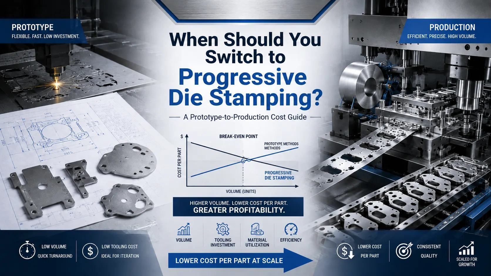
    CNC 가공과 금속 스탬핑 중 하나를 선택하는 것은 단순히 단가만 따져볼 문제가 아닙니다. 핵심은 부품의 형상, 설계 완성도, 예상 생산량, 그리고 제품 수명 주기 동안의 수요를 고려했을 때 전용 스탬핑 금형이 필요한지 여부입니다. CNC 가공은 시제품, 불확실한 수요, 솔리드 바 또는 블록 형태, 그리고 변경 가능성이 높은 부품에 더 안전한 선택인 경우가 많습니다. 금속 스탬핑은 안정적인 판금 설계가 오랫동안 반복적으로 사용되어 금형 투자 비용을 완제품 생산에 분산시킬 수 있을 때 더욱 매력적인 선택이 됩니다. 경우에 따라서는 기본 형상은 스탬핑으로 가공하고 핵심 형상만 가공하는 하이브리드 방식이 가장 위험 부담이 적은 해결책이 될 수 있습니다.

    CNC 가공, 금속 스탬핑, 아니면 하이브리드 공정?

    프로젝트 조건 CNC 가공 금속 스탬핑 하이브리드 경로
    디자인 변경 가능성 있음 튼튼한 적합성 공구 관련 위험도가 높음 부분적인 디자인 확정 후 가능
    수요 불확실성 튼튼한 적합성 정당화하기 어렵다 교량 생산에 유용합니다
    안정적인 반복 볼륨 수명주기 비용을 검토하세요. 유능한 후보자 유능한 후보자
    솔리드 바 또는 블록 형상 튼튼한 적합성 일반적으로 부적합함 제한된
    판재 또는 코일 형상 가능한 유능한 후보자 유능한 후보자
    정밀 구멍, 나사산 또는 기준면 튼튼한 적합성 추가 업무가 필요할 수 있습니다. 종종 실용적입니다

    생산량이나 디자인이 불확실할 경우 CNC 가공을 계속 진행하십시오.

    CNC 가공은 일반적으로 프로젝트의 기능, 적합성, 요구 사항 또는 최종 형상을 검증하는 단계에 적합합니다. 전용 생산 금형 없이도 수정 작업을 수용할 수 있으며, 판재, 봉재 또는 블록 소재로 복잡한 형상을 제작할 수 있습니다. 이러한 특징 덕분에 CNC 가공은 다음과 같은 장점을 제공합니다. 정밀 CNC 가공 서비스 이는 시제품, 시험 생산, 교체 부품 및 아직 금형 상각을 감당할 수 있는 물량이 부족한 반복 주문에 적합합니다.

    프로그래밍, 지그, 재료 수율, 배치 가격, 검사 및 수정 비용을 확인하십시오. 모든 부품에 긴 사이클 시간이 필요하거나 원재료를 많이 제거해야 하는 경우 가공 비용이 높아질 수 있습니다. 그러나 생산량과 관계없이 판재에서 형상을 만들 수 없는 경우에는 비용이 정확하게 유지될 수 있습니다.

    형상, 수요 및 디자인이 안정적일 때 스탬핑 금형에 투자하십시오.

    생산용 금형은 부품을 평판 소재에서 블랭킹, 피어싱, 벤딩, 포밍 또는 드로잉 가공할 수 있고, 부품의 변형 가능성이 낮을 때 실용적입니다. 금형 제작에는 초기 비용이 발생하지만, 반복 생산을 통해 투자 비용을 프로그램 전체에 분산시킬 수 있습니다. 재료의 특성, 공차 및 예상 마모는 사업 타당성에 영향을 미칩니다. 설계 변경이 발생할 경우 금형을 상당 부분 재작업해야 할 수 있으므로, 기능 테스트 및 도면 승인을 받은 후에 금형을 출시해야 합니다.

    승인하기 전에 정밀 금속 스탬핑 및 툴링 서비스재질, 두께, 성형 가능성, 주요 치수, 2차 가공, 수명 주기 및 개정 현황을 포함하는 제조 가능성 검토를 요청하십시오. 보편적인 생산 기준치는 스탬핑이 경제적이라는 것을 증명하지 못합니다.

    핵심 부위만 가공해야 하는 경우 하이브리드 공정을 사용하십시오.

    이러한 공정들이 항상 상충되는 선택지는 아닙니다. 스탬핑으로 제작된 블랭크는 외형, 굽힘, 성형된 형상을 만들어낼 수 있으며, 탭핑, 리밍, 연삭 또는 밀링은 중요한 접합면을 완성하는 데 사용될 수 있습니다.

    이 공정은 스탬핑된 부품이 반복 가능한 위치 기준점을 제공하고 2차 가공 사이클이 짧을 때 가장 효과적입니다. 성형 변형으로 인해 고정 장치가 불안정하거나 대부분의 형상에 여전히 가공이 필요한 경우에는 이 공정이 덜 적합합니다. 2차 가공을 거친 스탬핑 PCB 터미널 블록 이는 해당 원리를 입증합니다. 공개된 제조 공정은 정밀 스탬핑, 벤딩, 탭핑, 드릴링 및 전기 도금을 결합합니다.


    PCB 단자대는 정밀 스탬핑, 벤딩, 탭핑, 드릴링 및 2차 가공 공정을 통해 제조됩니다.

    스탬핑 툴링이 항상 수익성이 좋은 것은 아닌 이유

    평생 수요, 변화 및 숨겨진 운영을 고려하십시오.

    제품 수명 주기가 짧거나, 고객의 요구 사항이 자주 변경되거나, 수요가 불확실한 경우 금형 투자 비용을 회수할 만큼 충분한 부품이 소비되지 않을 수 있습니다. 낙관적인 연간 예측 하나에 의존하기보다는 수명 주기 동안의 생산량 중 낮은 수치, 예상 수치, 그리고 높은 수치를 모두 고려하여 모델링하십시오.

    스탬핑 부품의 최종 비용에는 디버링, 탭핑, 가공, 세척, 도금, 코팅, 검사, 조립, 포장, 금형 유지 보수 및 필요한 수정 비용이 모두 포함되어야 합니다. 견적서에는 시제품 검사, 샘플 검사, 수정 작업, 연마, 예비 부품, 보관 및 유지 보수가 포함되는지 여부를 명시해야 합니다. 금형 제작 시작 후 변경 사항은 비용 증가 및 지연을 초래할 수 있으므로 공식적인 금형 출시는 필수적인 관리 절차입니다.

    스탬핑 툴링 손익분기점 계산 방법

    완전히 정의된 두 가지 제조 경로를 비교하십시오.

    손익분기점 생산량 = 금형 투자액 ÷ (완성된 CNC 가공 단가 − 완성된 스탬핑 가공 단가)

    "완료된" 비용이 중요합니다. CNC 비용에는 재료비, 설치비, 가공비, 공구비, 검사비, 마감비, 포장비가 포함되어야 합니다. 스탬핑 비용에는 금형 설계, 시험 제작, 프레스 생산, 재료 사용료, 유지보수비, 2차 가공, 검사비, 마감비, 포장비가 포함되어야 합니다.

    스탬핑된 블랭크에 CNC 가공으로 구멍을 뚫고 나사산을 내야 하는 경우, 프레스 가공 가격만 사용하는 것이 아니라 완성된 하이브리드 부품의 원가를 기준으로 하십시오. 여러 생산량 시나리오를 검토해 보세요. 단가 차이가 작으면 투자 회수 기간이 길어지지만, 차이가 크면 금형 제작을 더 빨리 정당화할 수 있습니다.

    모든 입찰자에게 동일한 도면 수정, 재료, 수량 범위, 검사 범위, 마감, 포장 및 금형 소유권 조건을 제시하도록 요청하십시오. 그렇지 않으면 견적 내용이 서로 다를 수 있습니다. "스탬핑 금형 제작이 타당한 생산량은 얼마인가?"라는 질문에 대한 정답은 업계 전체의 수치가 아니라 프로젝트별 손익분기점 범위입니다.

    CNC 가공 부품은 금속 스탬핑에 적합한가요?

    먼저 해당 형상을 판재 또는 코일로 제작할 수 있는지 여부를 판단하십시오. 스탬핑은 평판 재료를 절단하고 성형하는 반면, 기계 가공은 솔리드 공작물에서 재료를 제거합니다. 두꺼운 부분, 밀폐된 형상 또는 복잡한 다중 평면 형상은 직접 변환이 불가능할 수 있습니다.

    스탬핑 가능한 부분과 중요한 가공 부분을 분리하십시오.

    먼저 기본 형태를 살펴보세요. 일정한 판재 두께를 사용할 수 있을까요? 굽힘, 드로잉 깊이, 구멍과 모서리 사이의 관계, 스프링백, 버(burr)에 민감한 표면 등을 검토하세요.

    도면의 형상을 스탬핑에 적합한 형상, 설계 또는 공차 변경 후 가공 가능한 형상, 그리고 여전히 기계 가공이 필요한 형상의 세 그룹으로 분류합니다. 정밀 보어, 깊은 나사산, 밀봉면, 베어링 위치 및 기준면은 2차 가공으로 남겨둘 수 있습니다. 위치 기준선, 가공 여유, 그리고 성형 편차가 최종 설정에 미치는 영향을 확인합니다. 2차 CNC 가공은 일반적으로 스탬핑 부품의 고정밀 보어 및 장착면에 사용됩니다.

    CNC 프로토타입에서 스탬핑 생산으로 전환하는 방법

    CNC 프로토타입은 기능을 검증하지만, 스탬핑 가능성을 반드시 보장하는 것은 아닙니다. 프로토타입 도면에는 날카로운 모서리, 가변적인 두께, 또는 성형이 아닌 가공을 중심으로 생성된 엄격한 공차 등이 포함될 수 있습니다.

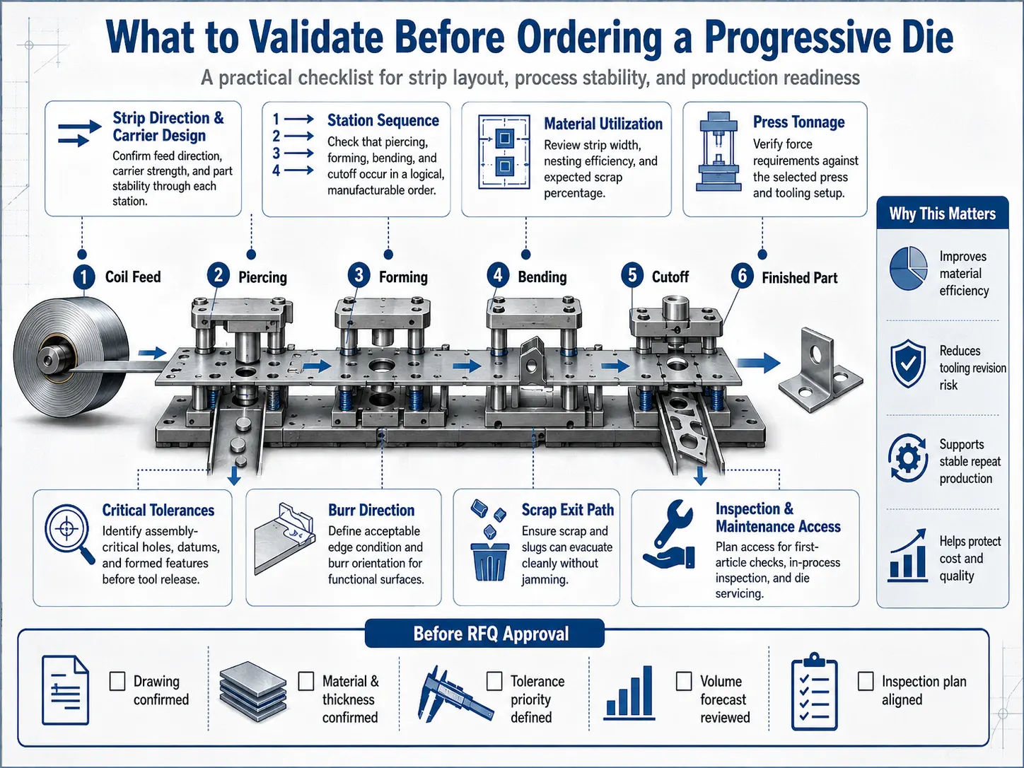
    요구사항을 동결한 후, DFM 및 초도품 승인을 활용하십시오.

    실제 금형 제작 전에 재질, 두께, 접합부, 주요 치수, 마감 처리 및 도면 개정 사항을 확인하십시오. 기능 또는 고객 인터페이스 변경이 진행 중인 프로젝트는 주요 위험 요소가 해결될 때까지 유연한 프로세스를 유지해야 합니다.

    통제된 전환은 다음 순서를 따릅니다: 시제품 검증, 스탬핑 DFM(설계 제조성 검토), 생산 도면 수정, 금형 설계, 금형 시험, 샘플 검사, 수정, 초도품 승인, 시범 생산 및 양산 출시. 샘플 검토에는 치수뿐 아니라 버, 균열, 주름, 스프링백, 도금 상태, 외관 및 조립 성능도 포함되어야 합니다.

    CNC 가공에서 스탬핑 가공으로의 전환을 위한 견적 요청서(RFQ)에 구매자가 포함해야 할 사항

    정확한 견적을 위해서는 최신 2D 도면 및 STEP 파일, 재료 및 재고 현황, 두께, 연간 및 수명 주기별 생산량, 현재 공정, 중요 공차, 마감 처리, 2차 가공, 검사, 포장, 그리고 알려진 변경 사항이 필요합니다.

    또한 공구 소유권, 보관, 유지 보수, 연마, 예비 인서트, 수정 비용, 양도 권한 및 프로그램 종료 처리 비용도 비교하십시오. 금형 가격이 낮으면 엔지니어링 변경이나 생산 지원이 제외될 경우 나중에 비용이 증가할 수 있습니다.

    CNC 가공에서 스탬핑 가공으로의 전환을 위한 공급업체 선정

    자격을 갖춘 공급업체는 두 가지 방식을 모두 평가해야 합니다. 금형이 자체 제작되는지, 시험 및 생산 팀이 책임을 공유하는지, 2차 작업이 조정 가능한지, 그리고 초도품, 수정 사항, 금형 마모 및 시정 조치가 어떻게 관리되는지 확인해야 합니다.

    CK 메탈 테크(CK Metal Tech)로도 알려진 저장 추앙카이 기계전기기술 유한회사는 공구 제작, 금속 스탬핑, CNC 가공, 표면 처리, 검사 및 조립을 자사 내에 통합하여 제공합니다. 통합 정밀 금속 제조 CK Metal Tech는 8대의 4축 CNC 머신, 18대의 정밀 CNC 선반, 그리고 스위스식 가공 설비를 보유하고 있습니다. 또한, 프로그레시브, 드로잉, 컴파운드 툴링을 생산하며 IATF 16949 인증을 획득하여 완전 CNC, 완전 스탬핑, 하이브리드 공정 검토를 지원합니다.

    결론

    스탬핑 툴링은 부품이 실제로 스탬핑에 적합하고, 설계가 안정적이며, 툴링, 유지보수, 검증, 2차 가공 및 수정 위험을 고려했을 때 총비용 절감 효과가 클 경우에 경제적입니다. CNC 가공은 시제품 제작, 설계 변경, 솔리드 형상 및 정밀 형상 가공에 여전히 유용합니다. 기본 형상은 스탬핑이 가능하지만 기능적 인터페이스에는 여전히 가공이 필요한 경우, 하이브리드 공정이 가장 균형 잡힌 선택일 수 있습니다.

    프로젝트 검토를 위해 최신 도면, STEP 파일, 자재, 목표 수량, 프로그램 기간, 중요 치수, 2차 가공 작업 및 품질 요구 사항을 준비해 주십시오. 이러한 세부 정보를 통해 CK Metal Tech는 다음과 같은 작업을 수행할 수 있습니다. CNC 가공에서 스탬핑 가공으로의 DFM 검토를 요청합니다. 즉각적인 장비 도입 없이 실행 가능한 경로를 비교할 수 있습니다.

    자주 묻는 질문

    생산량이 어느 정도일 때 금속 스탬핑이 CNC 가공보다 저렴해질까요?

    보편적인 기준치는 없습니다. 손익분기점은 실제 공구 투자액과 CNC 가공 및 스탬핑 가공 완료 비용의 차액을 기준으로 계산하며, 여기에는 유지보수, 2차 가공, 후가공, 검사 및 설계 변경 위험이 포함됩니다.

    CNC 가공 부품을 금속 스탬핑 부품으로 직접 변환할 수 있습니까?

    경우에 따라 다르지만, 일반적으로 DFM(설계 제조성 검토) 없이는 불가능합니다. 솔리드 섹션, 가변 두께, 깊은 형상 또는 엄격한 공차를 가진 경우, 툴링 시작 전에 재설계가 필요할 수 있습니다.

    스탬핑 부품에도 CNC 가공이 여전히 필요한가요?

    그럴 수도 있습니다. 나사산, 정밀 구멍, 베어링 끼워맞춤, 밀봉면, 기준면 또는 꽉 조이는 장착부에는 2차 가공, 드릴링, 탭핑, 리밍 또는 연삭이 필요할 수 있습니다.

    구매자는 스탬핑 툴링이 수익성이 있을지 어떻게 알 수 있을까요?

    특허 출원 가능성을 확인한 후, 낮은 수요, 예상 수요, 높은 수요 시나리오에서 전체 수명 주기 비용을 비교하십시오. 설계가 확정되고 숨겨진 작업이 두 견적 모두에 포함된 경우, 타당성이 더욱 높아집니다.

    스탬핑 금형 제조업체를 선택할 때 무엇을 확인해야 할까요?

    사내 공구 설계, DFM 지원, 시험, 초도품 절차, 개정 관리, 2차 가공, 검사, 공구 유지 보수, 소유권 조건 및 생산 품질 관리를 점검하십시오.

    왓츠앱
    이메일
    콘택트 렌즈